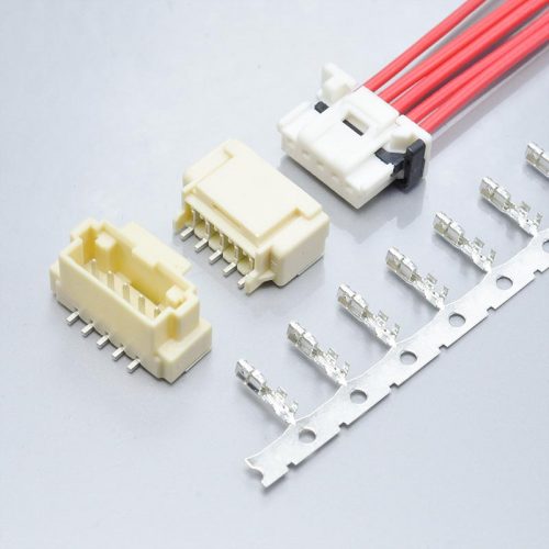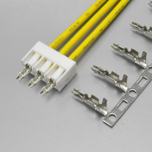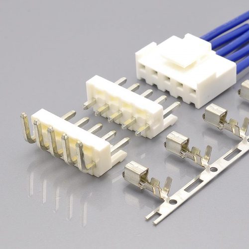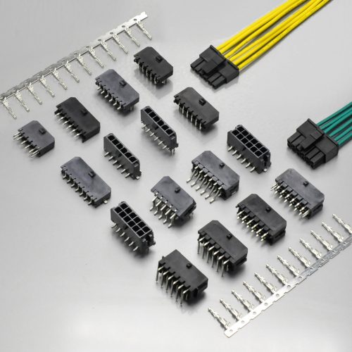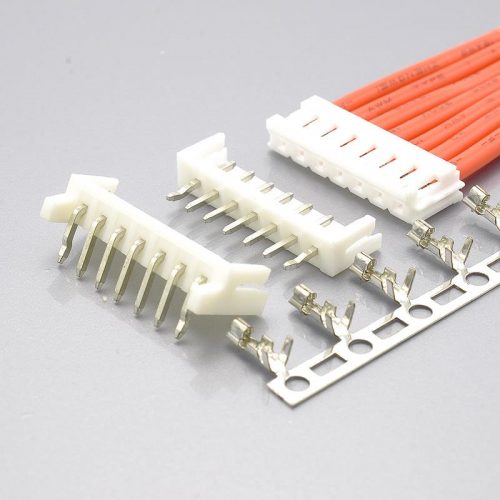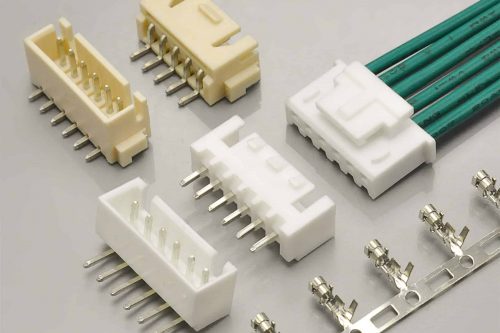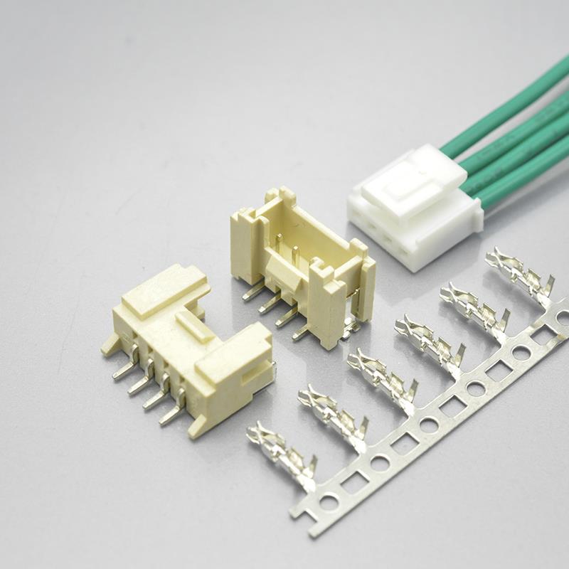
Quick answer: The YEONHO YH200 is a 2.00mm pitch, single-row, wire-to-board crimp connector with a lock — the locked counterpart to the plain friction-retention PH-style connector in the same pitch. The KONNRA KR2004 is the cross-reference equivalent, and it is a fully documented one on the KONNRA side: a seven-page product specification and a set of six engineering drawings covering the housing, the terminal and all four wafer styles. It is rated 250V AC/DC, 2A AC/DC at AWG #22, over −40°C to +105°C, with 1,000MΩ minimum insulation resistance, 20mΩ maximum contact resistance and a 1,000V AC dielectric strength — and it carries a lock, which is the whole reason this part exists separately from the plain PH connector next to it in the same catalogue.
This guide comes with one limitation stated up front, because it affects how you should use everything below.
We could not obtain YEONHO’s own documentation for this series. YEONHO is a Korean manufacturer; its public site returned no machine-readable content during this review, and no YEONHO datasheet for the series named by the cross-reference could be located. What can be found for “YEONHO 2.0mm” is a set of third-party listings — clone manufacturers and distributors — and they disagree with each other: the same family is variously published as 5A, 3A and 2A, at wire ranges from AWG #24–28 to AWG #22–30, and the series itself is referred to under at least four different names. That disagreement is documented in detail in the “What we could not verify” section below, and it is the single most important practical finding on this page.
So: for this particular cross-reference, the paper comparison cannot be closed. The KONNRA side is unusually well documented; the YEONHO side is not available to us. That means the validation has to be done against your drawing or your existing part, and we will do it in writing — which is what the contact section at the end is for.
Every figure attributed to KONNRA below is traceable to a source listed in the final section. Where a number could not be verified against the original, that is stated rather than filled in.
At a glance
| Parameter | KONNRA KR2004 | Verified against the original? |
|---|---|---|
| Pitch | 2.00mm | Series-level match |
| Configuration | Single row, wire-to-board, crimp | Series-level match |
| Retention | Lock (buckle) | Series-level match — this is the defining feature of the cross-referenced family |
| Rated voltage | 250V AC/DC | Not verified — original documentation unavailable |
| Rated current | 2A AC/DC at AWG #22 | Not verified — third-party sources claim 3A and 5A for related families |
| Temperature range | −40°C to +105°C | Not verified |
| Insulation resistance | 1,000MΩ min | Not verified |
| Contact resistance | 20mΩ max | Not verified |
| Dielectric strength | 1,000V AC / 1 minute | Not verified |
| Applicable wire | AWG #22 to #28 (PS and drawing) | Not verified |
| Insulation O.D. | 1.2mm to 1.6mm | Not verified |
| Circuits | 2 to 16 | — |
| Wafers offered | DIP 90° and 180°, SMT 90° and 180° | — |
| Durability | 30 cycles, 40mΩ max after | — |
| Temperature rise | 30°C max | — |
| Mating force table | Published, 2–16 circuits | Not verified — and see the note on the lock below |
| UL / CSA | not published on the specification | — |
| Documentation available | 7-page PS + 5 engineering drawings | Original: not located |
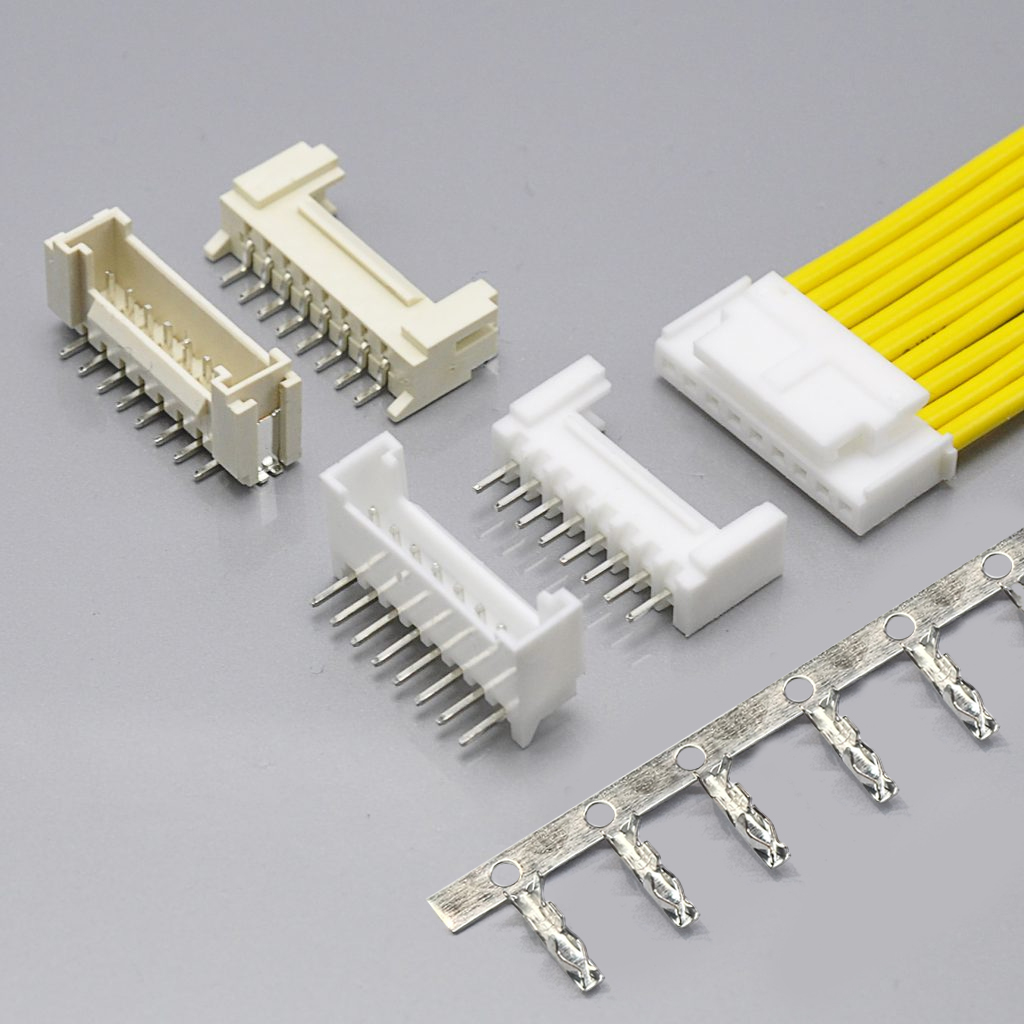
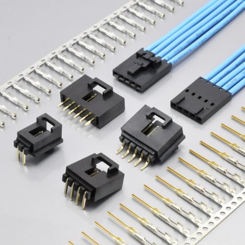
KR2004 — KONNRA’s locked 2.0mm PH-style equivalent
Two rows in that table are worth expanding before anything else: the lock, which is what makes this a different connector from the plain PH part beside it, and the AWG #22 qualification, which is the most distinctive number on the KONNRA specification.
What “with lock” actually changes
The 2.00mm pitch class contains two adjacent products in KONNRA’s own catalogue that share a name, a pitch, a circuit range, a current rating and a voltage rating — and differ on exactly one feature:
| KR2001 | KR2004 | |
|---|---|---|
| Cross-references | JST PH 2.0 | YEONHO YH200 PH 2.0 |
| Pitch | 2.00mm | 2.00mm |
| Current | 2A at AWG #24 | 2A at AWG #22 |
| Voltage | 100V | 250V |
| Circuits | 2–16 | 2–16 |
| Retention | Friction — no lock | Lock (buckle) |
| Dielectric strength | 800V AC | 1,000V AC |
| Wire range | AWG #24–28 | AWG #22–28 |
The lock is the reason both exist. A friction-retention connector relies on the housing’s grip on the header shroud, and on the terminal’s grip in the housing. That is adequate for a great many applications and it is what the plain PH connector has been doing for decades. But it has two known failure modes in the field:
- Vibration. A friction fit has no positive engagement, so a vibrating environment can work the mated pair apart over time.
- Handling. A harness that gets pulled during assembly, packing or service will separate at a friction joint in a way that a latched joint resists.
A lock addresses both, and the cost is an additional assembly step: the operator has to seat the latch, and later release it to unmate. On high-volume assembly that is a real cost, which is exactly why the unlocked variant still exists alongside it.
And there is a force consequence you should know about before you specify a locked part. KONNRA’s KR2004 specification contains a durability clause at §6.1 that describes the insertion and withdrawal test as “excluding plastic detents” — that is, the mating force the connector’s lock contributes is deliberately excluded from the force measurements. So the published insertion force for this part is the force of the contact system, not the force an operator feels when they push the latch home. The real insertion force is higher, and by an amount the specification does not state.
That is worth knowing on any locked connector, not just this one. When you size a mating-force budget or an operator ergonomics limit on a latched part, check whether the published figure includes or excludes the latch. On this series it excludes it, and the specification says so.
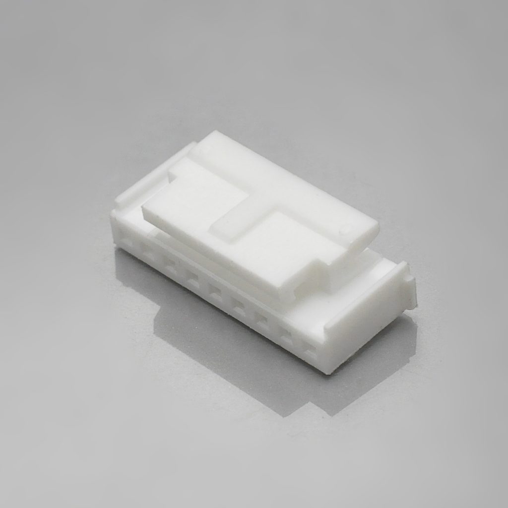
KR2004 housing with lock
The naming puzzle: one series, four names
This is the finding that most affects whether you can use the cross-reference at all, and it is worth laying out clearly because it is easy to walk into.
KONNRA names the original as “YEONHO YH200 PH 2.0”. Searching for the same family in the wider market produces at least four different series names, applied by different suppliers to what appear to be related 2.00mm locked connectors:
| Name seen | Where it appears | What it is described as |
|---|---|---|
| YH200 | KONNRA’s cross-reference page; clone listings | The series named by the cross-reference |
| YDH200 | Clone manufacturers’ listings | “YEONHO equivalent housing connector, 2.0mm wire-to-board” |
| SMH200 | Distributor listings | A 2.0mm housing, described alongside a YST200 terminal |
| YST200 | Distributor and clone listings | A terminal, described as “Compatible: YST200 Series” |
| SMAW200 / SMW200 | Clone manufacturers’ listings | A 2.0mm series, also described at 2*7 dual-row |
Some of this is explicable. A connector family legitimately splits its name across its parts — the housing, the terminal and the wafer can each carry a different designation, and a distributor will often index the part by whichever piece a customer searched for. YST200 being described as a terminal while SMH200 is described as a housing is consistent with that pattern.
Some of it is not. Whether YH200, YDH200 and SMH200 are the same family, three sub-families, or genuinely different connectors is not something we can resolve from the available sources — and it matters, because if they are different families they may carry different ratings, which is exactly what the next section shows.
What to do about it: identify your part by measurement and drawing, not by the series name. The identification section below gives the measurements that separate the families in this pitch. And if you have the original drawing, send it — that resolves the question in one step.
The ratings — and where the third-party sources disagree
The KR2004 specification publishes the following. All of it is from the controlled document, and all of it is internally consistent except where noted.
| Item | KONNRA KR2004 specification |
|---|---|
| Rated voltage | 250V AC/DC |
| Rated current | 2A AC/DC, qualified at AWG #22 |
| Ambient temperature range | −40°C to +105°C |
| Applicable wire | AWG #22 to #28; insulation O.D. 1.2mm to 1.6mm |
| Contact resistance | 20mΩ max — dry circuit at 20mV / 100mA between the A and B regions of the mated pair, to EIA-364-23C |
| Insulation resistance | 1,000MΩ min — 500V DC for one minute between adjacent contacts, to EIA-364-21B |
| Dielectric strength | 1,000V AC for one minute between adjacent terminals or terminal to ground, to EIA-364-20A, with the acceptance criterion “No Breakdown and Flashover” |
Note the wire qualification: 2A at AWG #22. This is the largest wire the part accepts, and it is the gauge at which the current rating applies. That is the correct way to publish a current rating — and it is a genuinely different figure from the neighbouring KR2001, whose 2A is qualified at AWG #24 with a wire range starting at #24 rather than #22. On the same pitch, in the same catalogue, one part accepts a heavier wire than the other, and it is this one.
And note the dielectric strength: 1,000V AC. That is higher than the 800V AC specified on the plain PH 2.0 connector, and it is consistent between the specification and the engineering drawings. For a 250V-rated part, a 1,000V proof voltage is a 4× margin.
Now the disagreement
No YEONHO datasheet was located. The figures published for this family by third-party sources — clone manufacturers and distributors — do not agree with each other, or with the cross-reference:
| Source type | Current rating published | Wire range published |
|---|---|---|
| Clone manufacturer listing for YH200 | 5A AC, DC | AWG #24–28 |
| Clone manufacturer listing for YDH200 | 3A AC, DC | not stated |
| Distributor listing for YST200 | up to 3A | AWG #22–30 |
| Clone manufacturer describing “YEONHO 2.0” | 3.0A AC/DC, 250V | not stated |
| KONNRA KR2004 specification | 2A AC/DC | AWG #22–28 |
Read that column carefully, because it spans a factor of 2.5. The same nominal family is published at 2A, 3A and 5A depending on who is writing, and the wire ranges run from #24–28 to #22–30.
Three explanations are possible, and we cannot distinguish between them from the available evidence:
- They are different sub-series. The naming puzzle above is real, and if
YH200,YDH200andSMH200are distinct families, they may genuinely carry different ratings. This is the most likely explanation for part of the spread. - Some figures are marketing rather than specification. A clone manufacturer quoting a headline current without a wire gauge or a temperature-rise condition is not publishing a rating in the same sense that a controlled specification is.
- The cross-reference understates the original. It is possible that the family named by KONNRA is rated above 2A, in which case the KR2004’s 2A is conservative.
We are not going to pick one. The point of stating all three is that you should not accept any of them without the drawing — including ours. If your requirement is 3A or 5A at this pitch, the question of what the original is actually rated at is the first thing to settle, and it is settled by a document rather than by a listing.
What we can say with confidence is that the KR2004’s 2A at AWG #22 is a conservative figure rather than an aggressive one. AWG #22 is a heavier conductor than AWG #24, and the part is qualified to carry 2A through it with a 30°C maximum temperature rise — a specified, tested limit rather than a nominal one. If your load is below 2A, the part is specified with margin. If your load is above 2A, or if you are replacing a part you believe to be rated higher, ask us and we will address it against your specific requirement rather than against a catalogue headline.
The force table: three exact laws, and a cross-over with the unlocked part
KONNRA publishes a complete insertion and withdrawal force table for the KR2004 across the full 2-to-16 circuit range, both as new and after the rated 30 cycles.
| Circuits | Insertion force (max) | Withdrawal force (min), initial | Withdrawal force (min), after 30 cycles |
|---|---|---|---|
| 2 | 1.20 | 0.40 | 0.25 |
| 3 | 1.80 | 0.60 | 0.40 |
| 4 | 2.40 | 0.80 | 0.55 |
| 5 | 3.00 | 1.00 | 0.70 |
| 6 | 3.60 | 1.20 | 0.85 |
| 7 | 4.20 | 1.40 | 1.00 |
| 8 | 4.80 | 1.60 | 1.15 |
| 9 | 5.40 | 1.80 | 1.30 |
| 10 | 6.00 | 2.00 | 1.45 |
| 11 | 6.60 | 2.20 | 1.60 |
| 12 | 7.20 | 2.40 | 1.75 |
| 13 | 7.80 | 2.60 | 1.90 |
| 14 | 8.40 | 2.80 | 2.05 |
| 15 | 9.00 | 3.00 | 2.20 |
| 16 | 9.60 | 3.20 | 2.35 |
(All values in kgf. 1 kgf = 9.8N.)
The three laws
Read the columns as sequences and the specification reduces to three exact statements, with no exceptions across the whole range:
Insertion force rises by exactly 0.60 kgf per circuit. In closed form, insertion force (max) = 0.60 × (circuits) — 1.20 at two positions, 9.60 at sixteen.
Initial withdrawal force rises by exactly 0.20 kgf per circuit: withdrawal force (min) = 0.20 × (circuits) — 0.40 at two positions, 3.20 at sixteen.
Post-30-cycle withdrawal force rises by exactly 0.15 kgf per circuit: 0.15 × (circuits) − 0.05 — 0.25 at two positions, 2.35 at sixteen.
Those three laws are worth carrying into a design review, because they let you sanity-check any quoted figure for this series. An insertion force that is not 0.60 kgf per circuit, or an initial withdrawal force that is not 0.20 kgf per circuit, does not fit the specification as published.
The retention loss grows with circuit count — the opposite of the last part
Now subtract the last column from the second:
| Circuits | Initial withdrawal | After 30 cycles | Lost | Lost, as a share |
|---|---|---|---|---|
| 2 | 0.40 kgf | 0.25 kgf | 0.15 kgf | 37.5% |
| 4 | 0.80 | 0.55 | 0.25 | 31.3% |
| 6 | 1.20 | 0.85 | 0.35 | 29.2% |
| 8 | 1.60 | 1.15 | 0.45 | 28.1% |
| 10 | 2.00 | 1.45 | 0.55 | 27.5% |
| 12 | 2.40 | 1.75 | 0.65 | 27.1% |
| 16 | 3.20 | 2.35 | 0.85 kgf | 26.6% |
The absolute retention loss grows with circuit count — from 0.15 kgf on a 2-position connector to 0.85 kgf on a 16-position one. The relative loss falls gently, from 37.5% to 26.6%, but it never becomes small.
This is a different pattern from other series we have documented in this catalogue, and the difference is worth knowing if you work across several of them. On a plain PH 2.0 connector we documented a fixed loss of 0.20 kgf at every position count, which made the relative loss collapse from 40% at two positions to 10.5% at sixteen. On this locked part the loss scales with the connector, so a 16-position KR2004 loses 0.85 kgf where a 16-position plain PH connector loses 0.20 kgf. The series that holds harder as new also loses more as it ages, and the two facts come from the same document.
A design consequence worth stating. At 2 positions the KR2004’s retention at cycle 30 is 0.25 kgf — about 2.45N. That is a specified minimum and the part is qualified to it, but it is not much, and the loss over the rated life is 37.5% of the beginning-of-life figure. For a 2-position locked connector in a vibrating application, specify against the 30th-cycle column, not the initial one. Note also that the specification’s own force table excludes the lock’s contribution (see §6.1, discussed above) — so the lock is additional retention on top of these figures, which is precisely what you are buying the locked variant for.
The cross-over: the locked part is easier below 15 circuits
Here is the most useful comparison on this page, and it is only visible because both products sit in the same catalogue at the same pitch.
KONNRA’s plain PH 2.0 part (the KR2001) publishes insertion force = 1.5 + 0.50 × (circuits) and initial withdrawal force = 0.30 + 0.10 × (circuits). The locked part above publishes 0.60 × (circuits) and 0.20 × (circuits). Set them side by side:
| Circuits | KR2001 insertion (unlocked) | KR2004 insertion (locked) | KR2001 withdrawal | KR2004 withdrawal |
|---|---|---|---|---|
| 2 | 2.50 | 1.20 | 0.50 | 0.40 |
| 4 | 3.50 | 2.40 | 0.70 | 0.80 |
| 6 | 4.50 | 3.60 | 0.90 | 1.20 |
| 8 | 5.50 | 4.80 | 1.10 | 1.60 |
| 10 | 6.50 | 6.00 | 1.30 | 2.00 |
| 12 | 7.50 | 7.20 | 1.50 | 2.40 |
| 14 | 8.50 | 8.40 | 1.70 | 2.80 |
| 15 | 9.00 | 9.00 | 1.80 | 3.00 |
| 16 | 9.50 | 9.60 | 1.90 | 3.20 |
Two clean results fall out of that table.
The insertion forces converge and cross at exactly 15 circuits. Below 15, the locked part needs less insertion force than the unlocked one — dramatically so at low position counts, where a 2-position locked connector needs 1.20 kgf against 2.50 kgf for the unlocked one, less than half. Above 15, the locked part needs very slightly more. The two laws are 1.5 + 0.5n and 0.6n, and they intersect precisely at n = 15.
The withdrawal forces cross at exactly 3 circuits. 0.30 + 0.10n and 0.20n are equal at n = 3, where both give 0.60 kgf. From 4 circuits upward, the locked part holds harder — and by 16 circuits it holds 3.20 kgf against 1.90 kgf, about 68% more.
What that means in practice. If you are choosing between the two on force grounds alone:
- On a small connector, the locked variant is easier to mate, not harder. A 2-position locked KR2004 needs less than half the insertion force of the 2-position unlocked KR2001 — and it holds 0.40 kgf against 0.50 as new, but that comparison ignores the lock, which the force table excludes. The lock is extra retention on top.
- On a large connector, the locked variant is harder to mate and holds considerably harder. At 16 positions it needs 9.60 kgf to insert against 9.50, and holds 3.20 kgf against 1.90.
- And on any of them, the published insertion force is the contact system only. Add the latch force before you size an assembly operation.
One caution about that cross-over. These are two different connector systems with different terminals, different housings and different wafer designs. The fact that their force curves cross at a particular position count is a published-data observation, not an invitation to substitute one for the other on force grounds. What it does tell you is that “locked means harder to mate” is not a safe assumption — on this pitch, at low position counts, it is false.
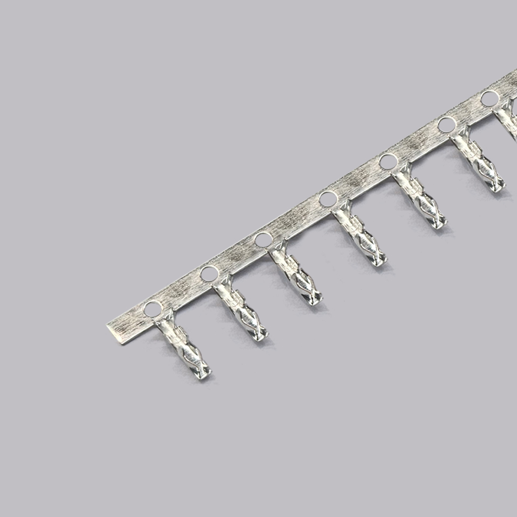
KR2004 terminal
Crimp, and the AWG #22 window
The KR2004’s crimp specification covers four wire gauges rather than three, because it starts one gauge larger than the plain PH part:
| Crimp parameter | 22 AWG | 24 AWG | 26 AWG | 28 AWG |
|---|---|---|---|---|
| Conductor crimp width (①) | 1.30 ± 0.10 | 1.30 ± 0.10 | 1.30 ± 0.10 | 1.30 ± 0.10 |
| Conductor crimp height (①) | 0.85 ± 0.05 | 0.80 ± 0.05 | 0.75 ± 0.05 | 0.70 ± 0.05 |
| Insulation crimp width (②) | 1.60 Max | 1.60 Max | 1.60 Max | 1.60 Max |
| Insulation crimp height (②) | 1.70 ± 0.05 | 1.55 ± 0.05 | 1.40 ± 0.05 | 1.30 ± 0.05 |
| Crimp strength | 4.54 kgf min | 3.63 kgf min | 2.27 kgf min | 1.36 kgf min |
| Stripping length | 1.5–2.1mm | 1.5–2.1mm | 1.5–2.1mm | 1.5–2.1mm |
| Terminal quantity | 12,000 pcs per reel |
Four things worth reading out of that table.
The conductor crimp height steps by exactly 0.05mm per gauge — 0.85, 0.80, 0.75, 0.70 — inside a ±0.05mm window at every gauge. A 0.10mm wide window on a sub-millimetre target is a tight process, and it is why the applicator setup is worth verifying by measurement rather than by eye.
The AWG #22 crimp strength is 4.54 kgf minimum — the highest crimp pull-out figure we have documented on any 2.00mm series in this catalogue, and higher than the same manufacturer specifies at AWG #24 on the plain PH part (3.63 kgf). A heavier conductor crimped in a correspondingly larger barrel simply pulls harder, and the specification reflects it.
The insulation crimp width is published as a maximum (1.60 Max), not a tolerance band. That is a different convention from the conductor crimp width (1.30 ± 0.10) in the same table. Read it as a ceiling: the insulation barrel must not close beyond 1.60mm.
The stripping length is a single figure for all four gauges (1.5–2.1mm). Note that this differs from other series in this catalogue — the plain PH part specifies 1.5–2.0mm, and one 2.00mm board-in series we documented specifies different stripping lengths for its 90° and 180° terminals (2.4–2.8mm and 1.5–2.0mm). Here, one strip length covers the whole range, which is a genuine process simplification — and it is worth confirming against the tooling documentation rather than assuming it transfers between series.
A note on the terminal itself. The terminal drawing specifies phosphor bronze, tin-plated over nickel, applicable wire AWG #28–#22, insulation O.D. 1.2 to 1.6mm, at 12,000 pieces per reel. The wire range stated on the drawing matches the product specification’s §4.0 — which is not the case on every series in this catalogue, as the next section shows.
The wire range, and where the product page drops the important part
The KR2004’s wire range is stated in three places in KONNRA’s documentation, and they do not all say the same thing.
| Source | Wire range stated |
|---|---|
| Product specification PS-KR2004-01 §4.0 | AWG 22# ~ 28#, insulation O.D. 1.2 to 1.6mm |
Terminal drawing (2004TF101-A-S) |
AWG #28 ~ #22, insulation O.D. 1.2 to 1.6mm |
| Product page — General Specifaction table | insulation O.D. 1.2 to 1.6mm (no wire range) |
| Product page — Overview prose | “AWG #24-#28” |
The specification and the drawing agree. The product page’s Overview paragraph says AWG #24–#28, which drops AWG #22 entirely.
That is the more consequential of the two errors we found on this product page, because AWG #22 is the gauge the current rating is qualified at. The specification’s headline rating is “Rated Current (Max.) 2A(22AWG)” — 2 amperes through an AWG #22 conductor. A reader who takes the wire range from the Overview paragraph will conclude that the connector accepts AWG #24–#28, that the correct wire for a 2A load is therefore AWG #24, and that AWG #22 is not an option. All three conclusions are wrong, and the third one removes the configuration the rating was written for.
Cite the specification. The wire range is AWG #22 to #28 with insulation 1.2mm to 1.6mm, and the current rating is qualified at AWG #22.
And note what the wire range means relative to the neighbouring part. The plain PH 2.0 connector next to it in the same catalogue covers AWG #24–28; this locked part covers AWG #22–28. The locked variant therefore reaches one gauge heavier, which is consistent with its 2A rating being qualified at #22 rather than #24 — and with its 4.54 kgf crimp strength at that gauge. If your harness uses AWG #22, this is the part in the pair that accepts it.
The insulation window
1.2mm to 1.6mm on both the specification and the terminal drawing — a window rather than a ceiling, which is the more useful way to publish it. It is a narrower and higher window than several other 2.00mm series in this catalogue (where the limits run to 1.4mm or 1.5mm), and it follows from the larger wire: an AWG #22 conductor with 1.2mm or more of insulation.
A wire below 1.2mm insulation has no published equivalent on this part, and a wire above 1.6mm is outside it. Measure the insulation rather than reading it off a catalogue page — the insulation crimp height is set against that diameter, and on this part the insulation crimp height window is only ±0.05mm.
What the engineering drawings add — and three things they get wrong or leave ambiguous
The KR2004 series drawing file contains six drawings: the housing, the terminal, and four wafers (DIP 90°, DIP 180°, SMT 90°, SMT 180°). Read together they contain a set of design facts the specification does not carry, and three points where a careful reader can go wrong.
The dimensions
Housing (2004H101-A-S, Rev A4), A and B advancing by 2.00mm per circuit:
| Circuits | A | B | C |
|---|---|---|---|
| 2 | 2.00 | 4.60 | 5.60 |
| 10 | 18.00 | 20.60 | 21.60 |
| 16 | 30.00 | 32.60 | 33.60 |
DIP 90° wafer (2004WRD101-A-S, Rev A04): A 2.00 → 30.00, B 6.00 → 34.00, C 4.90 → 32.90.
DIP 180° wafer (2004WVD101-A-S, Rev A05): the same numbers, but the table labels them the other way round — its “A” column carries 6.00 at two positions and 34.00 at sixteen, which is the DIP 90° table’s B column.
This is a labelling difference, not a dimensional one, and the two wafers are the same size in the same axis. But if you are comparing a 90° footprint against a 180° footprint by reading the A and B columns across the two tables, you will conclude they differ by 4.00mm when they do not. Check which dimension each table is calling A before you compare them.
SMT wafers carry four dimensions (A, B, C, D), because the SMT body extends further and includes a solder-tab position: SMT 180° runs A 8.00 → 36.00, B 2.00 → 30.00, C 2.70 → 15.50, D 4.90 → 32.90.
Both DIP drawings carry a recommended PCB layout with a total tolerance of ±0.05mm.
The DIP wafers have no solder tabs; the SMT wafers do
The material blocks make this explicit:
- SMT wafer: insulator LCP UL94 V-0, contact brass, solder tab phosphor bronze, all tin-plated over nickel.
- DIP wafer: insulator PA66 UL94 V-2, contact brass, solder tab: None.
So on the SMT version the connector is held to the board by brass contacts plus phosphor-bronze solder tabs; on the DIP version there are no tabs at all — retention is the through-hole solder joints alone. If your design or your qualification assumption relies on a solder nail, that exists on the SMT wafer and not on the DIP one, and nothing in the electrical specification will catch the difference.
Point one: the flammability grade depends on the colour
The specification states the housing material as “PA66 UL94 V-0 or 2”. The housing drawing states “PA66 UL94 V-2”. And the housing ordering code resolves the difference:
| Insulator code | Material | Flammability |
|---|---|---|
| 03 | PA66 White | V-2 |
| 21 | PA66 Blue | V-0 |
| 46 | PA66 Yellow | V-0 |
So the specification’s “V-0 or 2” is accurate and the drawing’s plain “V-2” is the white variant only. The two documents are not in conflict; the drawing simply describes the default colour.
The design consequence is worth stating plainly: if your specification requires UL94 V-0, you must order blue or yellow — the natural white housing is V-2. That is the kind of requirement that gets written into a qualification file as “housing: UL94 V-0” and then quietly fails on a white part.
The same pattern runs through the wafers, and there the picture is less favourable for through-hole. The SMT wafers use LCP insulator, UL94 V-0, in all cases. The DIP wafers use PA66 UL94 V-2:
| Wafer | Insulator colours and grades |
|---|---|
| SMT 90° and SMT 180° | LCP, UL94 V-0 (natural) |
| DIP 90° | 03 PA66 White V-2 · 22 PA66 Beige V-0 |
| DIP 180° | 03 White V-2 · 04 Black V-2 · 32 Red V-2 · 45 Yellow V-2 |
So a V-0 requirement is satisfied by any SMT wafer, or by the DIP 90° wafer in beige — but not by the DIP 180° wafer in any published colour. If your board is through-hole and your specification says V-0, that is a real constraint on this series and worth confirming before you commit. Ask us, and we will tell you what is available on the specific part number rather than leaving you to infer it from an ordering code.
Point two: a dimension in the SMT 90° table is wrong
The SMT 90° wafer table’s A column runs 8.00, 10.00, 12.00 … 34.00 in clean 2.00mm steps from two circuits to fifteen — a rule of A = 4.00 + 2.00 × (circuits). At sixteen circuits it reads:
16.80
The rule demands 36.00, and the SMT 180° wafer table — which is otherwise dimensionally identical in this column — publishes 36.00 for the same sixteen-circuit part. So the SMT 90° table’s sixteen-position A value is a transcription error, and the correct figure is 36.00.
We are flagging this as an observation on the published drawing rather than correcting it unilaterally, because the drawing is the controlled document and we are not its author. If you are laying out a sixteen-position SMT right-angle footprint from that table, take the 36.00 from the SMT 180° table or ask us — a 16.80mm body on a 16-position 2.00mm pitch part is not physically coherent, since the pitch alone consumes 30.00mm across fifteen gaps.
Point three: the housing part number is written two different ways
The specification’s part-number table gives the housing as H2004M101A. The housing drawing’s ordering code gives it as undefined + insulator + undefined — for example H2004M***0301A, where the first three wildcards are the circuit code (102 for 2, 116 for 16) and undefined is the insulator code.
The two forms are structurally different: the specification’s version carries a literal 1 after the M and four wildcards, while the drawing’s version carries three wildcards followed by a two-digit insulator code. Only the drawing’s form lets you specify the colour and therefore the flammability grade.
Order from the drawing’s form. If you order from the specification’s shorthand you cannot express the insulator code — and on this part the insulator code is what determines whether you get V-0 or V-2. Confirm the exact orderable string with us for your circuit count and colour; it is the kind of detail where a transposed digit produces a part that fits and fails a flammability requirement.
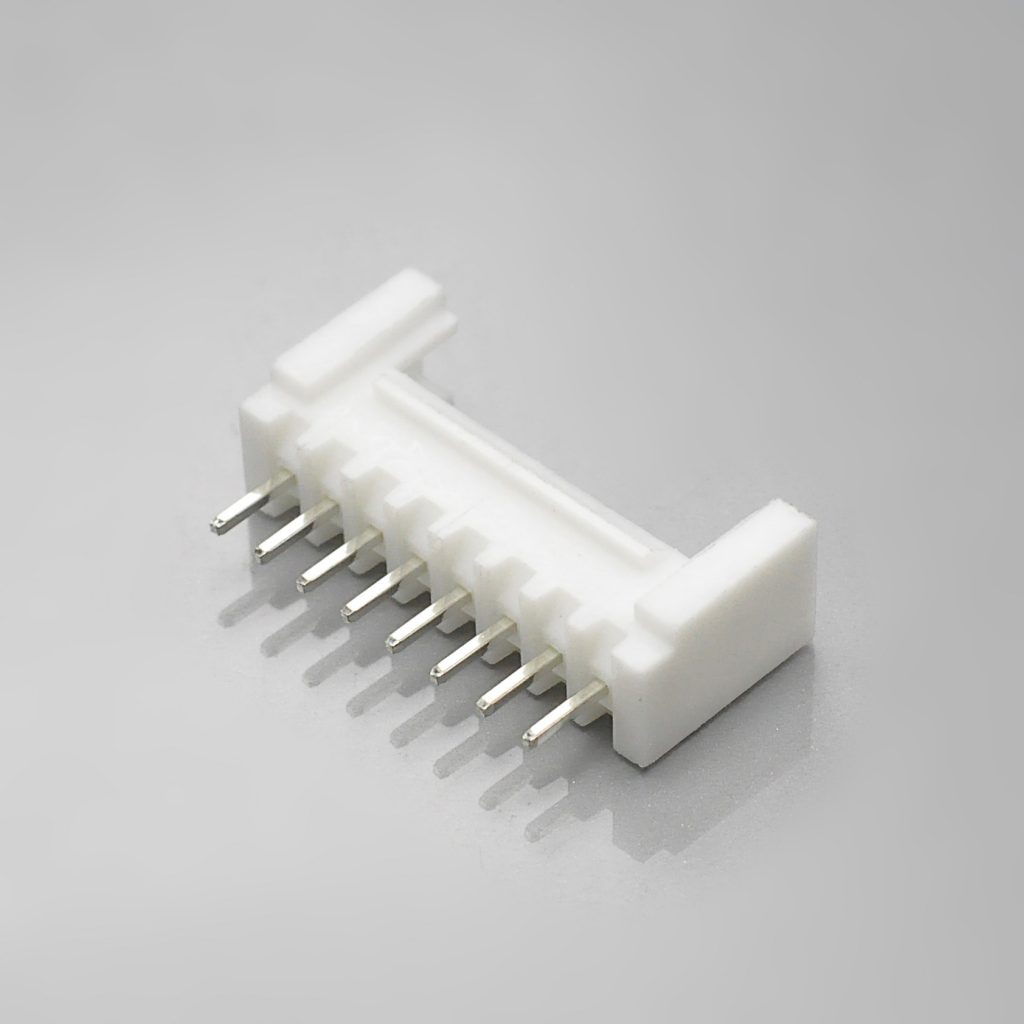
KR2004 DIP straight wafer
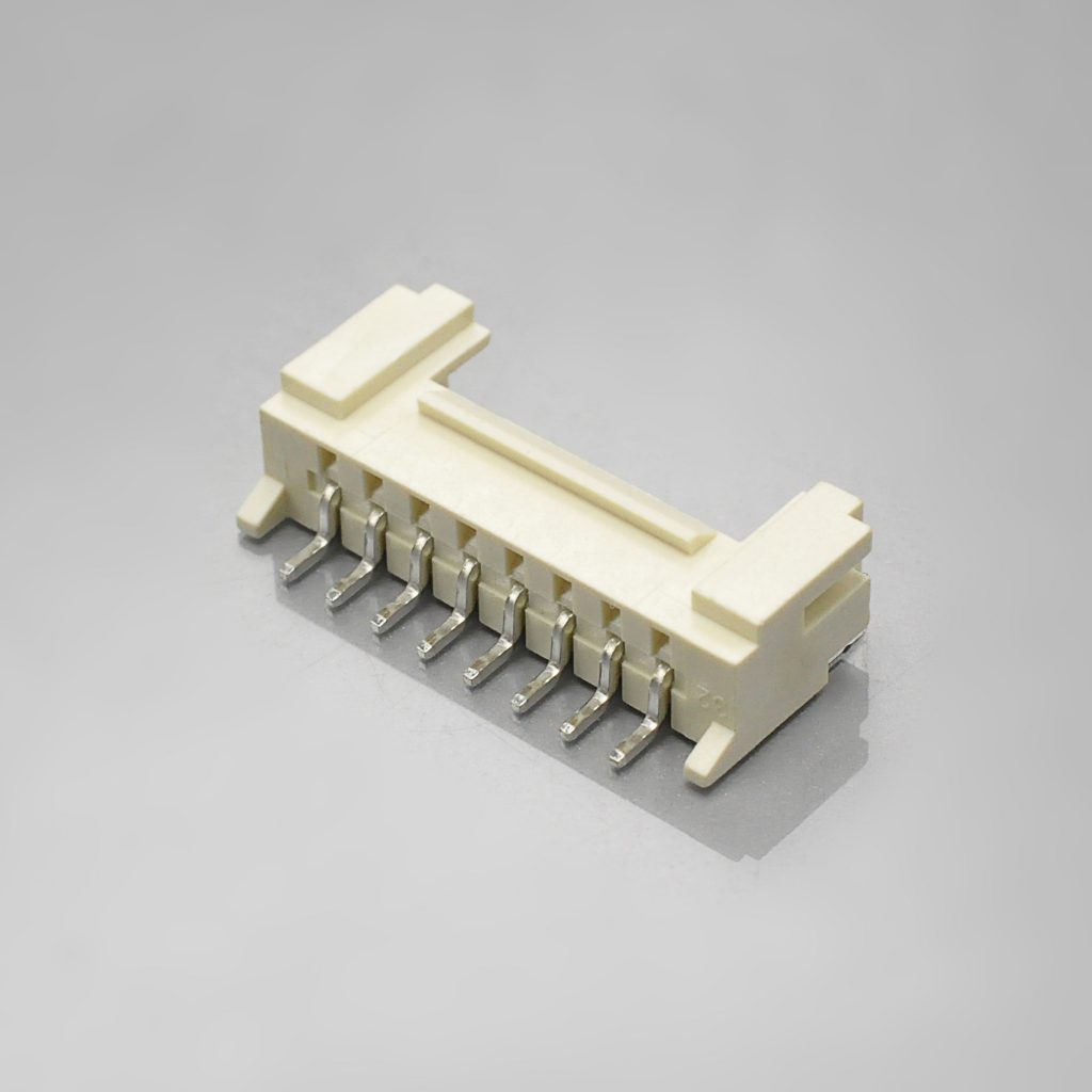
KR2004 SMT right-angle wafer
How to identify whether your connector is this family
The 2.00mm pitch class contains more than a dozen series in KONNRA’s own index, and the locked subset contains several. Work through these in order — the first two questions do most of the work.
1. Measure the pitch. 2.00mm on centres, measured across at least four pitches and divided rather than measured as one gap.
2. Is there a positive lock — a latch that has to be released to unmate? This is the decisive question in this family. A friction connector separates with a steady pull; a locked connector requires the latch to be depressed or lifted first, and usually gives an audible click on mating. KONNRA’s own description of the KR2004 notes a “special configuration that prevents incorrect reverse insertion” in addition to the lock. If there is no latch to release, you are looking at the plain PH 2.0 part (KR2001) rather than this one — and the two share a pitch, a current rating, a circuit range and a name.
3. Count the positions and note the wafer style. This series covers 2 to 16 circuits and is offered in four wafer styles — DIP (through-hole) straight and right-angle, and SMT straight and right-angle. The wafer style is the mounting decision; it does not change the electrical rating.
4. Measure the wire. The range is AWG #22 to #28 with insulation 1.2mm to 1.6mm. The 1.2mm floor is unusually high for this pitch and is the most distinctive measurable feature: a wire with 0.9mm or 1.0mm insulation is outside this part’s window, and that alone separates it from several neighbouring families whose windows start lower.
5. Look at the housing colour if it matters to you. White PA66 is UL94 V-2; blue and yellow are V-0. On a populated board, colour is the fastest available check of which flammability grade you are actually holding.
6. And check the dielectric requirement. This series is specified at 1,000V AC proof voltage, against 800V AC on the plain PH part beside it, and both are 250V-rated. A connector that passes 1,000V and one that passes 800V are not distinguished by appearance; the number is in the documents.
7. If the part is from the market rather than from a drawing, treat the name with suspicion. As the naming section sets out, this family appears under at least four different series names across suppliers, and the published current ratings range from 2A to 5A. A locked 2.00mm connector with a catalogue name is not enough to establish what it is. Measure the pitch, measure the insulation diameter, confirm the lock, and if you need the rating, get a drawing.
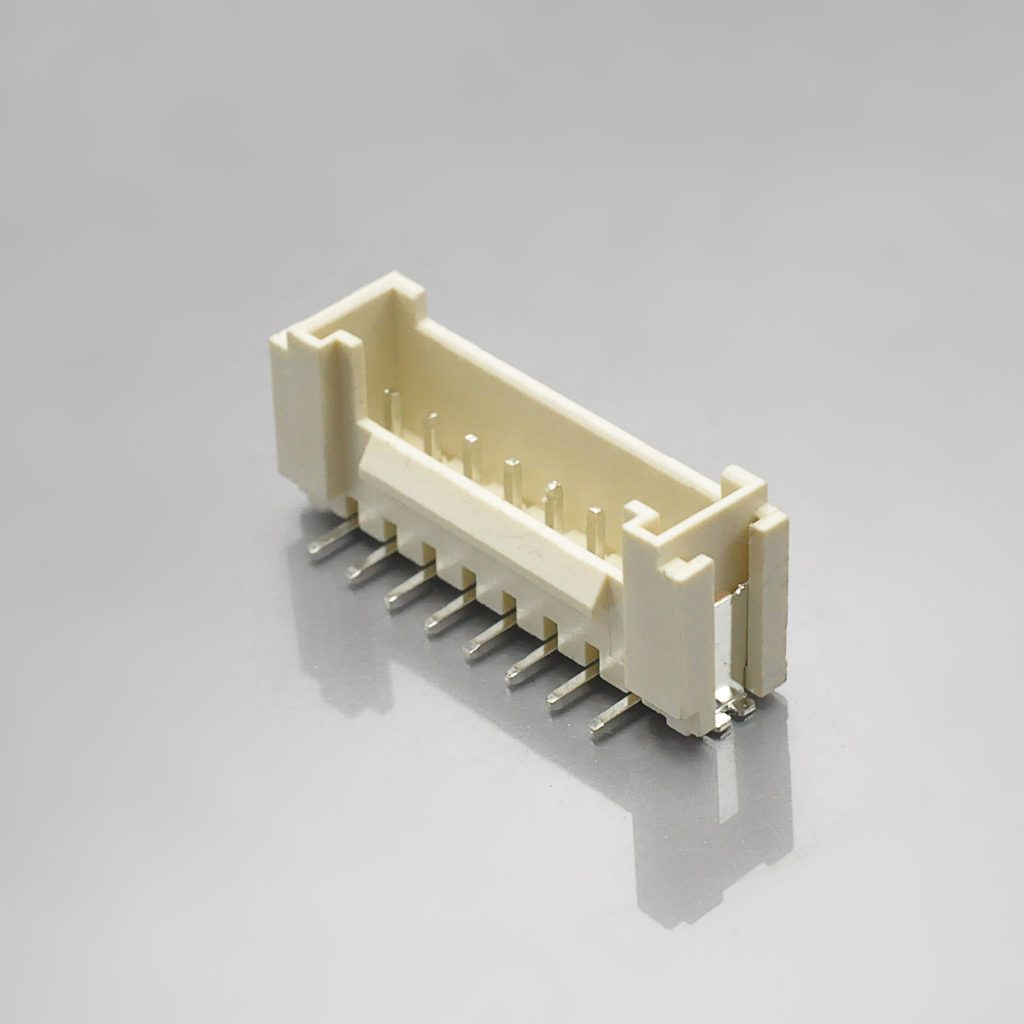
KR2004 SMT straight wafer
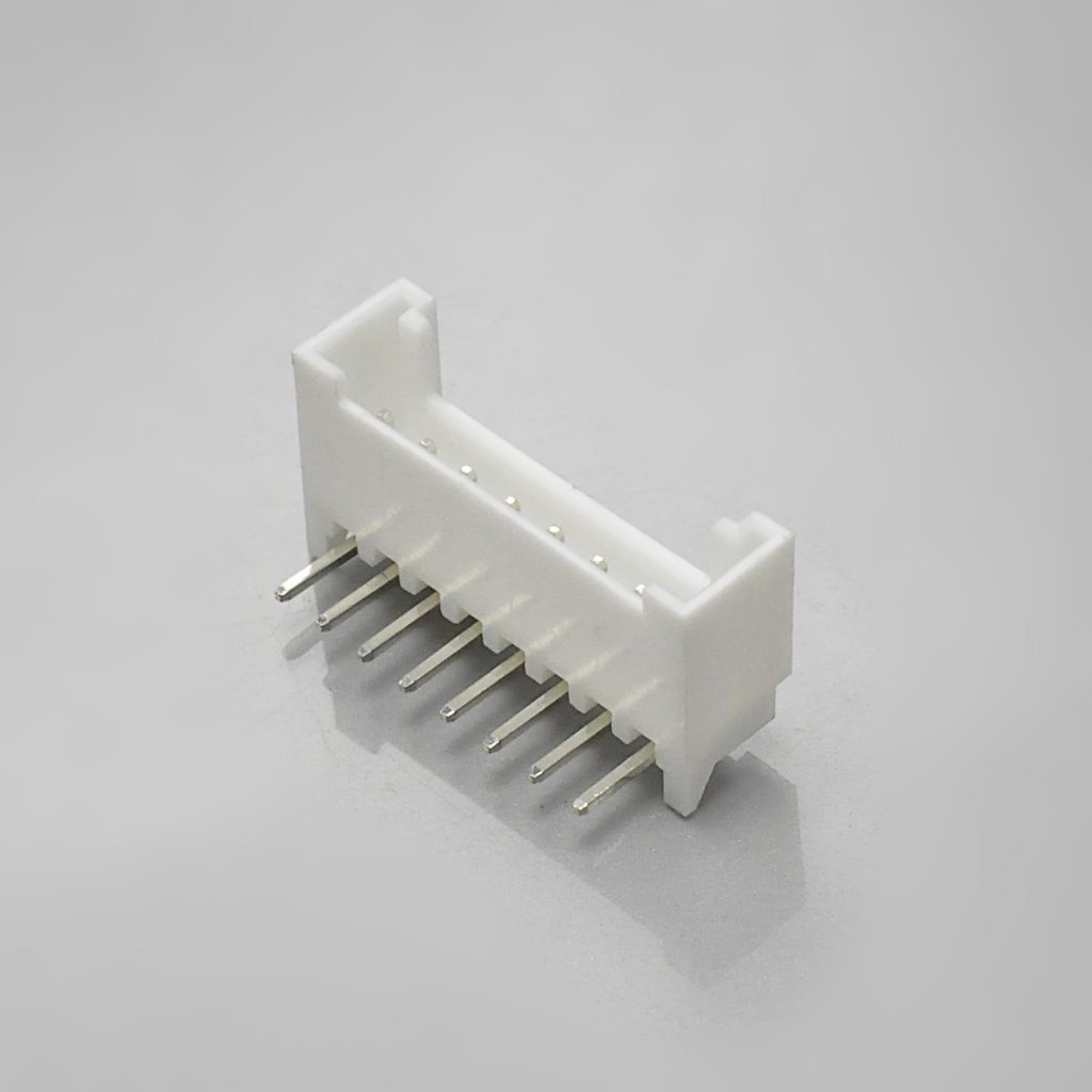
KR2004 DIP right-angle wafer
The environmental programme, and one modest number in it
KONNRA publishes a full environmental section for the KR2004, with the EIA standard named against each test.
| Item | Condition | Requirement |
|---|---|---|
| Durability (§7.1) | 30 cycles at no more than 10 cycles/minute (EIA-364-09C) | Contact resistance 40mΩ max |
| Temperature rise (§7.2) | Carrying rated current load (EIA-364-70B) | 30°C max |
| Vibration (§7.3) | 1.5mm P-P, 10→55→10 Hz in 1 minute, 2 hours per axis in X, Y and Z (EIA-364-28B) | No damage; 40mΩ max; discontinuity 1 microsecond max |
| Mechanical shock (§7.4) | 490 m/s² (50g), 3 strokes in each of 6 directions (EIA-364-27B) | No damage; 40mΩ max; discontinuity 1 microsecond max |
| Heat resistance (§7.5) | 105 ± 2°C, 96 hours (EIA-364-17B) | No damage; 40mΩ max |
| Cold resistance (§7.6) | −40 ± 2°C, 96 hours (EIA-364-59) | No damage; 40mΩ max |
| Humidity (§7.7) | 40 ± 2°C, 90–95% RH, 96 hours (EIA-364-31B) | No damage; 40mΩ max; must meet §5.3; insulation resistance 100MΩ min |
| Thermal shock (§7.8) | −40°C 30 min → RT 5 min → +105°C 30 min → RT 5 min, 5 cycles (EIA-364-32B) | No damage; 40mΩ max |
| Salt spray (§7.9) | 8 hours, 35 ± 2°C, 5 ± 1% NaCl (EIA-364-26B) | No damage; 40mΩ max |
| Solderability (§7.10) | 245 ± 5°C, 3 ± 0.5 seconds (EIA-364-52) | ≥95% of immersed area free of voids and pin holes |
| Solder heat resistance (§7.11) | SMT per profile §9.1 (EIA-364-56D); DIP per profile §9.2 (EIA-364-71B) | No damage |
The heat, cold, humidity, thermal-shock, vibration and shock requirements are the standard set you would expect from a serious 2.00mm connector specification, and they are stated with their test standards and their post-test acceptance criteria, which is what makes them usable in a qualification file.
The relative weakness is the salt spray figure: 8 hours. That is a shorter exposure than other series in the same catalogue — the plain PH 2.0 part specifies 24 hours, and a board-in 2.00mm series we documented specifies 48 hours at the same salt concentration and temperature.
That is worth weighing against what the product is marketed for. KONNRA’s own Overview describes this connector as built for “harsh environments such as the heat and vibration common in heavy equipment vehicles and battery applications.” Heat and vibration are covered by the programme above. Salt spray is not the same kind of requirement — salt exposure is about corrosion resistance in marine, coastal or road-salt environments, and 8 hours is a modest bar. If your application involves that kind of exposure, the 8-hour figure is the number to raise with us, because a longer exposure may require a different plating, a different housing, or a different series entirely.
And there is one thing the specification does not publish: a UL or CSA file number. Other series in this catalogue do carry a published UL file number on their component pages. This one does not. If your product requires a recognised component, ask for the certification status of the specific part number rather than assuming, and note that the requirement may push you toward a specific insulator material or colour (see the flammability section above).
Process windows
KONNRA publishes both soldering profiles in §9.0, which is more than some series in this catalogue provide:
| SMT infrared reflow (§9.1) | Wave soldering (§9.2) | |
|---|---|---|
| Peak temperature | 255 ± 5°C, 5–10 seconds | 250°C max, 3–5 seconds |
| Time at minimum 230°C / 217°C | 20–40 seconds at ≥230°C | 60–150 seconds at ≥217°C |
| Reflow zone | 90–120 seconds | 60–180 seconds |
| Pre-heat | 150–200°C | 150–180°C |
KONNRA adds the note that matters most: “Please check welding conditions by your own devices beforehand. Because the condition changes by the soldering devices, P.C.boards, and so on.”
The two profiles line up with the two wafer families — §9.1 applies to the SMT wafers and §9.2 to the DIP wafers, and §7.11 references them by number. If you are running both mounting styles on one board, note that they have different pre-heat ceilings (200°C versus 180°C) and that the DIP profile reaches 217°C, not 230°C.
Where this part sits in the 2.00mm class
KONNRA’s own 2.00mm index lists more than fifteen series spanning a 2.5× range in current and a 2.5× range in voltage. The table below uses KONNRA’s published cross-reference positioning, so the entries are the supplier’s own:
| KONNRA series | Cross-references to | Architecture | Current | Voltage | Circuits |
|---|---|---|---|---|---|
| KR2004 | YEONHO YH200 PH 2.0 | Wire-to-board with lock | 2A (at AWG #22) | 250V | 2–16 |
| KR2001 | JST PH 2.0 | Wire-to-board, friction | 2A (at AWG #24) | 100V | 2–16 |
| KR2002 | IL-S | Wire-to-board | 2A | 100V | 2–16 |
| KR2003 | JST SAN 2.0 | Board-in | 2A | 250V | 2–16 |
| KR2000 | Molex MicroBlade mx2.0 | DIP wire-to-board | 2A | 125V | 2–15 |
| KR2005 | JST PHD 2.0 | Wire-to-board, 2 rows | 3A | 250V | 2*2–2*20 |
| KR2007 | Molex mx2.0 | Wire-to-wire | 2A | 125V | 2–16 |
| KR2009 | Hirose DF3 | Wire-to-board | 3A | 250V | 2–15 |
| KR2014 | JST PA 2.0 | Wire-to-board | 3A | 250V | 2–15 |
| KR2017 | Molex DuraClik mx2.0 | Wire-to-board | 3A | 125V | 2–14 |
| KR2022 | JST PAL 2.0 | Wire-to-board | 3A | 250V | 2–14 |
| KR2023 | JST ULH 2.0 | Wire-to-board, TPA | 5A | 100V | 2–10 |
Four observations worth carrying into a design review.
Only two entries in this table have a positive lock, and both cross-reference YEONHO. The KR2004 (this part) and, on the 2.5mm pitch, the KR2502 — which KONNRA lists as “KR2502 Series YH 2.5 Wire to Board Connector with Lock.” Every other 2.00mm entry in the table is either a friction type or a board-in type. So if retention is a primary requirement at 2.00mm, the locked option in this catalogue is this one, and the rest of the table is eliminated before you compare a single electrical parameter.
And that makes the KR2001/KR2004 pair the most confusable pair in the whole table. They share a pitch (2.00mm), a circuit range (2–16), a current rating (2A) and a voltage rating (250V) — and one of them has a lock and the other does not. They differ on the cross-referenced original (JST PH versus YEONHO YH200), on the dielectric strength (800V versus 1,000V), and on the qualified wire gauge (#24 versus #22). On a purchase order, the series number is the only thing distinguishing them. Confirm which of the two you are quoting, and confirm it by number rather than by description.
The KR2004 sits in the high-voltage half of the class. At 250V it joins the KR2003, KR2005, KR2009, KR2014 and KR2022, and sits well above the 100V entries (KR2001, KR2002, KR2023) and the 125V entries (KR2000, KR2007, KR2017). Combined with its 1,000V AC dielectric strength — the highest proof voltage in the table — this is a part sized for mains-adjacent and battery systems rather than for logic-level signal runs alone.
And the wire gauge is what separates it from its nearest neighbour in practice. The KR2001’s 2A is qualified at AWG #24 with a range starting at #24; the KR2004’s 2A is qualified at AWG #22 with a range starting at #22. On the same pitch at the same nominal current, this part accepts one gauge heavier. If your harness is AWG #22, this is the one of the pair that fits it — and if it is AWG #24–28 with no lock requirement, the other one is the lower-cost answer.
KR2004 SMT wafers — LCP insulator, UL94 V-0
Closing the verification gap: what to send us
This guide is unusual in this catalogue because one side of the comparison is missing. KONNRA’s KR2004 is documented to seven specification pages and six engineering drawings. YEONHO’s documentation for the cross-referenced series was not obtainable, and the third-party sources that describe it disagree with each other by a factor of 2.5 on current rating alone.
That does not make the part unusable. It makes the validation method different: instead of comparing two datasheets, the comparison has to be made against your drawing or your existing part. That is a five-minute job for us and it produces an answer you can file.
Send us any one of these and we will close the gap in writing:
- Your YEONHO drawing or part number — the most direct route. With the original’s drawing we can compare the footprint, the board thickness assumption, the lock geometry and the rated conditions line by line.
- A photograph of the mated pair with a ruler or callipers across the pitch — enough to confirm the family and the position count, and to check the lock style.
- Your existing harness specification, including the wire gauge and measured insulation diameter — we will check it against the KR2004’s AWG #22–28 range and 1.2–1.6mm window, and tell you plainly if it falls outside.
- Your load and environment — the working current, the ambient temperature and whether salt or road-salt exposure applies. The last one matters because of the 8-hour salt-spray figure discussed above.
And four things we will confirm rather than leave you to infer:
- The applicable board thickness and the recommended PCB layout for your specific part number, against the current drawing. The DIP drawings carry a ±0.05mm recommended layout tolerance.
- The exact orderable part number, including the insulator code — because that code determines whether the housing is UL94 V-2 (white) or V-0 (blue or yellow), and only the drawing’s part-number form can express it.
- Whether your requirement can be met on a DIP wafer at all if your specification calls for UL94 V-0, since the DIP 180° wafer is published in V-2 colours only.
- The lock’s contribution to mating force, which the published force table deliberately excludes — so that your assembly ergonomics and your mating-force budget are sized on the real number.
And if the answer is that this part does not fit your requirement, we will say so and point you at the alternative rather than at a catalogue page. On this pitch the alternatives are in the table above: the unlocked KR2001 for AWG #24–28 friction retention, the KR2003 for a board-in design with no wafer at all, and the KR2023 for 5A.
Cross-reference checklist: ten things to verify before you commit
Work through these in order. Each one corresponds to a specific gap, difference or open question identified in this guide — and because the original’s documentation was not obtainable, the first item is the one that unlocks the rest.
| # | Check | Why |
|---|---|---|
| 1 | Get the original’s drawing, or send us yours | YEONHO’s documentation for this series could not be located, and third-party listings disagree by a factor of 2.5 on current rating. The paper comparison cannot be closed without the original’s drawing — it is the first and most important step. |
| 2 | Confirm you need the locked variant at all | The neighbouring KR2001 shares this part’s pitch, circuit range, current rating and 250V rating, and cross-references JST PH 2.0 instead. If you do not need positive retention, the unlocked part is the lower-cost answer. Confirm by series number, not by description. |
| 3 | Take the wire range from the specification, not the Overview | PS-KR2004-01 §4.0 and the terminal drawing both say AWG #22–28. The product page’s Overview says AWG #24–28, which drops the gauge the 2A rating is qualified at. |
| 4 | Measure your wire’s insulation diameter | The window is 1.2mm to 1.6mm — a window, not a ceiling, and an unusually high floor for this pitch. A wire with 0.9mm or 1.0mm insulation is outside this part’s range. |
| 5 | Raise the current rating if your requirement exceeds 2A | The KR2004 publishes 2A at AWG #22, tested to a 30°C maximum temperature rise. Third-party sources publish 3A and 5A for related YEONHO 2.0mm families. Which applies to your original is unresolved and must be settled against a drawing. |
| 6 | If UL94 V-0 is required, order the right colour — or the SMT wafer | The housing is V-2 in white (code 03) and V-0 in blue (21) or yellow (46). All SMT wafers are LCP V-0; the DIP 180° wafer is published in V-2 colours only, and only the DIP 90° offers a V-0 option (beige, code 22). |
| 7 | Order from the drawing’s part-number form, and include the insulator code | The specification renders the housing as H2004M101A; the drawing renders it as undefined + insulator + undefined. Only the drawing’s form carries the insulator code — which is what determines the flammability grade. |
| 8 | Check whether you need solder tabs, and therefore SMT | SMT wafers carry phosphor-bronze solder tabs; DIP wafers state “solder tab: None”. Retention on the DIP version is the through-hole solder joints alone. |
| 9 | Budget the lock’s force separately | The specification’s force table is measured “excluding plastic detents” (§6.1). The published insertion force is the contact system only — the real operator force is higher, and by an unstated amount. |
| 10 | Weigh the 8-hour salt-spray figure against your environment | The KR2004’s salt-spray exposure is 8 hours, against 24 hours on the plain PH part in the same catalogue and 48 hours on a board-in series. If salt exposure applies, raise it. |
Items 1, 3 and 6 are the three that most often produce a wrong part or an unfileable document. Item 1 is a missing input you cannot work around; item 3 is a page-versus-specification contradiction; and item 6 is a flammability requirement that a white part will silently fail.
Frequently asked questions from procurement and engineering
Is the KR2004 a drop-in replacement for YEONHO YH200? We cannot tell you that from paper, and we are not going to claim it. The KR2004 is documented to seven specification pages and six engineering drawings, and its rating, materials, dimensions, crimp specification and environmental programme are all published. YEONHO’s documentation for the cross-referenced series could not be located, and the third-party listings that describe related YEONHO 2.0mm families disagree with each other — 5A, 3A and 2A are all published for parts carrying similar names. So the comparison has to be made against your drawing or your existing part, and we will do it in writing. Send the drawing and we will compare the footprint, the board assumptions, the lock geometry and the rated conditions line by line.
What is the actual current rating? 2A AC/DC, qualified at AWG #22, tested to a 30°C maximum temperature rise — and AWG #22 is the largest wire this connector accepts, which is the correct way to publish a rating. The KR2004’s 2A is a conservative figure rather than an aggressive one. Be aware, though, that third-party sources publish 3A and 5A for related YEONHO 2.0mm families, so if your requirement exceeds 2A, the question of what your original is actually rated at needs settling against a drawing rather than a listing.
Does it have a lock? Yes — that is the defining feature of this part and the reason it exists separately from the unlocked KR2001 beside it in the same catalogue. The lock resists the two failure modes a friction joint has: vibration working the pair apart, and handling pulling it apart during assembly or service. Note that it costs an extra assembly step — the operator seats the latch and releases it to unmate — and that the published force table excludes the latch force (see the mating-force question below).
What is the difference between the KR2001 and the KR2004? They are the two most confusable parts in the 2.00mm class. Both are single-row wire-to-board at 2.00mm pitch, both cover 2–16 circuits, both are rated 2A, and both are rated 250V. The differences:
| KR2001 | KR2004 | |
|---|---|---|
| Cross-references | JST PH 2.0 | YEONHO YH200 PH 2.0 |
| Retention | Friction — no lock | Lock |
| Current qualified at | AWG #24 | AWG #22 |
| Wire range | AWG #24–28 | AWG #22–28 |
| Dielectric strength | 800V AC | 1,000V AC |
Order by series number, not by description. “PH 2.0 connector with lock” and “PH 2.0 connector” are one word apart and describe different parts.
What is the wire range, and what insulation diameter? AWG #22 to #28, insulation O.D. 1.2mm to 1.6mm — from both PS-KR2004-01 §4.0 and the terminal drawing. Do not take the range from the product page’s Overview paragraph, which says AWG #24–28 and omits the gauge the current rating is qualified at.
Which wafer should I choose? Four are offered: DIP (through-hole) straight and right-angle, and SMT straight and right-angle. The choice has three consequences beyond mounting:
- Flammability. The SMT wafers use LCP, UL94 V-0. The DIP wafers use PA66 UL94 V-2 in most colours, with a V-0 option only on the DIP 90° wafer (beige, code 22). The DIP 180° wafer is published in V-2 colours only.
- Board retention. SMT wafers carry phosphor-bronze solder tabs; DIP wafers state “solder tab: None”.
- Process. The SMT profile peaks at 255 ± 5°C with a pre-heat ceiling of 200°C; the wave profile peaks at 250°C max with a pre-heat ceiling of 180°C.
If your specification requires UL94 V-0 and your board is through-hole, raise it with us — it is a genuine constraint on this series.
What PCB thickness does it suit? The KR2004 specification does not publish an applicable board thickness, and neither does the terminal or wafer drawings beyond their dimensional tables. This is the same gap we have documented on other series in this catalogue. Send us your board thickness and the part number you intend to use and we will confirm it in writing against the current drawing. The recommended PCB layout tolerance is ±0.05mm on both DIP drawings.
How much force does mating take? The published insertion force is 0.60 kgf per circuit — 1.20 kgf at two positions and 9.60 kgf at sixteen. But the specification measures this “excluding plastic detents” (§6.1), so the published figure is the contact system only and the real latch force is additional. If you are sizing an assembly operation or an operator ergonomics limit, budget for the latch separately and ask us for the combined figure.
How many mating cycles, and how much retention is left at the end? 30 cycles, with contact resistance required to stay at or below 40mΩ. On retention: the part loses 0.05 kgf per circuit plus 0.05 kgf across its rated life, so a 2-position connector drops from 0.40 kgf to 0.25 kgf (a 37.5% loss) and a 16-position one from 3.20 kgf to 2.35 kgf (a 26.6% loss). The absolute loss grows with circuit count — the opposite of the pattern on the unlocked part. And remember the lock is additional retention on top of these figures.
Does it survive vibration? The specification requires it to hold electrical continuity to within 1 microsecond through 2 hours per axis at 1.5mm peak-to-peak in all three axes, and to 50g shock in six directions, with contact resistance staying at or below 40mΩ. Combined with the positive lock, that is a substantially stronger retention story than a friction connector’s — which is the reason to specify this part.
What about salt spray? 8 hours at 35 ± 2°C in 5 ± 1% NaCl. That is a shorter exposure than other series in this catalogue — the plain PH 2.0 part specifies 24 hours, and a board-in 2.00mm series specifies 48 hours. KONNRA’s Overview markets this part for “harsh environments such as heat and vibration common in heavy equipment vehicles and battery applications”; heat and vibration are well covered, salt is not. If your application involves marine, coastal or road-salt exposure, raise it.
Is a UL or CSA recognised version available? The KR2004 specification does not publish a UL or CSA file number, and neither does its product page. Other series in this catalogue do carry a published UL file number on their component pages, so this is a documentation gap rather than a statement about the part. Ask for the certification status of the specific part number — and note that if UL94 V-0 is also required, the two requirements may interact (see the wafer question above).
What are the lead time and MOQ? KONNRA can deliver complete connector set samples within 45 days. Connector production lead time is typically 2–3 weeks, and wiring harness assemblies are quoted separately. Terminals are packed 12,000 per reel; MOQ depends on the circuit count, the wafer style and the insulator colour — send the specific configuration and it will be quoted against the actual part numbers.
What else is in this pitch if the KR2004 does not fit? See the pitch-class table above. In brief: the KR2001 for AWG #24–28 with friction retention at 100V; the KR2003 for a board-in design with no wafer at all; the KR2023 for 5A; and the KR2005 for a dual-row requirement. Our other 2.00mm guides cover these in detail — see the JST PH 2.0 connector guide, the JST SAN 2.0 board-in connector guide, the Molex MicroBlade 2.0 connector guide and the Molex CLIK-Mate 1.5 connector guide.
Start your cross-reference check
Send us the four things below and we will come back with a specific answer rather than a catalogue page — including, if you send the drawing, a footprint comparison against the YEONHO part you are replacing:
- Your YEONHO drawing or part number — the single most useful input, because the original’s documentation was not obtainable and the third-party listings disagree
- Your wire gauge and measured insulation O.D. — we will check it against the KR2004’s AWG #22–28 range and 1.2–1.6mm window, and tell you plainly if it falls outside
- Your circuit count and mounting style — and whether your specification calls for UL94 V-0, which constrains the wafer and the housing colour
- Your load and environment — working current, ambient temperature, and whether salt or road-salt exposure applies
From that we can confirm the housing, terminal and wafer part numbers including the insulator code, the applicable board thickness, the recommended PCB layout, the crimp specification, and — where a figure in our published material is thinner than it should be, such as the wire range in the Overview paragraph — give you a written answer against the controlled specification.
- Request a quote — KR2004 pricing, MOQ and configuration for your circuit count, wafer style and insulator colour
- Request a sample — complete connector set samples delivered within 45 days
- Request a cross-reference and footprint check — send your YEONHO drawing or part number and we will compare the footprint, the board assumptions and the lock geometry against the KR2004
- Request a board-thickness and layout confirmation — the applicable PCB thickness and the recommended layout for your specific part number, in writing, against the current drawing
- Request the documents — product specification PS-KR2004-01 (PDF), engineering drawings: housing, terminal and four wafers (PDF) and package specification (PDF)
- Request a crimp specification sheet — conductor and insulation crimp heights, widths and pull-strength requirements for 22, 24, 26 and 28 AWG, with the stripping length
- Request a flammability and material sheet — the UL94 grade by housing colour and by wafer style, so that a V-0 requirement is satisfied on paper before the parts arrive
- Request a vendor qualification pack — test capability summary, quality documentation and certification status for the specific part numbers
- Request assembled harnesses — KR2004 assemblies crimped and tested to the specification above
- Submit a drawing for review — we will flag any specification mismatch before you commit tooling
Contact KONNRA Electronics
- Phone: (86)-769-85449875
- Email: info@konnra.com
- Address: No.6 Nanchang South Road, Chijiao, Wangniudun, Dongguan, Guangdong, China
- Contact us
Orderable components: KR2004 DIP Right Angle Wafer · KR2004 DIP Straight Wafer · KR2004 SMT Right Angle Wafer · KR2004 SMT Straight Wafer · KR2004 Housing with Buckle · KR2004 Terminal
➡️ Explore the full 2.0mm pitch range · Wire-to-Board connector category · YEONHO cross-reference series · JST connector cross-reference: 20+ series
Sources and method
This guide documents KONNRA’s own published specifications for the cross-reference part in full, and states plainly where the original manufacturer’s documentation could not be obtained. No figure attributed to YEONHO is presented as verified, because no YEONHO document was retrieved; third-party claims are labelled as third-party.
Cross-reference manufacturer (KONNRA) — KR2004 series:
- Product specification PS-KR2004-01, Edition A1, issued and revised 2022/2/26, Engineering Dept., Dongguan Konnra Electronics Co., Ltd, seven pages, titled “2.00mm Pitch KR2004 Series Wire To Board Connector Specification.” Hosted at two paths (
PS-KR2004-01.pdfandPS-KR2004-WTB.pdf); the two files were retrieved and compared and are the same document. Used for: §2.0 the part-number table (housingH2004M1****01A; terminalT2004FPT01**A; wafersC2004VD*****T0101PA,C2004RD*****T0101PA,C2004RS***13T0101RC,C2004VS***13T0101RC); §3.0 materials and surface treatment including the housing as PA66 UL94 V-0 or 2, the terminal as phosphor bronze, tin-plated over nickel, the SMT wafer base as LCP UL94 V-0 with a phosphor-bronze solder tab, and the DIP wafer base as PA66 UL94 V-2 with “Solder tab: None”; §4.0 ratings (250V AC/DC, 2A(22AWG) AC/DC, −40°C ~ +105°C, AWG 22#–28# with insulation O.D. 1.2 to 1.6mm); §5.1 contact resistance 20 milliohms max by dry circuit at 20mV / 100mA to EIA-364-23C; §5.2 insulation resistance 1000 megohms min at 500V DC for one minute to EIA-364-21B; §5.3 dielectric strength 1000V AC for one minute to EIA-364-20A with the criterion “No Breakdown and Flashover”; §6.1 durability at 25.4±3mm/minute “excluding plastic detents” to EIA-364-13D; §6.2 terminal insertion force 1.0 kgf (9.8N) max; §6.3 terminal/housing retention 1.0 kgf (9.8N) min; §6.4 pin retention 1.0 kgf (9.8N) min; §6.5 the crimp specification for 22/24/26/28 AWG including the conductor and insulation crimp widths and heights, the crimp strengths (4.54 / 3.63 / 2.27 / 1.36 kgf min) and the stripping length (1.5–2.1mm); §7.1–7.11 the environmental performance including durability (30 cycles), temperature rise (30°C max), vibration (1.5mm P-P, 2 hours per axis, 1 microsecond maximum discontinuity), shock (490 m/s² (50g)), heat (105±2°C, 96 hours), cold (−40±2°C, 96 hours), humidity (40±2°C, 90–95% RH, 96 hours, with 100 megohms min after), thermal shock (5 cycles), salt spray (8 hours), solderability (245±5°C, 3±0.5s, 95% of immersed area) and solder resistance; §8.0 the insertion and withdrawal force table for 2–16 circuits, initial and at 30 cycles; §9.1 the SMT infrared reflow profile and §9.2 the wave soldering profile; and §10.0 the remark. - Engineering drawings, KR2004 series — the series drawing file contains six drawings: 2004H101-A-S Rev A4 (housing, “PH2.0 Have buckle Housing”, PA66 UL94 V-2, dimension table A/B/C for 2–16 circuits, ordering code
H2004M***0301Awith insulator codes 03 PA66 White V2, 21 PA66 Blue V0, 46 PA66 Yellow V0); 2004TF101-A-S Rev A3 (terminal, “PH2.0 Have buckle Terminal”, phosphor bronze, tin over nickel, applicable wire AWG #28~#22, insulation O.D. 1.2 to 1.6mm, 12,000 PCS per reel); 2004WRD101-A-S Rev A04 (DIP 90° wafer, PA66 UL94 V-2, brass contact, ordering codeC2004RD***03T0101PA, recommended PCB layout total tolerance ±0.05mm); 2004WVD101-A-S Rev A05 (DIP 180° wafer “No K”, ordering codeC2004VD***03T0101PA); 2004WRS101-C-S Rev A1 (SMT 90° wafer, LCP UL94 V-0, brass contact, phosphor-bronze solder tabs, ordering codeC2004RS***13T0101RC); and 2004WVS101-C-S Rev A2 (SMT 180° wafer, ordering codeC2004VS***13T0101RC). Used for the specification blocks (2A, 250V, −40~+105°C, 1,000MΩ min, 1,000V AC/minute, 20mΩ max), the material and plating blocks, the dimensional tables, the insulator colour and flammability codes, the solder-tab difference between SMT and DIP, the ±0.05mm recommended layout tolerance, the general tolerance block (X.X ±0.30 / X.XX ±0.20 / X.XXX ±0.10 / angle ±2°), and the part-number ordering codes. - KR2004 product page and its six component pages (DIP Right Angle Wafer, DIP Straight Wafer, SMT Right Angle Wafer, SMT Straight Wafer, Housing with Buckle, Terminal). Used for: the page specification table (pitch 2.00mm, circuits 2–16pin, current 2A, voltage 250V); the General Specifaction table (materials, insulation O.D. 1.2–1.6mm, withstanding 1000V AC/minute, temperature −40°C to +105°C, contact resistance 20mΩ max, insulation resistance 1000MΩ min, plating tin over nickel); the Overview paragraph — which states “AWG #24-#28”, contradicting the specification’s AWG #22–28, and which describes the part as built for “harsh environments such as the heat and vibration common in heavy equipment vehicles and battery applications”; the Advantages section; the component links; the document download links; and the image set.
- KONNRA 2.0mm pitch index page and the YEONHO alternatives category page. Used for the cross-reference positioning of the sibling 2.00mm series in the pitch-class comparison table, and for the KR2502 entry described as “KR2502 Series YH 2.5 Wire to Board Connector with Lock.”
Original manufacturer (YEONHO) — documentation NOT obtained:
- No YEONHO datasheet, catalogue or drawing for the series named by the cross-reference was retrieved.
www.yeonho.co.krreturned no content;www.yeonho.comreturned only footer text (privacy policy, email-collection refusal and ethical-compliance links) with no product content extractable. - Third-party sources located, and what each claims — recorded here so the disagreement is visible rather than resolved by preference:
- A clone manufacturer’s listing for YH200 describes an “Alternative Yeonho Yh200 Disconnectable Crimp Style Wire to Board Connector” at 5A AC, DC, 250V, wire range AWG #24–28.
- A clone manufacturer’s listing for YDH200 describes a “Yeonho Equivalent Housing Connector, 2.0mm Wire to Board” at 3A AC, DC with contact resistance 20MΩ max.
- A distributor listing for YST200 describes it as a terminal, “2.00mm, PH series, with lock”, supporting AWG #22 to #30, current rating up to 3A.
- A clone manufacturer describing “YEONHO 2.0mm” rates it 3.0A AC/DC, 250V.
- Distributor and clone listings additionally use the names SMH200 (described as a housing) and SMAW200 / SMW200 (described as a 2.0mm series, also at
2*7dual-row) for parts in the same market segment. - These figures are presented as third-party claims only. They are not attributed to YEONHO, they were not verified against any YEONHO document, and they conflict with each other and with the KR2004’s published 2A. The spread is 2A / 3A / 5A on current and AWG #24–28 / #22–30 on wire range.
Not published in any source reviewed: an applicable PCB thickness for the KR2004 (beyond the dimensional tables); a UL or CSA file number for the KR2004 in the specification or on the product page; the lock’s contribution to mating force (the force table is measured excluding plastic detents); mounting height and width for the KR2004; and any YEONHO specification whatsoever for the cross-referenced series.
Two internal inconsistencies are reported rather than resolved: the product page’s Overview states AWG #24–28 where the specification and the terminal drawing both state AWG #22–28; and the product page’s part-number table renders the housing as H2004M101A while the housing drawing renders it as undefined + insulator + undefined, a structurally different form that — unlike the specification’s — carries the insulator code that determines the flammability grade. One dimensional error is identified as an error rather than only an observation: the SMT 90° wafer table publishes 16.80 for the A dimension at sixteen circuits, where the column’s own 2.00mm progression and the SMT 180° wafer table both require 36.00; the correct figure is reported as 36.00 and the published 16.80 is flagged as a transcription error, with the underlying drawing recommended as the governing document.
Method note. The KR2004 force tables were analysed as sequences rather than as isolated values. Three exact laws were found with no exceptions across the 2-to-16 range: insertion force = 0.60 × circuits, initial withdrawal force = 0.20 × circuits, and post-30-cycle withdrawal force = 0.15 × circuits − 0.05. The retention loss derived from those laws — 0.05 × circuits + 0.05 kgf — was found to grow with circuit count, and this is reported as a contrast with the fixed-loss behaviour documented on other series in this catalogue rather than as an error. The insertion and withdrawal force laws published for the neighbouring unlocked part were then compared against these, producing two cross-overs at exact position counts (15 circuits for insertion, 3 circuits for withdrawal), and those intersections are reported as published-data observations with an explicit caution that they are not grounds for substituting one connector system for the other. The six engineering drawings were transcribed and their dimensional columns checked for internal consistency, which is how the 16.80 / 36.00 error was identified; the SMT and DIP material blocks were compared, which is how the solder-tab difference and the colour-dependent flammability grades were identified. The YEONHO side of this comparison is left open rather than approximated. Where a figure could not be verified against the original, the at-a-glance table marks it “not verified” instead of presenting a third-party claim as a specification.