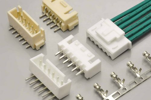
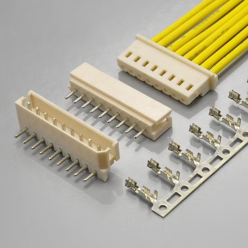
Quick answer: The JST SM is a 2.5mm pitch, crimp-style, disconnectable wire-to-wire connector with a high-pressure contact, an arm lock mechanism and panel-mount capability, rated 3A and 250V AC/DC, running from −25℃ to +85℃. Its withstanding voltage is 1,500 VAC/minute, its insulation resistance is 500MΩ minimum, its contact resistance is 10mΩ maximum initially and 20mΩ after environmental tests, and it accepts AWG #28 to #22 with insulation from 1.2mm to 1.8mm. The KONNRA KR2507 is the cross-reference equivalent, and it is the closest electrical match in the 2.5mm family: all five of those figures match exactly — the 1,500V withstand, the 500MΩ insulation resistance, the 10mΩ initial contact resistance, the 250V/3A ratings and the AWG #28–#22 wire range. Two things do not match. The KR2507’s housing is documented as PA66 UL94 V-2, where JST specifies PA 6 at UL94V-0 — a genuinely weaker flammability rating, and the one finding in this guide that a safety reviewer will stop on. And the insulation window is published as 1.6mm Max against JST’s 1.2mm to 1.8mm, so it is narrower at the top and has no published floor.
The wire-to-wire member of the 2.5mm family
Every cross-reference in this series so far has been a board connector. The SM is not. JST’s own catalogue introduces it as “2.5 mm pitch / Disconnectable Crimp style wire-to-wire connectors”, and describes them as connectors “that perform reliably in high-density, small current applications.”
That single fact changes what a complete connection looks like, and it is the first thing to get right:
| Wire-to-wire (JST SM pattern) | Wire-to-board (the other 2.5mm families) | |
|---|---|---|
| A complete connection | Two housings and two crimp terminals | One housing, one crimp terminal and a PCB wafer |
| Mounts to | The other half of the cable — or a panel cut-out | A printed circuit board |
| Wafer / header | None | Required, in DIP or SMT |
| Soldering | None — nothing is soldered | Wave or reflow profile required |
| Typical use | Inline cable joins, panel-mounted ports, LED strip feeds | Board-to-module wiring |
Read that table as a warning to whoever is cross-referencing. A wire-to-wire part has no wafer, no solder joint and no reflow profile, so a specification for one correctly contains none of those sections. It does not mean the document is incomplete.
And it is worth saying plainly: SM and XH are not interchangeable. Both are 2.5mm pitch, both are 3A and 250V — and one mates two cables while the other mates a cable to a board. They do not mate with each other, and no amount of datasheet similarity changes that.
What the JST SM 2.5 Connector Is
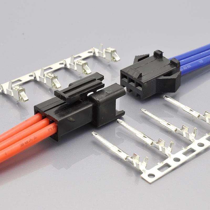
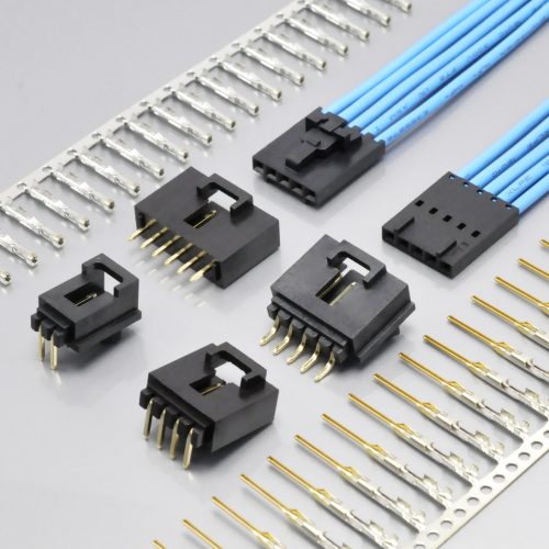
KONNRA KR2507 series SM 2.5 wire-to-wire electrical connector plug, the cross-reference for the JST SM 2.5
JST’s catalogue leads with four features, and each one describes a physical design decision:
- “High contact pressure” — the contact geometry is chosen to hold pressure on the mating blade, which is why the family is used where vibration and handling matter
- “Highly reliable housing construction” — the housing is built around the retention of the crimped contact, not just around the contact cavity
- “Mountable on a variety of panels” — the SM is a panel-mount connector as well as an inline one, and JST publishes the panel cut-out dimensions for it
- “Arm lock mechanism” — the two halves latch, and the closure is an arm rather than a friction fit
JST adds one useful operating note: “SM connectors with any number of circuits can be used either panel mounted or free hanging.” That is worth knowing, because it means the panel-mounting feature is not restricted to a subset of circuit counts.
Two contacts, and the gender naming is the thing to watch.
| JST contact | Role | Pairs with |
|---|---|---|
SYM-001T-P0.6 |
The pin contact | The receptacle housing, SMR-… |
SHF-001T-0.8BS |
The socket contact | The plug housing, SMP-… |
Read the pairing carefully, because it is inverted from the naming that most people carry in their head. In the SM family the plug housing takes the socket contact, and the receptacle housing takes the pin contact. If you order by the word “plug” and assume it takes a pin, you will order the wrong contact. Both contacts are phosphor bronze, tin-plated with a reflow treatment, and both are supplied on reels — 8,500 pieces for the pin contact, 5,000 for the socket contact.
And JST publishes the tooling, part number by part number. The crimp machine is the AP-K2N, with applicators named per contact — MK/SYM-001-06 or MKS-L with dies APLMK SYM001-06 for the pin contact, and MK/SHF-001-08S or APLMK SHF001-08S for the socket contact. That level of detail is the difference between a harness shop being able to set up and having to experiment.
The KONNRA KR2507 Part Numbers
PS-KR2507-01 §2.0 lists five production part numbers, and one row is worth reading closely:
| Component | KONNRA part number |
|---|---|
| Housing — socket side | H2507F***0401C |
| Housing — pin side | H2507M***0401C |
| Terminal — pin contact | T2507MPT0101C |
| Terminal — socket contact | T2507FPT0101C |
| Wafer | None |
“Wafer: None” is the correct answer, not a gap. The KR2507 is a wire-to-wire connector, so there is no board-side component — and the specification states that explicitly in its own part-number table rather than leaving a blank. The material section then carries the same statement through: every wafer row (straight and right-angle, base, contact and solder tab) reads “N/A”.
That is a documentation decision worth crediting, because it is the opposite of the failure mode a cross-reference usually has — a specification copied from a board connector that keeps wafer sections no one can fill in. This one is typed to the product.
The four components also map cleanly onto JST’s:
| KR2507 component | JST SM equivalent |
|---|---|
Male Housing H2507M***0401C |
Plug housing SMP-…V-B(N)C |
Female Housing H2507F***0401C |
Receptacle housing SMR-…V-B / -N |
Male Terminal T2507MPT0101C |
Pin contact SYM-001T-P0.6 |
Female Terminal T2507FPT0101C |
Socket contact SHF-001T-0.8BS |
One naming warning before you read the tables. Look at the suffix letters: hg is the Male Housing and hm is the Female Housing; tg is the Male Terminal and tm is the Female Terminal. So hg and hm do not stand for “male/female housing” in the obvious order, and neither do tg and tm. On the KONNRA side, go by the words “Male” and “Female” on the component page, not by the two letters in the URL. If a harness shop orders by suffix letter alone, this is the family where that goes wrong.
Key Specifications at a Glance
| Attribute | JST SM (manufacturer) | KONNRA KR2507 | Verdict |
|---|---|---|---|
| Pitch | 2.5mm | 2.50mm | Match |
| Configuration | Wire-to-wire, crimp, disconnectable | Wire-to-wire, crimp | Match |
| Wafer | None | None | Match |
| Lock | Arm lock mechanism | Friction lock / “safety locking mechanism” | Same intent |
| Panel mounting | Yes — panel cut-out dimensions published | Yes — “mountable on a wide range of panel thicknesses without tools” | Match |
| Current rating | 3A AC/DC max. | 3A (22AWG) | Match |
| Voltage rating | 250V AC/DC max. | 250V | Match |
| Withstanding voltage | 1,500 VAC/minute | 1500V AC/ minute | Match |
| Insulation resistance | 500MΩ min. | 500MΩ Min | Match |
| Contact resistance, initial | 10mΩ max. | 10mΩ Max | Match |
| Contact resistance, after environmental tests | 20mΩ max. | 20mΩ Max on §7.1–7.6; 40mΩ Max on §7.7–7.9 | Partial — see below |
| Applicable wire | AWG #28 to #22 (0.08–0.33mm²) | AWG 22# to 28# | Match |
| Insulation O.D. | 1.2mm to 1.8mm | 1.6mm Max | Narrower, and no floor |
| Temperature range | −25℃ to +85℃ (including temperature rise under load) | −40℃ to +105℃ | Wider by 20℃ / 15℃ |
| Circuits | 2 to 12, and 18 | 2 to 16 | Different at both ends |
| Current at the top count | 2A at 18 circuits | Not published above 16 | Original only |
| Applicable panel thickness | 0.5mm to 2.0mm | Not published | Original only |
| Housing material | PA 6, UL94V-0 | PA66 UL94 V-2 | Weaker flammability rating |
| Colour | Black and white (natural) | Black | Partial |
| Terminals published | 2 (SYM-001T-P0.6, SHF-001T-0.8BS) |
2 (T2507MPT0101C, T2507FPT0101C) |
Match |
| Crimp tooling published | Crimp machine and applicators named per contact | Crimp dimensions only | Original only |
| Agency | Recognized E60389, TÜV R50120150, RoHS2 | UL E482542 | Partial |
Both columns come from manufacturer documents. Sources are listed at the end.
The Five Ratings That Match Exactly
This is the strongest part of the comparison, and it is stronger than in any of the neighbouring 2.5mm cross-references. Five figures agree to the digit, and they include the two that are hardest to get right.
| Figure | JST SM | KONNRA KR2507 |
|---|---|---|
| Withstanding voltage | 1,500 VAC/minute | 1500V AC/ minute |
| Insulation resistance | 500MΩ min. | 500MΩ Min |
| Contact resistance, initial | 10mΩ max. | 10mΩ Max |
| Applicable wire | AWG #28 to #22 | AWG 22# to 28# |
| Current / voltage rating | 3A / 250V AC/DC max. | 3A / 250V |
Why these five matter more than a headline rating. Each of them is a figure where a cross-reference normally drifts by a comfortable margin, and the drift is invisible until a qualification test:
- The withstanding voltage is 1,500V — one and a half times the 1,000V of the neighbouring board families, and the KR2507 matches it. A supplier writing a safe datasheet would have put 1,000V. Ours says 1,500V, and JST’s says 1,500V.
- The insulation resistance is 500MΩ — deliberately half the 1,000MΩ that the neighbouring KONNRA series publish, and the KR2507 matches JST’s 500MΩ rather than the house figure. That is the strongest single piece of evidence in this comparison: a copied specification would have carried 1,000MΩ across, and this one did not.
- The initial contact resistance is 10mΩ — again half the 20mΩ the neighbouring series publish, and again matched to the original. A 10mΩ limit is a demanding claim, and it is the original’s claim, not ours.
- The wire range is AWG #28–#22 on both sides, so a harness already built on 26 or 28 AWG does not need a wire change.
- The 3A and 250V ratings match, and the KR2507’s specification references the 3A to 22 AWG — the same reference conductor JST uses.
Taken together, those five figures say something specific about the document. The KR2507’s electrical sheet was written against the JST SM and not against KONNRA’s own house template — because on three of the five, the house template would have produced a different number. That is worth knowing when you are deciding how much of the rest of the sheet to trust.
One partial exception, and it is architectural rather than clerical. JST publishes a single post-conditioning contact-resistance limit of 20mΩ after environmental tests. The KR2507 publishes 20mΩ for the five environmental tests that measure contact resistance up to §7.6 — durability, vibration, shock, heat and cold — and 40mΩ for the last three: humidity (§7.7), thermal shock (§7.8) and salt spray (§7.9). (§7.2 measures temperature rise rather than contact resistance, so it is not part of this count.) So five tests match the original exactly and three allow twice that.
Which reading is right depends on what you are designing for. If your qualification is humidity, thermal shock or salt spray, the KR2507’s permitted drift is twice what JST publishes. If it is any of the other six, the two documents agree to the digit. Ask for the actual measured values for the specific conditioning your product has to survive rather than comparing the two limits.
Which brings us to the two places where this cross-reference is genuinely different — and the first one is not a documentation matter at all.
The Flammability Rating: V-2 Against V-0
This is the finding in this guide that a safety reviewer will stop on, and it is not a documentation defect. It is a difference in the parts.
| Source | Housing material and flammability |
|---|---|
| JST SM catalogue | Housing material: PA 6, UL94V-0 |
| KONNRA KR2507 specification §3.0 | /Housing PA66 UL94 V-2 |
| All four KR2507 component pages | Material: PA66 UL94 V-2 |
| KR2507 product page | General Specification lists material as PA66/UL94 (no grade given) |
UL 94 has a scale, and V-0 and V-2 are at different points on it. The short version, in the direction that matters here:
| Rating | Vertical burn test — how long the specimen keeps burning after the flame is removed | Ignition of a cotton indicator below the specimen |
|---|---|---|
| V-0 | Self-extinguishing quickly | Not permitted |
| V-1 | Self-extinguishing, somewhat longer | Not permitted |
| V-2 | Self-extinguishing, similar duration | Permitted |
The difference between V-0 and V-2 is the cotton indicator. A V-2 material may drip burning particles that ignite a cotton pad placed below the specimen; a V-0 material may not. Everything else about the two ratings is close. V-2 is a weaker rating than V-0, and it is the weaker rating that the KR2507 is documented at.
Three things follow, and they are worth separating.
First, be precise about what this is and is not. V-2 is a valid UL 94 rating and a great many production connectors use it. It is not a defect and it does not mean the part is unsafe in most applications — a 2.5mm wire-to-wire connector inside an enclosure, behind a panel, running at 250V and 3A with an arm lock, is not obviously in a high ignition-risk position. What it does mean is that the cross-reference is not like-for-like on a rating that customer specifications routinely call out, and it is exactly the kind of difference that only appears when someone opens the two datasheets side by side.
Second, the house document is what says V-2 — and it says it consistently. The KR2507 specification’s material section and all four component pages each read PA66 UL94 V-2. So this is not a typo on one page; it is the documented material for the series. And note the pattern by contrast with the board families in the same range: the KR2501, KR2502 and KR2504 specifications all document UL94 V-0 for their housings. Only the KR2507 is documented at V-2.
Third, the product page does not tell you. Its General Specification row reads “PA66/UL94” with no grade — the one place on the site where the grade is omitted for this series.
What to do about it: if your product specification, your customer’s requirement or your market’s approval route names UL94 V-0 for the connector housing, do not assume the KR2507 satisfies it — put the question to us in writing at enquiry stage and we will answer it against the drawing and, where relevant, the UL file. If nothing in your requirement set names a grade, this section is information rather than a blocker.
And one positive that sits right next to it. JST documents the SM housing in black and white (natural); the KR2507 is documented in black. Isolation and identification by colour is therefore available at the count people usually need — but if a design colour-codes a pair of mating cable ends, white is the variant to ask about, because it is the one JST publishes and the one we document only in black.
The Insulation Window: Narrower Than the Original
| Source | Applicable wire insulation O.D. |
|---|---|
| JST SM catalogue (both contacts) | 1.2mm to 1.8mm |
| KONNRA KR2507 specification §4.0 | Insulation O.D. 1.60mm(Max.) |
| KR2507 product page | Insulation O.D 1.6mm Max |
| KR2507 terminal component pages | Insulation Diameter 1.6mm Max |
The upper bound is lower than the original’s, and there is no lower bound at all.
JST publishes a two-sided window of 1.2mm to 1.8mm. The KR2507 publishes a ceiling of 1.6mm — so wire whose insulation measures between 1.6mm and 1.8mm is inside JST’s specification and outside ours, and nothing in the KR2507 documentation states a floor, so the 1.2mm end is unaddressed as well.
Note that this runs the opposite way from a wire-range comparison, and it is easy to conflate the two. The KR2507’s wire range matches JST exactly — AWG #22 to #28, with no gaps. But a wire at the top of the gauge range can still be outside the insulation window, because insulation thickness varies by wire grade, wall thickness and temperature rating at the same conductor size. A harness can be exactly on the right gauge and still not fit.
And the missing floor sits where this family is used. JST’s 1.2mm floor is the fine end, and it pairs with the heavier gauges where the insulation wall is thin. So the KR2507 publishes 1.6mm Max for a window whose lower bound is the number a fine-wall wire depends on.
This is the parameter that fails quietly. An insulation barrel that is too tight for the wire closes on the insulation instead of gripping the conductor; the joint passes a continuity check, ships, and fails in the field. On a panel-mounted part, where the cable is also being pulled through a cut-out and dressed against a panel, the crimp sees more handling than a board connector does — which makes the insulation crimp more important, not less.
What to do: measure the actual insulation O.D. of the wire on your harness drawing — not the nominal, and not the gauge — and confirm it in writing against the contact you are quoting. Because one end of the published window is missing and the other is 0.2mm tighter than the original’s, the datasheet cannot be your safety net for this parameter.
Temperature: 20℃ Wider Than the Original Publishes
| Source | Temperature range |
|---|---|
| JST SM catalogue | −25℃ to +85℃, stated as including the temperature rise in applying electrical current |
| KONNRA KR2507 specification §4.0 | Ambient temperature Range −40~+105 |
| KR2507 component pages | −40℃~105℃ |
The KR2507 documents a range 20℃ wider at the hot end and 15℃ wider at the cold end than the original’s. It is also the same house figure the neighbouring KONNRA series carry, which is what a house rating looks like rather than a part-specific qualification.
And there is a useful cross-check, because it is now the fourth time the same divergence appears. In the JST XH, Yeonho 2.5 and JST EH comparisons, KONNRA documented −40℃ to +105℃ against originals publishing −25℃ to +85℃ — the same 20℃ gap, in the same direction, against three different manufacturers. The JST SM is the fourth. That consistency is not evidence about the KR2507; it is evidence about the house figure, and it is the reason to treat the wider range as a claim to be supported rather than a specification to be inherited.
The supporting tests do exist in the specification, and they are worth requesting by clause: §7.5 heat resistance at 105±2℃ for 96 hours, §7.6 cold resistance at −40±2℃ for 96 hours, and §7.8 thermal shock over 5 cycles between −40℃ and +105℃. If your application runs above +85℃, ask for the heat-ageing report.
Circuits: 2 to 16 Against 2 to 12 and 18
| Source | Circuits |
|---|---|
| JST SM catalogue — plug housing | SMP-02V … SMP-12V, and SMP-18V |
| JST SM catalogue — receptacle housing | SMR-02V … SMR-12V, and SMR-18V |
| JST SM catalogue | 2, 3, 4, 5, 6, 7, 8, 9, 10, 11, 12 and 18 |
| KR2507 product page | 2-16pin |
| All four KR2507 component pages | 2P~16P |
| KR2507 specification §8.0 force table | 2 to 16 |
JST catalogues 2 through 12, and then 18 — with a gap at 13 to 17. The KR2507 documents 2 to 16, continuous. So the two ranges overlap from 2 to 12, and then diverge at both ends of the overlap:
- The KR2507 has no 18-circuit option, which is the one position JST catalogues above 12
- The KR2507 documents 13 to 16, which JST’s published housing list does not cover
And the 18-circuit original carries a derate worth knowing. JST lists 3A for 2 to 12 circuits, and 2A for 18 circuits — the current rating steps down at the top count, which is normal when a connector gets long enough for its own thermal mass and contact spacing to matter. The KR2507’s force table runs to 16 with no published current derate, and there is no 18-way to compare at all. If you are designing at 16 ways and near 3A, ask us what the current rating is at that count rather than assuming it holds at the 2-circuit value.
The KR2507’s own documentation is internally consistent here, which is worth stating: the product page, all four component pages and the specification’s §8.0 force table all say 16. So the extension beyond JST’s 12 is supported end to end, and the only real question is the missing 18-way.
The Mechanical Clauses in PS-KR2507-01
| Clause | What is measured | Requirement |
|---|---|---|
| §6.1 | Insertion and withdrawal force, at 25.4 ±3mm/minute, excluding plastic detents, EIA-364-13D | Refer to §8.0 |
| §6.2 | Terminal insertion force — clicking the crimped terminal into the housing | 1.0 kgf (9.8 N) max |
| §6.3 | Terminal / housing retention force — axial pull out at 25.4 ±3mm/minute | 1.5 kgf (14.7 N) min |
| §6.4 | Terminal crimping specification — the crimp table | See below |
§6.4 is where this specification differs from its neighbours, and it is a difference in the specification’s favour. In the KR2500, KR2501, KR2502 and KR2504 specifications, §6.4 is a pin-to-pin retention force requirement written as “Apply axial push force” — a retention test that cannot be run as written, because a retention force is the force required to separate two parts and therefore a pull. That defect has now appeared in four previous series.
In this specification, §6.4 is the crimp table instead. There is no pin-to-pin retention clause at all, so the wording defect is absent from this document. That is worth noting for two reasons: it shows the defect is a template artefact rather than a universal feature, and it means that when you write a test procedure against the KR2507 you are reading a clause that says what it means.
What the omission also tells you is that the retention story for a wire-to-wire connector is a different story. There is no board-side pin to retain, so the only retention that matters is the terminal in the housing (§6.3) and the two housings to each other (the arm lock). JST’s SM and the KR2507 both put the emphasis there: JST on the arm lock mechanism, and the KR2507’s prose on a friction lock plus a “safety locking mechanism”.
§6.3 is the clause to design against. A terminal-to-housing retention of 1.5 kgf (14.7 N) minimum means a 1.5kg axial pull on the wire is what the terminal must survive inside the housing before it moves. That is lower than the 2.0 kgf the neighbouring KONNRA board series specify, and it is the right order for a smaller, lighter contact. Set it against §8.0, where the minimum withdrawal force for a whole 2-circuit connector is 0.60 kgf — that is 0.30 kgf per contact — and the ratio between the terminal’s grip in the housing (1.5 kgf) and the housing-to-housing grip (0.30 kgf per contact) is about 5:1.
Why 5:1 is the right shape, and why it is a lower number here. The wire must be harder to pull out of the housing than the housing is to unplug from its mate, or a tug on the cable leaves live contacts exposed instead of simply unplugging the connector. For a panel-mounted connector, though, the panel does part of that work — the housing is held by the panel cut-out as well as by the arm lock, so the connector-level withdrawal force does not have to carry the whole load. A 5:1 ratio on a panel-mount part and a 10:1 ratio on a free-hanging board connector are not a comparison of quality; they are two different mechanical situations.
The insertion and withdrawal force table
PS-KR2507-01 §8.0 publishes a per-circuit-count force table in kgf for 2 to 16 circuits.
| Circuits | Insertion force max | Withdrawal force min, initial | Withdrawal force min, after 30 cycles | Circuits | Insertion force max | Withdrawal force min, initial | Withdrawal force min, after 30 cycles |
|---|---|---|---|---|---|---|---|
| 2 | 3.00 | 0.60 | 0.40 | 10 | 7.00 | 2.20 | 2.00 |
| 3 | 3.50 | 0.80 | 0.60 | 11 | 7.50 | 2.40 | 2.20 |
| 4 | 4.00 | 1.00 | 0.80 | 12 | 8.00 | 2.60 | 2.40 |
| 5 | 4.50 | 1.20 | 1.00 | 13 | 8.50 | 2.80 | 2.60 |
| 6 | 5.00 | 1.40 | 1.20 | 14 | 9.00 | 3.00 | 2.80 |
| 7 | 5.50 | 1.60 | 1.40 | 15 | 9.50 | 3.20 | 3.00 |
| 8 | 6.00 | 1.80 | 1.60 | 16 | 10.00 | 3.40 | 3.20 |
| 9 | 6.50 | 2.00 | 1.80 |
The table is internally consistent to two decimal places, and all 45 figures reproduce from three expressions:
- Insertion force maximum = 2.00 + 0.50 × N kgf — 2 circuits gives 3.00, 16 circuits gives 10.00
- Withdrawal force minimum (initial) = 0.20 + 0.20 × N kgf — 2 circuits gives 0.60, 16 circuits gives 3.40
- Withdrawal force minimum (after 30 cycles) = 0.20 × N kgf — 2 circuits gives 0.40, 16 circuits gives 3.20
Every circuit count shows the same 0.20 kgf drop after 30 mating cycles. The insertion force maximum reaches 10.00 kgf — about 98N — at 16 circuits, which is a real number for an inline connector that an operator has to pull apart by hand.
One cross-series observation that is checkable and worth knowing. This table is numerically identical to the KR2501’s and the KR2502’s, circuit count for circuit count, while the KR2504’s table — the low-profile board family — uses a different model (a lower insertion intercept and half the withdrawal slope). So within KONNRA’s 2.5mm range there are effectively two published force models, and the KR2507 sits on the same one as the two board families it resembles in contact size rather than on the one belonging to the family it resembles in pitch.
What that means practically: the KR2507’s documented withdrawal force is higher than the KR2504’s at every circuit count — at 16 ways, 3.40 kgf against 1.80 kgf. For a panel-mounted inline connector that is the direction you want, because the arm lock and the panel cut-out are holding the housing while the operator pulls on the cable.
Crimp and Termination
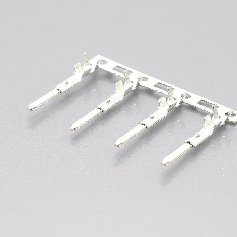
KONNRA KR2507 2.50mm pitch male terminal for the JST SM 2.5 wire-to-wire system
PS-KR2507-01 §6.4 publishes crimp geometry for four wire sizes.
| Parameter | 22 AWG | 24 AWG | 26 AWG | 28 AWG |
|---|---|---|---|---|
| Conductor crimp width | 1.70 ±0.15mm (all four sizes) | |||
| Conductor crimp height | 1.00 ±0.05 | 0.90 ±0.05 | 0.80 ±0.05 | 0.65 ±0.05 |
| Insulation crimp width | 2.00mm max (all four sizes) | |||
| Insulation crimp height | 1.90 ±0.10 | 1.80 ±0.10 | 1.70 ±0.10 | 1.45 ±0.10 |
| Crimp strength | 4.54 kgf min | 3.63 kgf min | 2.27 kgf min | 1.36 kgf min |
| Stripping length | 2.1 – 2.6mm (all four sizes) |
Four observations.
Both crimp ladders run the right way — conductor heights from 1.00mm down to 0.65mm, insulation heights from 1.90mm down to 1.45mm, decreasing as the conductor gets thinner. That direction carries the whole meaning of a crimp table, and a reversed ladder is easy to publish and hard to notice.
The conductor crimp heights are the highest in the 2.5mm family. At 22 AWG the KR2507 specifies 1.00 ±0.05mm, where the KR2501 and KR2502 specify 0.73mm and the KR2504 0.85mm. That is not an error — a different terminal geometry closes to a different finished height — but it is a number that matters to a harness shop, because a setup sheet carried over from another series will be wrong twice over: the height and the strip length both change.
The stripping length is the longest of the family: 2.1 to 2.6mm. The neighbouring board series specify 1.6–2.1mm (KR2501, KR2502) and 1.9–2.7mm (KR2504). Stripping length is the parameter most likely to be copied across without thinking, and a wire stripped to 1.6mm for a terminal that wants 2.1mm leaves the conductor short in the crimp barrel.
And one boundary worth checking on your own wire. The insulation crimp height at 22 AWG is 1.90 ±0.10mm, so the accepted band runs to 2.00mm — which is above the 1.6mm insulation ceiling that section 4.0 of the same document states for applicable wire. That does not make the table wrong, because an insulation crimp height is a finished barrel dimension and depends on the wire and the die. But it does mean the 22 AWG row is specified for a wire whose insulation is inside a 1.6mm limit, while the barrel is told to close to as much as 2.00mm. If your harness uses 22 AWG, ask for the intended insulation crimp height for that specific wire rather than taking the ±0.10 at face value.
Tooling. KONNRA publishes crimp geometry but no applicator or crimp-machine part numbers. JST publishes them for both contacts — the crimp machine AP-K2N, with MK/SYM-001-06 or MKS-L and dies APLMK SYM001-06 for the pin contact, and MK/SHF-001-08S or APLMK SHF001-08S for the socket contact. Note that the two contacts need different dies, which is the detail that catches a shop tooling the family for the first time. If you crimp in house, request the applicator data with the quote.
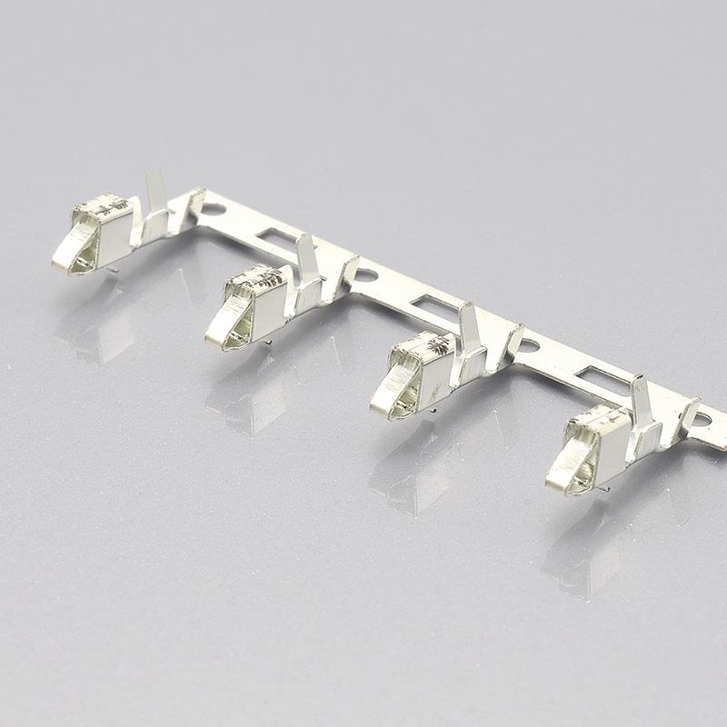
KONNRA KR2507 2.50mm pitch female terminal, the socket contact side
Environmental and Durability Programme
PS-KR2507-01 §7 publishes nine environmental and durability tests, each with a stated requirement.
| Clause | Test | Condition | Requirement |
|---|---|---|---|
| §7.1 | Durability | Mated up to 30 cycles at 10 cycles per minute, EIA-364-09C | Contact resistance 20mΩ max |
| §7.2 | Temperature rise | Carrying rated current load, EIA-364-70B | Temperature rise 30℃ max |
| §7.3 | Vibration | Amplitude 1.5mm P-P; sweep 10~55~10 Hz in 1 minute; 2 hours in each X, Y and Z axis, EIA-364-28B | Contact resistance 20mΩ max; discontinuity 1 microsecond max |
| §7.4 | Shock | 490 m/s² (50g), 3 strokes in each X, Y and Z axis, EIA-364-27B | Contact resistance 20mΩ max; discontinuity 1 microsecond max |
| §7.5 | Heat resistance | 105 ±2℃ for 96 hours, EIA-364-17B | Contact resistance 20mΩ max |
| §7.6 | Cold resistance | −40 ±2℃ for 96 hours, EIA-364-59 | Contact resistance 20mΩ max |
| §7.7 | Humidity | 40 ±2℃, 90–95% RH, 96 hours, EIA-364-31B | Contact resistance 40mΩ max; dielectric strength must meet §5.3; insulation resistance 100MΩ min |
| §7.8 | Thermal shock | 5 cycles of −40℃ for 30 min, room temperature 5 min, +105℃ for 30 min, room temperature 5 min, EIA-364-32B | Contact resistance 40mΩ max |
| §7.9 | Salt spray | 16 hours at 35 ±2℃ from a 5 ±1% solution, EIA-364-26B | Contact resistance 40mΩ max |
Four things are worth a designer’s attention.
The nine tests split into two contact-resistance tiers. Five of them — durability, vibration, shock, heat and cold — permit 20mΩ, which is exactly the post-conditioning limit JST publishes. Three — humidity, thermal shock and salt spray — permit 40mΩ. That split is worth understanding rather than averaging, because it means the two documents agree on the conditioning your product is most likely to see and diverge on the three that are hardest to survive. If your qualification plan includes salt spray or thermal shock, ask for measured values rather than comparing limits.
The conditioning levels are demanding. Heat at 105±2℃ for 96 hours, cold at −40±2℃ for 96 hours, thermal shock over five cycles between those two temperatures, and vibration for 2 hours in each of three axes with a 1 microsecond maximum discontinuity. Those are not nominal requirements, and they are the right ones to check when a connector goes into a vehicle, an outdoor enclosure or a panel on a machine.
Humidity is the only test that tightens the insulation-resistance requirement — §7.7 requires 100MΩ min, against the 500MΩ min JST publishes and the 500MΩ min the KR2507 specification sets in §5.2. That is a sensible allowance for absorbed moisture, and it is also the mechanism behind the change in insertion and withdrawal force that shows up on a humid production floor.
Salt spray runs for 16 hours, which is a moderate exposure. It is the test to revisit if the panel the connector mounts to is outdoors, on a vehicle underside, or in a wash-down area.
There Is No Soldering Section — and That Is Correct
PS-KR2507-01 has no soldering profile at all. Its §9.0 is not a temperature curve; it is a one-line remark about specification revisions.
That is the right document for this product, and it is worth explaining why, because a cross-reference reviewer trained on board connectors will read the omission as an error.
| What a wire-to-wire specification should contain | Present in PS-KR2507-01? |
|---|---|
| Housing material and finish | ✅ |
| Terminal material and finish | ✅ |
| Wafer / header material and finish | “N/A” — stated, not omitted |
| Solder tab | “N/A” — stated, not omitted |
| SMT reflow profile | Absent — correct |
| Wave soldering profile | Absent — correct |
| Solderability and solder-heat-resistance tests | Absent — correct |
| Crimp specification | ✅ §6.4 |
| Panel-mounting provisions | ✅ described |
Nothing is soldered in a wire-to-wire connection. The two halves are crimped to their cables and then mated to each other, so there is no solder joint, no board and no thermal profile to publish. A specification that carried a reflow curve for this part would be telling you the document had been adapted from a board connector rather than written for this one.
And the specification goes one better than simply omitting the sections. It states the omissions — the wafer and solder-tab rows are present and filled with “N/A”. That is a stronger form of correctness than deleting them, because it tells a reviewer that the question was asked and answered rather than overlooked.
The one comparison that cannot be made. JST publishes no soldering data for the SM either, for the same reason. So on this product there is nothing to reconcile, and no gap to close — which is the only round in this series where that is true of the soldering section.
Panel Mounting: the Feature With No Counterpart in the Board Families
This is what makes the SM pattern different from every other 2.5mm family in KONNRA’s range, and it is a genuine capability rather than a datasheet line.
JST publishes the panel cut-out dimensions for the SM, and it publishes them across three panel-thickness bands:
| Panel thickness band | JST publishes hole dimensions for it |
|---|---|
| 0.5mm to 0.9mm | ✅ |
| 1.0mm to 1.5mm | ✅ |
| 1.5mm to 2.0mm | ✅ |
JST also states an applicable panel thickness of 0.5mm to 2.0mm, and gives three operating notes that matter in production:
1. Punch holes in the panel according to the sketch and table shown above. Burrs must be removed. 2. The strength of the panel must be considered when punching two or more holes. 3. The connector must be inserted from the same side as the hole is punched.
Those three notes are the difference between a panel-mount connector that works and one that does not. Burrs change the effective hole size and can prevent the housing from seating. A panel with several holes punched loses strength between them, which changes how it behaves under a cable pull. And punching direction determines which face has the burr — so a connector inserted from the wrong side is fighting the sheet rather than seating in it.
What the KR2507 documentation says, and what it does not.
| Attribute | JST SM | KONNRA KR2507 |
|---|---|---|
| Applicable panel thickness | 0.5mm to 2.0mm | Not published as a figure; the product page says the connectors “offer excellent ease of installation on a wide range of panel thicknesses without the need for any tools or fasteners” |
| Panel cut-out dimensions | ✅ Published, in three thickness bands | Not published |
| Burr / punch-direction / panel-strength notes | ✅ Published | Not published |
| Tool-free mounting | Implied by the design | Stated explicitly |
So the capability is present on both sides but the engineering data is only on one. If you are cutting a panel for this connector, the cut-out drawing is the document you need, and it is a document to request from us rather than infer from the product page. Ask for the panel cut-out drawing for your panel thickness at the same time as the quote — it is a two-line request and it prevents a first-article failure that no amount of connector inspection will find.
What the Component Pages Say
All four KR2507 component pages carry the same feature block, and — unusually for this series — they agree with each other and with the specification on every row.
| Feature | Value on all four component pages |
|---|---|
| Product Type / Category | Wire to Wire |
| Assembly Type | Housing (two pages) / Terminal (two pages) |
| Pitch | 2.50mm |
| Product Series | KR2507 Series |
| Compatible | SM Series |
| Operating Voltage (AC/DC) | 250V |
| Current | 3A (3A Max on the terminal pages) |
| Contact Resistance | 10mΩ Max |
| Insulation Resistance | 500MΩ Min |
| Number of Rows | 1 |
| Number of Positions | 2P~16P |
| Colour | Black |
| Material | PA66 UL94 V-2 |
| Wire/Cable Size (AWG) | 22#-28# |
| Insulation Diameter (terminal pages only) | 1.6mm Max |
| Operating Temperature Range | -40℃~105℃ |
| Industry Standard — UL | E482542 |
Every row matches the specification. Compatible: SM Series appears on all four, with one wording — which is not something every series in this range manages. The contact resistance, insulation resistance, voltage, current, material, colour, wire size and temperature rows are consistent across the specification, the product page’s General Specification block and all four component pages.
That consistency is worth naming, because it is the reason this guide spends its length on the parts rather than on the paperwork. The three findings that matter here — the V-2 flammability rating, the 1.6mm insulation ceiling, and the missing panel data — are all real properties of the product or honest gaps, not errors in the documents.
And one small warning about the component page URLs. The four components live at /components/2507-hg/, /2507-hm/, /2507-tg/ and /2507-tm/. hg is the Male Housing and hm is the Female Housing — so the second letter does not follow the obvious “male/female” order, and the same is true of tg and tm for the terminals. Order from the words on the page, not from the URL.
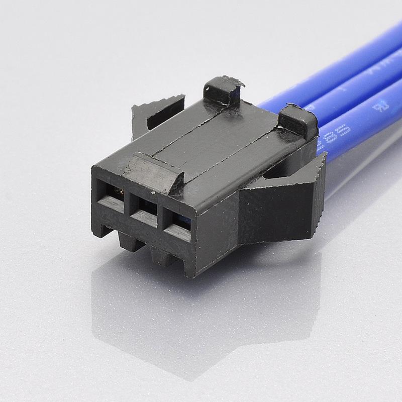
KONNRA KR2507 male housing, 2.50mm pitch wire-to-wire, panel mountable
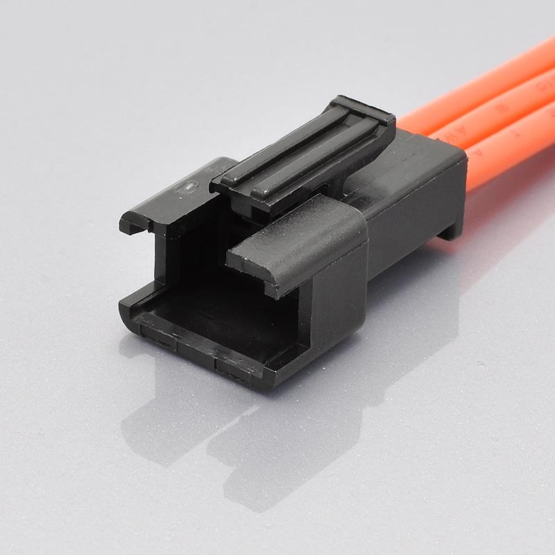
KONNRA KR2507 female housing, the receptacle side of the SM 2.5 pattern
Full series documentation
- KR2507 series engineering drawing (PDF)
- KR2507 product specification
PS-KR2507-01(PDF) - KR2507 package specification (PDF)
- Male housing product drawing · Female housing product drawing
- Male terminal product drawing · Female terminal product drawing
➡️ Request the panel cut-out drawing and the drawings for your circuit count
The Product Page Describes a Different Product
This section points at our own page, because a reviewer will notice it and it is better answered here than discovered later.
The KR2507 is a wire-to-wire connector with no board-side component. Three passages in its product-page Advantages text describe something else:
| Passage on the KR2507 page | What it describes |
|---|---|
| “…which ensures that the wires are securely fastened and removed from the board.” | A board-mount connector |
| “…the connector can be easily removed from the board without the need to hold the wires.” | A board-mount connector |
| “The use of a fully sealed header shroud design is particularly suitable for working environments with high humidity.” | A sealed connector with a header shroud — neither of which a wire-to-wire part has |
| “…without having to rely on the complex mechanism design of ZIF sockets.” | A zero-insertion-force board socket |
None of those four statements describes this product. The KR2507 has no board to be removed from, no header and no shroud, and it is not a ZIF socket. They read as prose carried over from a board-mount, sealed connector, and the “fully sealed” claim in particular is the kind of line a customer will quote back when they discover the part is not sealed.
What is actually true, and what the page should say, is in the rest of its own text and in the specification:
- High contact pressure from the contact geometry, with a positive latch — the page’s first advantage, and correct
- A friction lock plus a locking mechanism holding the two housings together — the “safety locking mechanism” line, and correct
- Tool-free panel mounting across a range of panel thicknesses — correct, and the most useful thing on the page
- The contacts are individually surrounded by housing walls — the short description line, and correct
- Crimp terminations with published crimp geometry — correct, and covered by §6.4
So the fix is a wording correction rather than a product change. If you are evaluating the KR2507 from that page, work from the specification and from the panel-mounting statements; the board and sealing language in the Advantages block is a documentation defect on our side, and it is on our correction list.
The 2.5mm Family: Where the KR2507 Sits
Four KONNRA 2.5mm cross-references now exist, and the KR2507 is the only wire-to-wire one. This table is the fastest way to see why the choice is structural rather than electrical.
| Attribute | KR2507 — JST SM | KR2504 — JST EH | KR2501 — JST XH | KR2502 — Yeonho 2.5 |
|---|---|---|---|---|
| Type | Wire-to-wire | Wire-to-board | Wire-to-board | Wire-to-board |
| Wafer / header | None | DIP only | DIP and SMT | DIP and SMT |
| Panel mounting | Yes | No | No | No |
| Soldering | None | Wave only | Wave and reflow | Wave and reflow |
| Withstanding voltage | 1,500 VAC | 800 VAC | 1,000 VAC | 1,000 VAC |
| Insulation resistance | 500MΩ | 1,000MΩ | 1,000MΩ | 1,000MΩ |
| Contact resistance (initial) | 10mΩ | 20mΩ | 20mΩ | 20mΩ |
| Current / voltage | 3A / 250V | 3A / 250V | 3A / 250V | 3A / 250V |
| Wire range (original) | AWG #28–#22 | AWG #32–#22 | AWG #30–#22 | AWG #22–#28 |
| Wire range (KONNRA) | 22#–28# | 22#–24# | 22#–28# | 22#–28# |
| Insulation O.D. (KONNRA) | 1.6mm Max | 1.9mm Max | 1.2–1.8mm | 1.2–1.8mm |
| Circuits (original / KONNRA) | 2–12 and 18 / 2–16 | 2–15 / 2–16 | 1–16 and 20 / 2–16 | 2–15–16 / 2–20 |
| Housing flammability | PA66 V-2 | PA66 V-0 | PA66 V-0 | PA66 V-0 |
| Unit price driver | Just the parts and the wire — no board, no soldering | Plus a wafer and a solder operation | Plus a wafer and a solder operation | Plus a wafer and a solder operation |
Three readings of that table.
The KR2507 is the odd one out architecturally, and that is its value. Nothing is soldered, so a connection is two crimped cable ends and a latch. In a serviceable inline joint — a light fitting, a sensor drop, a panel port — that removes a process step and a failure mode at the same time.
Its electrical position is genuinely different, not better or worse. The 1,500V withstand is the highest in the family and the 500MΩ insulation resistance and 10mΩ contact resistance are the most demanding figures in the family — because those are JST’s SM figures, and the KR2507 matched them instead of falling back on the house numbers. On this product the tighter limits are inherited from the original, which is the strongest form of cross-reference.
And the one row where it is weaker is the one to act on. The housing flammability rating is PA66 V-2 where every other series in the table is V-0, and where JST specifies the SM at V-0. That is the difference this guide leads with, and it is a question for us rather than an assumption for the drawing.
Where the KR2507 is the clear choice:
- The connection is cable to cable — no PCB involved
- The connection has to pass through a panel, and the panel cut-out is available or can be cut
- The joint has to be serviceable in the field without a soldering iron
- High dielectric withstand matters — 1,500V is the highest in the family
- A tight contact-resistance budget matters — 10mΩ initial is the lowest in the family
Where a board family is the answer: the cable has to land on a PCB at all. And if a UL94 V-0 housing is a requirement, resolve that question with us before going further — it is the one row in the table that is not simply a specification difference.
➡️ JST EH 2.5 Connector Complete Guide (KR2504) · JST XH 2.5 Connector Complete Guide (KR2501) · Yeonho YH 2.5 Connector Complete Guide (KR2502) · Explore the full 2.5mm pitch range · Wire-to-wire connector range
Documentation and Change Control
PS-KR2507-01 is a 6-page document — one page shorter than the neighbouring specifications in this range — Edition A1, carrying the same date in its “Date Issued” and “Date Revised” fields — 2022/2/26 — and no revision history table. Its §9.0 reads, in full:
“Any change or revision for the product specification will not be announced in advance. Please contact our sales representative for the latest information.”
The signature block reads “Written: Arvin · Checked: / · Approved: Min xinhao”, with the checking field left empty.
Why six pages rather than seven is worth a sentence. The missing page is the soldering section that a board connector needs and this one does not — so the shorter document is the more accurate one. A specification that is one page shorter because it omits a section the product does not have is evidence of authoring, not of abridgement.
The product drawings are per-component, and there are four of them, which is more than most series in this range publish: a male housing drawing, a female housing drawing, a male terminal drawing and a female terminal drawing, in addition to the series drawing. That matters more here than elsewhere, because the four KR2507 components are not interchangeable and a series-level drawing cannot tell you the difference between the male and female housing.
Against that, here is what the original publishes for the SM:
- The series catalogue, with the housing part numbers and their A and B dimensions for 2 to 12 and 18 circuits, and the quantities per bag
- Contact specifications per part number —
SYM-001T-P0.6andSHF-001T-0.8BS— with their applicable wire ranges, insulation O.D. window and reel quantities - Panel cut-out dimensions across three panel-thickness bands, plus the burr, panel-strength and insertion-direction notes
- Crimp machine and applicator identifications per contact — the machine, the applicators and the dies
- Recognized E60389 and the TÜV reference R50120150, with RoHS2 compliance stated
- Handling precautions for terminals and connectors, referenced from the catalogue
Two practical consequences.
Quote the revision, not just the series. §9.0’s wording says you will not be told when the document changes, which is common in this industry and is exactly the reason to pin what you designed to. If your qualification file cites the KR2507, cite PS-KR2507-01 Edition A1 and the section number, and ask for written confirmation that it is still current at the point you release.
Request the four component drawings, not only the series drawing. The male and female housings and the male and female terminals are four different parts, and the series drawing does not resolve which is which.
Applications Where the SM Pattern Is Used
The SM’s combination — 2.5mm pitch, 3A, 250V, panel-mountable, crimp-terminated, nothing soldered — puts it in a specific place in a design: the connection you make when there is no board to land on, or when the board should not have to be opened to change a cable.
| Application | Why the SM pattern fits |
|---|---|
| LED lighting and strip feeds | The classic inline joint between a driver, a strip and a run of cable — and the pattern the LED trade reached for by default |
| Panel-mounted ports and bulkhead connections | The one feature the board families in this range do not have: a cable exit through a cut-out, mounted without tools |
| Sensor and actuator drops | An inline, field-serviceable joint where a board connector would mean opening the enclosure |
| Battery and power leads | 3A at 250V with a positive latch, on a cable-to-cable joint that can be re-made |
| Signage and display wiring | Many small current circuits run in a chain, joined inline rather than landed on a board |
| Appliance and equipment internal harnesses | Cable-to-cable joins where a crimped, latched connection is easier to build and to repair than a soldered one |
| Instrumentation and test leads | Field-replaceable connections that a technician can make without a soldering iron |
The honest limits are current, the wire, and the housing rating. 3A per contact is the ceiling at this pitch. The wire range is AWG #28 to #22 — and on the KR2507 the insulation window is 1.6mm Max with no published floor, so a heavy-walled wire at 22 AWG needs checking against the terminal rather than assuming. And the housing is documented at PA66 UL94 V-2, which is the one row to raise with us if your requirement set names a flammability grade.
Cable assembly options
KONNRA builds cable assemblies on the KR2507 system — and for a wire-to-wire family the options are different from a board connector’s, because both ends are cable:
| Cable type | Description | Typical use |
|---|---|---|
| Single-ended | One housing on one end, bare wire leads on the other | A pigtail that lands in a terminal block or a chassis loom |
| Double-ended, male-to-female | The mating pair on one cable — a complete inline joint | Extending a run, or a serviceable link in a harness |
| Male-to-female extension | One male and one female housing, made to a length | Off-the-shelf extension leads for LED and sensor runs |
| Panel drop | One housing panel-mounted, the other free | A cable exit through an enclosure wall |
| Adapter and transition cables | KR2507 on one end, another series or family on the other | Interfacing an SM-pattern run to a board connector, a terminal block or a different brand |
The adapter case is worth calling out for this family specifically. Because the SM is wire-to-wire and the neighbouring 2.5mm KONNRA series are wire-to-board, the most common requirement is a cable that starts as a crimp inline joint and ends as a board connector — SM-pattern to JST XH, SM-pattern to JST PH, or SM-pattern to 2.54mm. Those are harnesses to order, and they are more common than a substitution in this family, because there is no cross-reference that turns a wire-to-wire original into a board part.
Connector lead time is typically 2–3 weeks; wiring harness lead time is typically 3–4 weeks.
➡️ Explore KONNRA wiring harness capabilities
Sourcing: What Procurement Teams Ask
Engineering decides that a connector will work. Procurement decides whether the supply chain around it is safe — and for this family there are two questions specific to it.
“Our drawing says SMP or SMR or SYM — can you supply it?” Yes. Send the full JST part number and we will map it to the KR2507 for your circuit count, and tell you in writing what differs. Note that the SM’s contact naming is inverted from expectation — the plug housing SMP- takes the socket contact SHF-001T-0.8BS, and the receptacle housing SMR- takes the pin contact SYM-001T-P0.6. If your drawing names a housing and a contact, quote both.
“Can you be a second source without changing our design?” On the electrical sheet, yes — and this is the strongest case of the 2.5mm cross-references. Five figures match exactly: the 1,500V withstand, the 500MΩ insulation resistance, the 10mΩ initial contact resistance, the AWG #28–#22 wire range, and the 3A / 250V ratings. Three things need answering rather than assuming, and we will put each in writing: the housing flammability rating (V-2 against JST’s V-0), the 1.6mm insulation ceiling with no published floor, and the panel cut-out dimensions.
“What are your lead times?” Connector production lead time is typically 2–3 weeks; wiring harness lead time is typically 3–4 weeks. Key materials are prestocked to shorten cycles.
“How long for samples?” Complete connector set samples can be delivered within 45 days. For a wire-to-wire family, note that a “complete set” is four parts — two housings and two terminals — plus the cable, so a sample request should say whether you want loose components or a made-up assembly.
“What qualifications do you hold?” KONNRA holds ISO9001, ISO14001, IATF16949, ISO45001:2018 and ISO13485 among its quality systems, together with UL product and operational safety certification — the KR2507 components carry UL file E482542. Note that JST lists Recognized E60389, the TÜV reference R50120150 and RoHS2 compliance for the SM. RoHS is a document request rather than a redesign; raise it at enquiry stage along with any flammability-grade requirement.
“Are you a manufacturer or a trader?” A manufacturer. Dongguan Konnra Electronics Co., Ltd., founded 2004, with in-house mould design, injection moulding, stamping, assembly and inspection — which is why the housing pair, the terminal pair and the cable assembly can come from one quality system.
“Is the connector sealed?” No. Our own product page uses the phrase “fully sealed electrical interface” in its advantages text, and that sentence does not describe this product — the KR2507 is a wire-to-wire connector with no header and no shroud. If your application needs an IP-rated or sealed connection, say so at enquiry stage; it is a different family, not a different option on this one.
How to Get a Cross-Reference Check on Your Part Number
Send us:
- The full JST part number, if you have it — a housing (
SMP-04V-B,SMR-04V-N,SMP-18V-BC) and a contact (SYM-001T-P0.6for the pin side,SHF-001T-0.8BSfor the socket side). Quote both the housing and the contact, and note the inverted pairing - Which side is which — which housing goes on which cable, and whether you are holding the plug or the receptacle
- Circuit count — and note that the KR2507 is documented 2 to 16 while JST catalogues 2 to 12 and 18
- Wire specification — AWG size and insulation outside diameter measured. The wire range matches the original, but the insulation window does not, and it has no published floor
- Whether the connection is panel-mounted, and the panel thickness. The cut-out dimensions differ by thickness band, and we will need to send you the drawing for yours
- Any flammability requirement — if your specification names UL94 V-0 for the housing, raise it here
- Application and annual volume, so configuration, tooling and packaging can be matched
- A drawing or a photograph, if the part number is unreadable
- Whether you need a made-up cable assembly rather than loose components
What you get back: a mapped KONNRA part number with the relevant drawings including the panel cut-out, a specification comparison against your original part including the insulation window, written answers on the flammability rating and the panel dimensions, and a sample and quote plan.
Engineer’s Pre-Release Checklist
Run this before you release a drawing for a JST SM 2.5 pattern connector.
- Confirm the connection is wire-to-wire. This family has no wafer and no board landing. If the design needs a PCB connection, it is a different family.
- Housing flammability rating resolved. The KR2507 is documented at PA66 UL94 V-2; JST specifies PA 6 at UL94V-0. If a V-0 housing is required, put the question to us in writing.
- Insulation outside diameter measured, not assumed, and checked against the 1.6mm Max ceiling. The window has no published floor, against JST’s 1.2mm.
- Wire gauge checked against the 22#–28# range — this one matches the original exactly, so a gauge check is a confirmation rather than a risk.
- Contact resistance budgeted at 10mΩ initial and 20mΩ after conditioning — and note that three of the nine environmental tests permit 40mΩ, not 20mΩ.
- Panel thickness and cut-out drawing requested. JST publishes cut-outs for 0.5–0.9mm, 1.0–1.5mm and 1.5–2.0mm panels; ours is a drawing request.
- Burr, panel-strength and insertion-direction notes carried into the build instruction — punch direction determines which face has the burr, and the connector must be inserted from the punched side.
- Temperature requirement checked. Above +85℃, ask for the heat-ageing evidence rather than inheriting the documented −40℃ to +105℃.
- Circuit count checked at both ends. Documented 2 to 16; JST catalogues 2 to 12 and 18. There is no 18-way, and JST derates its 18-way to 2A.
- Current rating at your circuit count confirmed if you are near 3A at 14 ways or more.
- Male and female parts ordered by the words, not the URL suffix.
hgis the Male Housing andhmis the Female Housing;tgandtmfollow the same non-obvious order. - The contact ordered to match the housing. The plug housing takes the socket contact; the receptacle housing takes the pin contact.
- Stripping length set to 2.1–2.6mm — the longest in the 2.5mm family, so a setup sheet carried over from another series will be wrong.
- Crimp applicator data requested with the quote if you crimp in house. The pin and socket contacts need different dies.
- Lock and retention understood. Terminal-to-housing retention is 1.5 kgf (14.7 N) minimum — lower than the board families’ 2.0 kgf — while the two housings are held by the arm lock and, when panel-mounted, by the panel.
- Nothing on the page’s “fully sealed” line relied upon. The KR2507 is not a sealed connector; raise an IP requirement at enquiry.
- Whether a made-up cable assembly is wanted, since both ends of this connection are cable.
➡️ Send us your drawing. We will review it against the KR2507 specification and come back with any mismatch we find — before you commit tooling. Submit a drawing for review
Frequently Asked Questions
What is a JST SM 2.5 connector?
A 2.5mm pitch, crimp-style, disconnectable wire-to-wire connector with high contact pressure, an arm lock mechanism and panel-mount capability. JST rates it 3A and 250V AC/DC, over −25℃ to +85℃, with a 1,500 VAC/minute withstanding voltage, 500MΩ minimum insulation resistance, 10mΩ maximum initial contact resistance, and an applicable wire range of AWG #28 to #22 (0.08–0.33mm²). JST catalogues it in 2 to 12 and 18 circuits, and adds that any circuit count “can be used either panel mounted or free hanging.”
What is the KONNRA equivalent of the JST SM 2.5 connector?
The KONNRA KR2507 series — a 2.50mm pitch wire-to-wire connector offered as a male housing, a female housing, a male terminal and a female terminal. Housing H2507M***0401C (pin side) and H2507F***0401C (socket side); terminals T2507MPT0101C and T2507FPT0101C. There is no wafer, and the specification says so explicitly rather than leaving the row blank. All four component pages carry Compatible: SM Series.
Is the KR2507 a drop-in replacement for the JST SM 2.5?
On the electrical sheet, it is the closest cross-reference in the 2.5mm family. Five figures match exactly: the 1,500 VAC withstanding voltage, the 500MΩ insulation resistance, the 10mΩ initial contact resistance, the AWG #28–#22 wire range, and the 3A / 250V ratings. Three things need confirming rather than assuming: the housing is documented at PA66 UL94 V-2 where JST specifies UL94V-0; the insulation window is 1.6mm Max with no published floor against JST’s 1.2–1.8mm; and the panel cut-out dimensions are not published by us. Ask about all three in writing.
Is the housing UL94 V-0 or V-2?
The KR2507 is documented at PA66 UL94 V-2 — in the specification’s material section and on all four component pages. JST specifies the SM housing as PA 6 at UL94V-0. The difference between the two ratings is the cotton-indicator test: a V-2 material may shed burning particles that ignite a cotton pad below the specimen; a V-0 material may not. V-2 is the weaker rating. If your requirement set names V-0, raise it with us at enquiry stage.
What wire gauge does the JST SM 2.5 connector use?
AWG #28 to #22 (0.08mm² to 0.33mm²), with an insulation outside diameter of 1.2mm to 1.8mm, on both the pin contact SYM-001T-P0.6 and the socket contact SHF-001T-0.8BS. The KONNRA KR2507 documents the same conductor range — 22# to 28# — but a narrower insulation window of 1.6mm Max, with no lower bound published. So a wire at the top of its insulation tolerance is inside the original’s specification and outside ours.
What is the contact resistance of the JST SM?
10mΩ maximum initially, and 20mΩ maximum after environmental tests — JST publishes both figures in its SM catalogue. The KR2507 specification matches the initial figure at 10mΩ Max (§5.1), and matches the post-conditioning figure at 20mΩ for the five environmental tests up to §7.6 — durability, vibration, shock, heat and cold. Three tests permit 40mΩ instead: humidity (§7.7), thermal shock (§7.8) and salt spray (§7.9). If your qualification includes one of those three, ask for measured values rather than comparing limits.
What is the withstanding voltage of the JST SM?
1,500 VAC per minute — the highest in this pitch family, and one and a half times the 1,000 VAC of the JST XH and the 800 VAC of the JST EH. The KONNRA KR2507 matches it: the specification’s §5.3 requires 1500V AC for 1 minute between adjacent terminals or to ground (EIA-364-20A), and the product page states 1500V AC/ minute. This is the strongest single agreement in the comparison.
What is the insulation resistance of the JST SM?
500MΩ minimum, measured by applying 500V DC for one minute (EIA-364-21B). The KR2507 matches it at 500MΩ Min. Note that this is half the 1,000MΩ that the neighbouring KONNRA 2.5mm series publish — so the KR2507 matched the original rather than falling back on the house figure. Under humidity (§7.7) the requirement relaxes to 100MΩ min on both sides.
Is the JST SM the same as the JST XH?
No, and the difference is structural. Both are 2.5mm pitch, 3A and 250V — but the SM is wire-to-wire (two crimped cable housings that mate with each other, with panel-mounting capability and no PCB involvement) and the XH is wire-to-board (one cable housing that mates with a wafer soldered to a board). They do not mate with each other, and no cross-reference turns one into the other. The KONNRA equivalents are KR2507 for the SM and KR2501 for the XH. Where a build needs both, the answer is an adapter harness.
Does the JST SM mount to a panel?
Yes, and it is the feature the neighbouring 2.5mm families do not have. JST publishes the panel cut-out dimensions in three panel-thickness bands — 0.5–0.9mm, 1.0–1.5mm and 1.5–2.0mm — with an applicable panel thickness of 0.5mm to 2.0mm, and three operating notes: burrs must be removed, the strength of the panel must be considered when punching two or more holes, and the connector must be inserted from the same side as the hole is punched. The KR2507 is panel-mountable too — its page describes tool-free mounting across a wide range of panel thicknesses — but we do not publish the cut-out dimensions, so ask us for the drawing for your panel thickness.
How many circuits does the JST SM come in?
2 to 12, and 18. JST’s housings run from SMP-02V / SMR-02V to SMP-12V / SMR-12V, plus SMP-18V / SMR-18V. JST also derates the 18-circuit version to 2A, against 3A for 2 to 12 circuits. The KONNRA KR2507 documents 2 to 16, continuous — so it covers 13 to 16, which JST’s housing list does not, and does not cover 18.
Which JST contact goes with which housing?
The pairing is inverted from what the names suggest, and this is the most common ordering mistake in this family:
| Housing | Contact |
|---|---|
Plug housing SMP-… |
Socket contact SHF-001T-0.8BS |
Receptacle housing SMR-… |
Pin contact SYM-001T-P0.6 |
Both contacts are phosphor bronze, tin-plated with a reflow treatment, and both are supplied on reels — 8,500 for the pin contact and 5,000 for the socket contact. The two contacts also need different crimp dies, so a shop tooling the family for the first time should request both applicator references.
Is the JST SM connector sealed or waterproof?
No. It is a wire-to-wire crimp connector with an arm lock and panel-mounting provisions; JST does not claim a sealing rating for it, and neither do we. If you see “fully sealed electrical interface” in our product page’s advantages text, that sentence does not describe this product — it is wording carried over from a different family, and we have flagged it for correction. If your application needs an IP-rated connection, say so at enquiry stage; that is a different family rather than an option on this one.
What is the difference between the 2507 hg, hm, tg and tm components?
They are the four parts of the wire-to-wire set, and the suffix letters do not follow the obvious male/female order: hg is the Male Housing and hm is the Female Housing; tg is the Male Terminal and tm is the Female Terminal. Order from the words on the component page, not from the two letters in the URL.
How do I identify which 2.5mm connector I actually have?
Measure the pitch first — 2.50mm is this class, 2.54mm is Molex KK or “DuPont”, 2.00mm is JST PH. Then ask one structural question that settles it faster than any dimension: is there a board involved? If the connector mates two cables, or passes through a panel cut-out, it is the SM pattern — and the KONNRA equivalent is the KR2507. If it mates a cable to a wafer soldered on a PCB, it is a board family — EH, XH or Yeonho 2.5, covered by the KR2504, KR2501 and KR2502. Because four families now sit at 2.50mm with the same 3A/250V headline ratings, the pitch alone tells you almost nothing. If the part number is unreadable, photograph the connector next to a ruler and send it to us.
How long does it take to get samples?
KONNRA can deliver complete connector set samples within 45 days. For this family a complete set is four parts — two housings and two terminals. Connector production lead time is typically 2–3 weeks and wiring harness lead time typically 3–4 weeks.
Start Your Cross-Reference Check
KONNRA supplies the KR2507 series as individual components or as complete pre-crimped cable assemblies, with customisation available for application-specific requirements.
- Request a quote — KR2507 pricing, MOQ and configuration options for your circuit count
- Request a sample — complete connector set samples within 45 days, loose parts or made-up
- Request cross-reference verification — confirm KR2507-to-JST-SM equivalence against your specific part number and wire
- Request a written answer on the housing flammability rating — if your requirement set names UL94 V-0, this is the question to ask first
- Request the panel cut-out drawing for your panel thickness
- Request the performance evidence — measured contact resistance after humidity, thermal shock and salt spray, where the documented allowance is 40mΩ rather than the original’s 20mΩ
- Request drawings — the series drawing and the four component drawings (male and female housing, male and female terminal)
- Request the crimp applicator data — if you crimp in house, for both the pin and the socket contact
- Request a vendor qualification pack — certificates, test capability summary, RoHS and quality documentation
- Request adapter and transition cable assemblies — SM pattern to JST XH, to JST PH, to 2.54mm, or to a terminal block
- Submit a drawing for review — we will flag any specification mismatch before you commit tooling
Contact KONNRA Electronics
- Phone: (86)-769-85449875
- Email: info@konnra.com
- Address: No.6 Nanchang South Road, Chijiao, Wangniudun, Dongguan, Guangdong, China
- Contact us
Sources and method. Every figure in this guide is taken from a manufacturer document, and where two manufacturers — or two documents from the same manufacturer — disagree, the difference is stated rather than averaged. JST SM figures are taken from JST’s published SM connector catalogue: the family description (“2.5 mm pitch / Disconnectable Crimp style wire-to-wire connectors” and “The SM series are 2.5 mm pitch, wire-to-wire connectors that perform reliably in high-density, small current applications”), the four feature lines (high contact pressure; highly reliable housing construction; mountable on a variety of panels; arm lock mechanism), the current rating (3A AC/DC max.), voltage rating (250V AC/DC max.), temperature range (−25 to +85℃, stated as including temperature rise in applying electrical current), contact resistance (initial value 10mΩ max.; after environmental tests 20mΩ max.), insulation resistance (500MΩ min.), withstanding voltage (1,500 VAC/minute), applicable wire (AWG #28 to #22, 0.08–0.33mm²), applicable panel thickness (0.5 to 2.0mm), the panel cut-out table across the three thickness bands with its three operating notes, RoHS2 compliance, the Recognized E60389 and TÜV R50120150 standards, the housing and contact part numbers (SMP-…V-B(N)C plug housings and SMR-…V-B / -N receptacle housings from 2 to 12 and 18 circuits; SYM-001T-P0.6 pin contact and SHF-001T-0.8BS socket contact, with insulation O.D. 1.2–1.8mm and reel quantities of 8,500 and 5,000), the housing material (PA 6, UL94V-0), the colour list (black; white/natural), the per-circuit current ratings (3A for 2–12 circuits; 2A for 18 circuits), the crimp machine and applicator identifications (AP-K2N; MK/SYM-001-06 and MKS-L with dies APLMK SYM001-06; MK/SHF-001-08S and APLMK SHF001-08S), the note that SM connectors of any circuit count can be used “either panel mounted or free hanging”, and the handling-precautions reference. JST XH, JST EH and Yeonho 2.5 figures in the family comparison are from JST’s published XH and EH pages and catalogues and from Yeonho Electronics’ own specification sheets, as set out in full in the linked guides. KONNRA KR2507 figures are from PS-KR2507-01 (Edition A1, dated 2022/2/26, 6 pages) sections 2.0, 3.0, 4.0, 5.1–5.3, 6.1–6.4, 7.1–7.9, 8.0 and 9.0, and from the KR2507 product page and the four KR2507 component pages. Three limitations are stated openly. First, JST does not publish a series-level insertion-and-withdrawal force table, an environmental test programme or a solder-resistance programme for the SM, so the KR2507’s figures in those areas are checked against themselves — all 45 entries of the section 8.0 force table reproduce from three arithmetic expressions — rather than reconciled against the original. Second, JST’s contact-level applicable-wire figures are published per contact, and both SM contacts share the same stated window, so no per-contact split is claimed here. Third, the panel cut-out dimensions for the KR2507 are not published on our side, and the guide states that as a gap to be closed by a drawing request rather than implying the data exists. The UL 94 rating distinctions in the flammability section are stated as the standard’s own test criteria; where they matter to your approval route, confirm the requirement with us in writing, and if a figure here disagrees with the current revision of a manufacturer document, the manufacturer document is right.