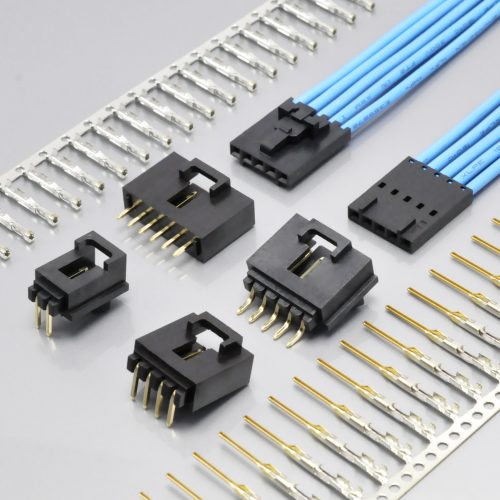
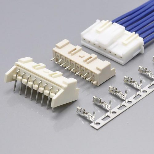
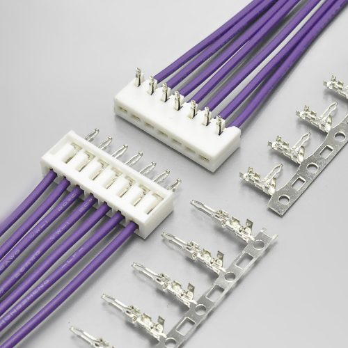
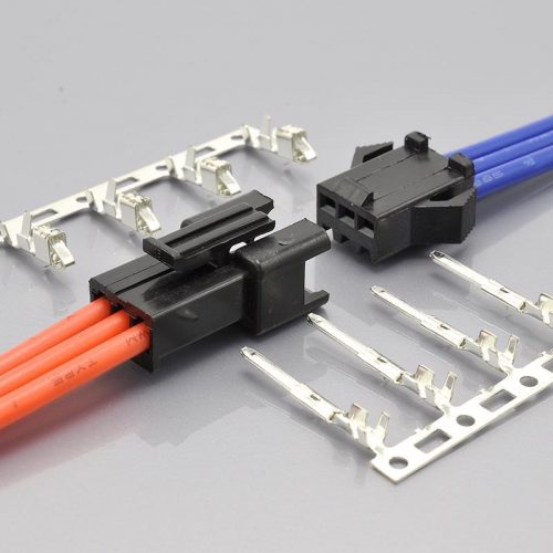
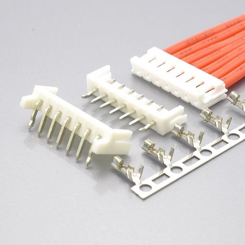
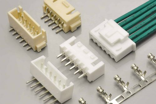
Quick answer: JST PH is a 2.00mm pitch wire-to-board crimp connector with a boxed, shrouded header, a mounting height of 8mm and a width of only 4.5mm in the top-entry version. It is rated 2A AC/DC at AWG #24 and 100V AC/DC, over −40°C to +105°C, with 800V AC for one minute of withstanding voltage and 1,000MΩ minimum insulation resistance. It accepts AWG #32 to #24 wire. The KONNRA KR2001 is the cross-reference equivalent, and on the headline electrical specification it is the closest match we have documented on any series: 100V, 2A, 20mΩ contact resistance, 1,000MΩ insulation resistance and 800V AC/minute all match JST exactly. The place where it stops matching is the wire: the KR2001’s published range is AWG #24–28, which does not cover AWG #30 or #32 — and its own product page says otherwise.
That last sentence is the most useful thing on this page, so it is worth unpacking before anything else.
JST reaches AWG #32 on this series by publishing three contacts: one for the fine wire, one for the standard range, and a third low-insertion-force variant of the standard range. The KR2001 publishes one terminal, covering AWG #24 to #28. So the cross-reference covers most of the PH range but not all of it, and the boundary is not obvious from a specification table because the parameters that match so well sit right next to the one that does not.
This guide sets out both manufacturers’ published data, states exactly where they agree and where they do not, and flags the two places where KONNRA’s own web page contradicts its own engineering documents. Every figure below is traceable to a source listed in the final section. Where a number is not published anywhere we could verify, we say so rather than filling the gap.
At a glance — JST PH vs the KONNRA KR2001
| Parameter | JST PH | KONNRA KR2001 | Status |
|---|---|---|---|
| Pitch | 2.0mm | 2.00mm | Match |
| Circuits | 2 to 16 | 2 to 16 | Match |
| Header style | Boxed, shrouded, top entry and side entry | SMT and DIP wafers, straight and right angle | Match in kind |
| Mounting height | 8mm | not stated | — |
| Top-entry width | 4.5mm | not stated | — |
| Rated voltage | 100V AC/DC | 100V AC/DC | Match |
| Rated current | 2A AC/DC (AWG #24) | 2A (24AWG) AC/DC | Match |
| Temperature range | −40°C to +105°C | −40°C to +105°C (PS, drawing and page table) | Match |
| Contact resistance | 20mΩ max | 20mΩ max | Match |
| Insulation resistance | 1,000MΩ min | 1,000MΩ min | Match |
| Withstanding voltage | 800V AC / 1 minute | 800V AC / minute | Match |
| Applicable wire | AWG #32 to #24 | AWG #24 to #28 | Differs |
| Insulation O.D. | φ0.5–1.5mm (two windows) | 1.5mm max | Differs in detail |
| Applicable PCB thickness | 0.8–1.6mm | not stated | — |
| Durability | see note | 30 cycles | — |
| Contact material | Copper alloy, tin-plated | Phosphor bronze / brass, tin or gold over nickel | Differs in finish |
| Housing material | PA, natural (white) | PA66, UL94 V-0 | Close |
| Clinched-post option | Yes (K suffix) |
Yes (01 = no K, 02 = with K) | Match |
| Gold plating | “Contact JST for gold-plated products” | Orderable (T01 / B01 / G03 / S00 codes) | KONNRA more explicit |
| Page-vs-spec consistency | — | Two contradictions on the KR2001 page | See below |
| Product page count | — | Two identical pages published | See below |

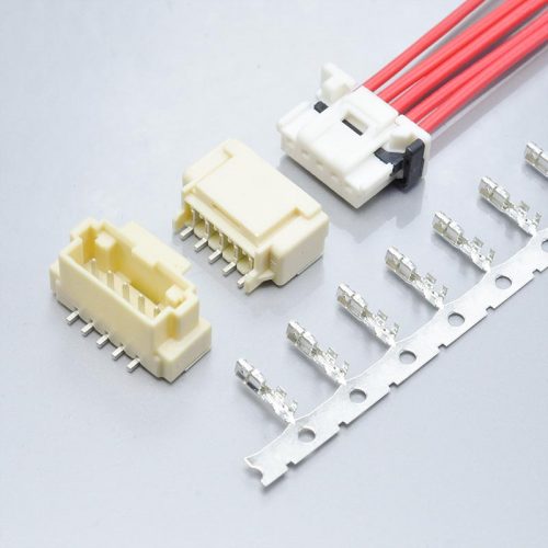
KR2001 — KONNRA’s JST PH 2.0 equivalent
A note on the durability row. JST’s PH datasheet as published does not state a mating-cycle figure in the general specification set; KONNRA’s KR2001 specifies 30 cycles. We are not going to guess at JST’s number, and the row is left as “see note” rather than filled with a figure from somewhere else. It is one of the items in the final checklist.
The five parameters that match, and why that matters more than usual
Most cross-reference guides spend their length on the differences. This one starts with the agreements, because on this series the agreements are unusually comprehensive and they are what makes the differences worth managing rather than disqualifying.
Voltage: 100V AC/DC on both. Molex, JST and KONNRA all publish rated voltage as a working voltage rather than a proof voltage, so this is a like-for-like comparison and it holds.
Current: 2A AC/DC at AWG #24 on both. JST writes “Current rating: 2 A AC/DC (AWG #24)”. KONNRA writes “Rated Current (Max.) 2A(24AWG) AC/DC” in §4.0 of the product specification. The same figure, at the same qualified wire gauge, with the same qualifier.
Temperature: −40°C to +105°C on both. JST’s PH is rated “−40°C to +105°C (including temperature rise in applying electrical current)”. KONNRA’s product specification, engineering drawing and web specification table all state −40°C to +105°C. This is a genuine match — and it is worth noting how different this series is from others in the same catalogue, where we have documented the cross-reference part claiming a range the original does not publish.
Contact resistance: 20mΩ max on both. JST specifies 20mΩ max after test; KONNRA specifies 20mΩ max measured by dry circuit at 20mV / 100mA to EIA-364-23C. Same figure, same order of magnitude of method.
Insulation resistance: 1,000MΩ min on both, measured at 500V DC for one minute per EIA-364-21B on the KONNRA side.
And the one that surprised us: withstanding voltage. JST specifies 800V AC for one minute with “no breakdown or flashover”. KONNRA specifies 800V AC for one minute with “no breakdown and flashover”. That is a full agreement on a parameter that is genuinely hard to match — and it is the opposite of what we found on other 2.00mm series, where the cross-reference part published a proof voltage 60% higher than the original’s. Here the two documents agree exactly.
Why this matters commercially. A cross-reference part is only worth the paperwork if the paperwork is short. On this series the electrical core needs almost no qualifying — five parameters, five matches, all at the same qualified conditions. That leaves the wire range as the single substantive engineering question, which is a much better position to be in than a list of a dozen divergences.
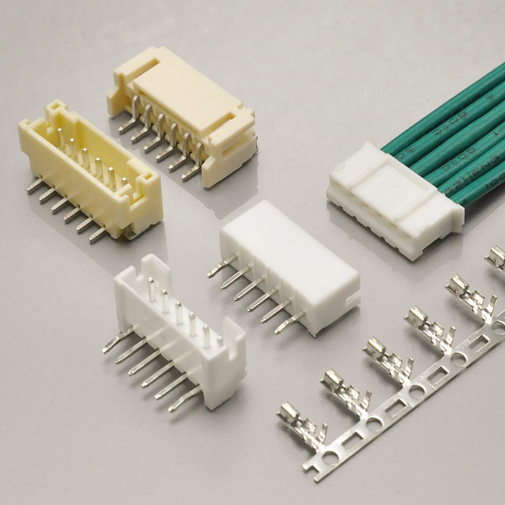
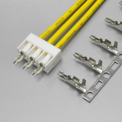
KR2001 crimp connector
The wire range is where the cross-reference stops
This is the one difference on this series that can change a bill of materials, and it is easy to miss because it lives in a four-character range rather than in a headline rating.
JST reaches its full wire range using three separate contacts:
| JST contact | Conductor size | Insulation O.D. | Qty/reel |
|---|---|---|---|
SPH-004T-P0.5S |
AWG #32 to #28 (0.032–0.08 mm²) | 0.5 to 0.9mm | 10,000 |
SPH-002T-P0.5S |
AWG #30 to #24 (0.05–0.22 mm²) | 0.8 to 1.5mm | 8,000 |
SPH-002T-P0.5L |
AWG #28 to #24 (0.08–0.22 mm²) | 0.8 to 1.5mm | — |
KONNRA publishes one terminal for the KR2001:
Applicable wires: AWG 24# ~ 28#, Insulation O.D. 1.50 mm MAX
Both the product specification §4.0 and the terminal drawing give the same range. Lay the two against each other:
| Gauge | JST PH | KONNRA KR2001 |
|---|---|---|
| AWG #32 | ✅ SPH-004T-P0.5S |
❌ not covered |
| AWG #30 | ✅ SPH-002T-P0.5S |
❌ not covered |
| AWG #28 | ✅ SPH-002T-P0.5S / -L |
✅ covered |
| AWG #26 | ✅ SPH-002T-P0.5S / -L |
✅ covered |
| AWG #24 | ✅ SPH-002T-P0.5S / -L |
✅ covered |
So AWG #30 and AWG #32 are outside the KR2001’s published range, even though they are inside JST’s. If your harness uses fine wire — and PH is very commonly used on small signal and sensor runs where #30 and #32 are normal — that gap matters. It is not a limitation the datasheet shouts about, because the range is stated correctly and simply; it only becomes visible when you compare it against what the original covers.
And this is where KONNRA’s own web page gets it wrong. The KR2001 product page’s Overview section states:
“It supports a current of 2A and a voltage of 100V, is suitable for AWG#24 to AWG#32 wires…”
AWG #24 to #32 is not the same as AWG #24 to #28. The page claims support for AWG #30 and #32, and neither the product specification nor the terminal drawing supports that claim. A buyer who reads only the page would believe the KR2001 covers the full PH wire range. It does not.
What to do: specify against the product specification, PS-KR2001-01, which states AWG #24–28. If you need AWG #30 or #32, ask us directly — do not assume, and do not rely on the Overview paragraph.
The insulation diameter window has the same shape of gap
JST publishes insulation diameters as windows, one per contact:
SPH-004T-P0.5Saccepts 0.5 to 0.9mmSPH-002T-P0.5Sand-Laccept 0.8 to 1.5mm
KONNRA publishes a single figure for the whole series: 1.5mm maximum.
So a wire with 0.6mm insulation is inside JST’s fine-wire window and has no published equivalent in the KR2001’s range — which is consistent with the KR2001 not covering AWG #32, since thin-wall fine wire is exactly where those sub-0.8mm diameters come from.
And the practical rule either way is the same one that applies to every crimp connector. The insulation crimp height is set against the insulation diameter. Molex, JST and KONNRA all publish crimp heights per wire gauge and none of them can publish one for a wire diameter outside the range the tool was set for. Measure your wire’s insulation rather than reading the diameter off a catalogue, and compare the measurement against the window that applies to the contact you intend to buy.
The second page-vs-spec contradiction: temperature
The KR2001 product page carries the temperature range in two places, and they do not agree.
Place one — the “General Specifaction” table on the page:
Temperature Range: −40℃~+105℃
Place two — the Overview paragraph on the same page:
“…and can operate stably over a temperature range of −25°C to +85°C.”
And the controlled documents:
| Source | Temperature range |
|---|---|
| KR2001 product specification PS-KR2001-01 §4.0 | −40°C ~ +105°C |
| KR2001 engineering drawing (housing, terminal and all wafer drawings) | −40°C ~ +105°C |
| KR2001 product page — General Specification table | −40℃ ~ +105℃ |
| KR2001 product page — Overview prose | −25°C to +85°C |
| JST PH datasheet | −40°C to +105°C |
Four sources say −40°C to +105°C, including JST’s own datasheet. One source — a paragraph of marketing prose on KONNRA’s page — says −25°C to +85°C.
The controlled figure is −40°C to +105°C, and it matches the original exactly. The Overview paragraph is wrong, and it is wrong in the conservative direction: it understates the part’s capability by 15°C at the cold end and 20°C at the hot end.
Why this is worth flagging even though the error is “safe.” A page that understates a rating is not dangerous to a designer, but it is dangerous to a qualification workflow. If a customer’s engineering team copies the Overview text into a supplier qualification file, they will document a part that is worse than the specification says it is — and a future audit comparing the qualification file against the datasheet will find a discrepancy that nobody can explain. Worse, the −25°C to +85°C wording is the kind of figure that looks plausible enough to pass review.
Action: cite PS-KR2001-01 §4.0. It says −40°C to +105°C, and it agrees with JST.
And note what KONNRA’s numbers rest on. The claim is not free-floating — the same specification publishes the tests behind it:
| Test | Condition | Requirement |
|---|---|---|
| Heat resistance (§7.5) | 105 ± 2°C, 96 hours (EIA-364-17B) | No damage; contact resistance 40mΩ max |
| Cold resistance (§7.6) | −40 ± 2°C, 96 hours (EIA-364-59) | No damage; contact resistance 40mΩ max |
| Thermal shock (§7.8) | −40°C 30 min → room temp 5 min → +105°C 30 min → room temp 5 min = 1 cycle, 5 cycles (EIA-364-32B) | No damage; contact resistance 40mΩ max |
The rated extremes are the tested extremes, held for 96 hours each and cycled five times between them. That is the right way round.
The force table: one rule, and a fixed 0.20 kgf loss that hits small connectors hardest
KONNRA publishes a complete insertion and withdrawal force table for the KR2001 across the full 2-to-16 circuit range, both as new and after the rated 30 cycles. JST’s PH datasheet as published does not carry an equivalent table, so there is nothing to compare it against on the original side — which makes the table worth reading on its own terms, as a complete published specification.
| Circuits | Insertion force (max) | Withdrawal force (min), initial | Withdrawal force (min), after 30 cycles |
|---|---|---|---|
| 2 | 2.5 | 0.50 | 0.30 |
| 3 | 3.0 | 0.60 | 0.40 |
| 4 | 3.5 | 0.70 | 0.50 |
| 5 | 4.0 | 0.80 | 0.60 |
| 6 | 4.5 | 0.90 | 0.70 |
| 7 | 5.0 | 1.00 | 0.80 |
| 8 | 5.5 | 1.10 | 0.90 |
| 9 | 6.0 | 1.20 | 1.00 |
| 10 | 6.5 | 1.30 | 1.10 |
| 11 | 7.0 | 1.40 | 1.20 |
| 12 | 7.5 | 1.50 | 1.30 |
| 13 | 8.0 | 1.60 | 1.40 |
| 14 | 8.5 | 1.70 | 1.50 |
| 15 | 9.0 | 1.80 | 1.60 |
| 16 | 9.5 | 1.90 | 1.70 |
(All values in kgf. 1 kgf = 9.8N.)
The rules behind the table
Read the columns as sequences rather than as values, and the specification collapses into two extremely simple statements:
Insertion force rises by exactly 0.50 kgf per circuit — 2.5, 3.0, 3.5 … 9.5. There is no kink and no exception across the whole 2-to-16 range. In closed form, insertion force (max) = 1.5 + 0.5 × (circuits).
Withdrawal force rises by exactly 0.10 kgf per circuit — 0.50, 0.60, 0.70 … 1.90. Also no exception. Withdrawal force (min) = 0.30 + 0.10 × (circuits).
Those two rules are worth carrying into a design review, because they let you sanity-check any quoted figure. A KR2001 insertion force that is not 0.5 kgf per circuit, or a withdrawal force that is not 0.1 kgf per circuit, does not fit the specification as published.
The finding that matters: the retention loss is a fixed 0.20 kgf
Now compare the last two columns. At every one of the fifteen position counts in the table, the post-30-cycle withdrawal force is exactly 0.20 kgf lower than the initial value.
- 2 circuits: 0.50 → 0.30
- 6 circuits: 0.90 → 0.70
- 11 circuits: 1.40 → 1.20
- 16 circuits: 1.90 → 1.70
Not approximately. Exactly, at all thirty data points.
That means the retention lost over the rated life is a fixed absolute amount rather than a proportional one — so the relative loss depends entirely on how many positions you have:
| Circuits | Initial withdrawal | After 30 cycles | Retention lost |
|---|---|---|---|
| 2 | 0.50 kgf | 0.30 kgf | −40.0% |
| 4 | 0.70 kgf | 0.50 kgf | −28.6% |
| 6 | 0.90 kgf | 0.70 kgf | −22.2% |
| 8 | 1.10 kgf | 0.90 kgf | −18.2% |
| 10 | 1.30 kgf | 1.10 kgf | −15.4% |
| 16 | 1.90 kgf | 1.70 kgf | −10.5% |
A 2-circuit KR2001 loses 40% of its withdrawal force across the rated 30 cycles. A 16-circuit part loses 10.5%. The absolute loss is identical in both cases — 0.20 kgf — but the small connector has far less retention to begin with, and 0.30 kgf is a modest figure to be relying on.
This is worth taking seriously precisely because small connectors get specified casually. A 2-position PH connector on a short battery or sensor lead feels like a trivial part. But if that lead is handled during assembly, dressed inside a housing, or flexed in service, the retention margin at cycle 30 is 40% smaller than the number on the front of the datasheet — and the datasheet number was already the minimum for a brand-new part.
How this compares across the catalogue, for calibration. We documented a different 2.00mm series whose cross-reference part publishes the same shape of table with a fixed 0.10 kgf loss, which works out to a 21.7% loss at 2 positions. The KR2001’s specification is stricter in absolute terms — it declares a larger fixed loss — and correspondingly more demanding to design against. The methodology is identical; the numbers are not, which is exactly why the numbers are worth reading rather than assuming.
What to do with it. For low-position-count designs, treat the initial withdrawal figure as a beginning-of-life number. If the connector will be mated more than a handful of times, specify against the 30th-cycle column, and note that KONNRA’s §7.1 durability test is the test that establishes both columns: 30 cycles at a rate not exceeding 10 per minute, with contact resistance required to stay at or below 40mΩ afterwards — double the 20mΩ initial limit.

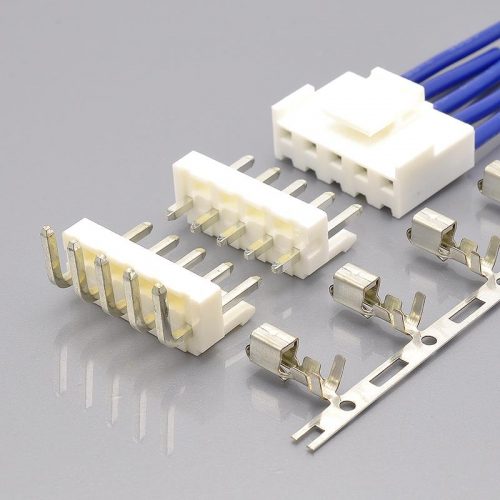
KR2001 terminal — shared across the 2-to-16 circuit range
What the JST PH connector is, mechanically
JST describes the series in its own datasheet as a “low-profile wire-to board connector” with “a mounting height of 8 mm and a width of only 4.5 mm in the top-entry version”, at a 2.0mm pitch, and says it is “suitable for a wide range of applications, including use in high-density PCBs where space in electronic equipment is limited.” It lists “Boxed-shaped shrouded header” and “Space-saving design” among its features.
Four consequences follow from that description, and each one affects a design decision.
The 8mm mounting height is the trade this series makes. On a 2.00mm pitch, an 8mm mated height is tall — noticeably taller than the low-profile families in the same pitch class. What you get for the height is a boxed shroud, and the shroud is doing real work: it encloses the posts, guides the housing onto the header, and protects the contact field from handling damage. If your enclosure is height-constrained, 8mm is the number to check first, and it is the parameter most likely to eliminate PH before anything electrical does.
The 4.5mm top-entry width is unusually narrow relative to the pitch. That narrowness is what makes the series suitable for dense boards, and it comes from the shroud sitting around the posts rather than beside them.
It comes in both through-hole and SMT. JST publishes a through-hole range (top entry B2B-PH-K-S through B16B-PH-K-S, side entry S2B-PH-K-S through S16B-PH-K-S) and a separate SMT range (top entry B2B-PH-SM4-TB through B16B-PH-SM4-TB, side entry S2B-PH-SM4-TB through S15B-PH-SM4-TB). Note where that SMT list stops: the side-entry SMT range ends at 15 circuits, while every other range reaches 16. The KR2001 mirrors the two mounting styles with DIP and SMT wafers in both straight and right-angle versions.
The through-hole headers come with clinched posts, and the part number says so. JST’s naming puts a K in the through-hole header part numbers — B2B-PH-K-S — where the model-number allocation documents “Clinched (Kinked)” as the assembly style. That matters mechanically: a clinched post is deformed against the underside of the board and resists the connector working out of the holes before soldering. KONNRA’s KR2001 publishes the same option as two separate DIP wafer part numbers, C2001RD***01T0101PB and C2001RD***01T0102PB, which the drawings label “No K” and “Have K” respectively. The option therefore exists on both sides, expressed differently: a letter in JST’s part number, a single digit in KONNRA’s.
And the SMT side carries reinforcements. JST’s SMT header material list includes “Reinforcement: Copper alloy, tin-plated” alongside the post and housing, and offers “Top-entry headers with suction tape” — both of which exist because SMT headers experience pick-and-place forces that through-hole parts do not. KONNRA’s SMT wafer drawings similarly list a solder nail in brass, tin-plated over nickel. On the DIP side, by contrast, KONNRA’s specification states “Solder tab: None” — consistent with the clinched-post option being the DIP retention method instead.
Terminal selection: three contacts, one of which JST warns you about
Because the PH housing is a crimp housing, the terminal selection is where the electrical and mechanical design actually happens — and on this series JST offers three contacts with overlapping ranges.
| JST contact | Conductor size | Insulation O.D. | Qty/reel | Notes |
|---|---|---|---|---|
SPH-004T-P0.5S |
AWG #32 to #28 (0.032–0.08 mm²) | 0.5 to 0.9mm | 10,000 | Standard type |
SPH-002T-P0.5S |
AWG #30 to #24 (0.05–0.22 mm²) | 0.8 to 1.5mm | 8,000 | Standard type |
SPH-002T-P0.5L |
AWG #28 to #24 (0.08–0.22 mm²) | 0.8 to 1.5mm | — | Low insertion force type |
All three are documented as copper alloy, tin-plated, and JST’s contact note adds a line that matters for anyone specifying a plating: “Contact JST for gold-plated products.”
The low-insertion-force contact comes with three warnings
JST’s own note on SPH-002T-P0.5L is short, and every clause in it is a design instruction:
“SPH-002T-P0.5L is a low insertion force type contact for easier insertion/withdrawal operation. Please take the application and environment into consideration as the low insertion force type contact is less resistant to vibration. Please note that the crimp height is different from the standard PH contact. Please contact JST for further details.”
Unpack it.
It exists for easier insertion and withdrawal. That is the whole reason to choose it — if an operator is repeatedly mating a multi-position PH connector by hand, a lower insertion force is a real ergonomic and process benefit.
It is less resistant to vibration. JST states this outright, and does not quantify it. The implication is architectural rather than incidental: a contact that mates with less force holds with less force, and on a series whose standard withdrawal force is already being reduced across its rated life (see the force table above), choosing the low-force contact in a vibrating application is moving in the wrong direction. If your product is vibration-exposed, this is the contact to avoid unless you have test data for your specific assembly.
Its crimp height is different from the standard contact. This is the warning that costs money. SPH-002T-P0.5S and SPH-002T-P0.5L share an overlapping wire range — AWG #28 to #24 is common to both — but they do not share a crimp height. A production line running both contacts cannot share one applicator setup, and a crimp-height check written for one will reject good crimps from the other. JST’s tooling table reflects this by giving the -L contact its own applicator with dies.
The tooling
| Contact | Crimping machine | Applicator | Applicator with dies |
|---|---|---|---|
SPH-004T-P0.5S |
AP-K2N | MKS-L-10 | APLMK SPH004-05S |
SPH-002T-P0.5S |
— | MKS-L | APLMK SPH002-05S |
SPH-002T-P0.5L |
— | — | APLMK SPH002-05L |
JST notes: “Contact JST for fully automatic crimping applicator.”
The crimp specification on the KONNRA side
KONNRA publishes crimp dimensions and pull-strength requirements for its single KR2001 terminal, across the wire gauges it covers:
| Crimp parameter | 24 AWG | 26 AWG | 28 AWG |
|---|---|---|---|
| Crimp width (conductor, ①) | 1.30 ± 0.10 | 1.30 ± 0.10 | 1.30 ± 0.10 |
| Crimp height (conductor, ①) | 0.85 ± 0.05 | 0.75 ± 0.05 | 0.70 ± 0.05 |
| Crimp width (insulation, ②) | 1.60 ± 0.10 | 1.60 ± 0.10 | 1.60 ± 0.10 |
| Crimp height (insulation, ②) | 1.75 ± 0.10 | 1.65 ± 0.10 | 1.50 ± 0.10 |
| Crimp strength | 3.63 kgf min | 2.27 kgf min | 1.36 kgf min |
| Stripping length | 1.5–2.0mm | 1.5–2.0mm | 1.5–2.0mm |
| Terminal quantity | 10,000 pcs per reel |
Three observations.
The conductor crimp height window is ±0.05mm at every gauge, and it steps down by 0.10mm per wire size — 0.85, 0.75, 0.70. A 0.10mm wide window on a sub-millimetre target is a tight process, and it is why the applicator setup has to be verified by measurement rather than by eye.
The crimp width is the same at every gauge (1.30 ± 0.10 conductor, 1.60 ± 0.10 insulation), while the heights differ. That is normal — width is set by the terminal’s barrel geometry, height by the tool’s stroke — but it means a width measurement cannot tell you which gauge you are set up for. Measure the height.
Crimp strength falls by a factor of 2.7 across the range — 3.63 kgf at AWG #24 down to 1.36 kgf at #28. If your harness mixes gauges, the pull-test acceptance criterion differs per circuit and a single pass/fail figure will either pass bad crimps at 24 AWG or reject good ones at 28 AWG.
And one number worth noticing: the stripping length is 1.5–2.0mm. That is longer than on some comparable series, and it follows from the crimp geometry — a shorter strip will not fill the conductor barrel correctly on this terminal.
How to identify whether your connector is a JST PH
The 2.00mm pitch class is crowded — KONNRA’s own 2.00mm index lists more than fifteen series in this pitch — and PH is one of the most widely second-sourced connectors in the world, so identification questions come up constantly. Work through these in order.
1. Measure the pitch. 2.00mm on centres. That eliminates the 1.25mm, 1.50mm and 2.50mm families. Measure across at least four pitches and divide rather than measuring one gap.
2. Is the header boxed — a shroud around the posts? JST describes PH as a “Boxed-shaped shrouded header.” If you are looking at an open pin field, it is not PH. The box is the feature JST leads with, and it is visually the most obvious thing about the mated pair.
3. Measure the mated height. JST publishes a mounting height of 8mm and a top-entry width of 4.5mm. On a 2.00mm pitch, 8mm is tall; if your connector is noticeably lower-profile, you may be looking at a different family in the same pitch.
4. Look at the housing’s keying. The housing has a polarising feature that prevents it being inserted the wrong way round — KONNRA’s own description of the equivalent describes “the spacer design in the middle of the interface” which “can effectively prevent reverse power connection.” A housing with no keying at all in this pitch is a different series.
5. Check the post size. The PH header’s posts are square, nominally 0.5mm — which is what the P0.5 in JST’s contact part numbers refers to, and what KONNRA’s wafer drawing states as SQ 0.50 ± 0.05. A 0.64mm square post is a different 2.00mm family.
6. Read the part numbers. JST’s PH numbers are highly recognisable once you know the pattern:
| Function | Pattern | Example |
|---|---|---|
| Housing | PHR- + circuits |
PHR-4 |
| Through-hole header, top entry | B + circuits + B-PH-K-S |
B4B-PH-K-S |
| Through-hole header, side entry | S + circuits + B-PH-K-S |
S4B-PH-K-S |
| SMT header, top entry | B + circuits + B-PH-SM4-TB |
B4B-PH-SM4-TB |
| SMT header, side entry | S + circuits + B-PH-SM4-TB |
S4B-PH-SM4-TB |
| Contact | SPH- + type + T-P0.5 + suffix |
SPH-002T-P0.5S |
The B / S prefix on the header is the entry direction; the K is the clinched post; the SM4-TB marks the SMT version. KONNRA’s equivalents use H2001 for the housing, T20010 for the terminal and C2001 for the wafers.
7. Check the housing colour. JST publishes PH housings in natural (white) as standard, with a long list of optional colours documented in the model-number allocation — black, blue, orange, dark pink, fluorescent yellow, grey, lemon yellow, light blue, green, brown, purple, pink, red, tomato red and yellow. A coloured PH housing is a standard option rather than a custom part, which is worth knowing if you are trying to match an existing design.
8. And a warning about JST’s own documentation. The datasheet carries this note: “Specifications registered to overseas standards may differ from the general specifications listed above,” and on the board layout: “Hole dimensions differ depending on the type of PCB and PCB drilling method. When using PCB made of hard material composed of fiberglass cloth, please consider a larger hole diameter. The above dimensions are for reference only. Please contact JST for further details.”
If your product is certified to a standard, the certified specification may not be the one on the datasheet. That is worth knowing before you qualify a cross-reference against the datasheet.

KR2001 housing
Where JST PH sits in the 2.00mm class
KONNRA’s own 2.00mm index lists more than fifteen series in this pitch, spanning a 2.5× range in current and a 2.5× range in voltage. The table below uses KONNRA’s published cross-reference positioning, so the entries are the supplier’s own:
| KONNRA series | Cross-references to | Architecture | Current | Voltage | Circuits |
|---|---|---|---|---|---|
| KR2001 | JST PH 2.0 | Wire-to-board | 2A | 100V | 2–16 |
| KR2002 | IL-S | Wire-to-board | 2A | 100V | 2–16 |
| KR2004 | Yeonho YH200 PH 2.0 | Wire-to-board with lock | 2A | 250V | 2–16 |
| KR2003 | JST SAN / SJN 2.0 | Board-in | 2A | 250V | 2–16 |
| KR2005 | JST PHD 2.0 | Wire-to-board, 2 rows | 3A | 250V | 2*2–2*20 |
| KR2007 | Molex mx2.0 | Wire-to-wire | 2A | 125V | 2–16 |
| KR2009 | Hirose DF3 | Wire-to-board | 3A | 250V | 2–15 |
| KR2014 | JST PA 2.0 | Wire-to-board | 3A | 250V | 2–15 |
| KR2017 | Molex DuraClik mx2.0 | Wire-to-board | 3A | 125V | 2–14 |
| KR2022 | JST PAL 2.0 | Wire-to-board | 3A | 250V | 2–14 |
| KR2023 | JST ULH 2.0 | Wire-to-board, TPA | 5A | 100V | 2–10 |
Four observations worth carrying into a design review.
The 250V entries dominate this table, and the KR2001 is not one of them. It sits at 100V, alongside only the KR2002 and the KR2023. So the voltage rating is the parameter that separates PH from most of its 2.00mm neighbours — and if your requirement creeps above 100V, the replacement involves both a different series and a different footprint.
There are two “PH 2.0” entries in KONNRA’s catalogue, and they are not the same product. The KR2001 cross-references JST PH 2.0 at 100V. The KR2004 is described as “PH 2.0 Wire to Board Connector with Lock“ and cross-references Yeonho YH200 PH 2.0 at 250V. They share a “PH 2.0” label, a 2.00mm pitch, 2–16 circuits and a 2A rating, and they differ on the cross-referenced original, on voltage and on the lock. If you are sourcing a PH connector, confirm which of the two you are looking at before comparing anything else — this is exactly the kind of near-duplicate naming that produces a wrong part on a purchase order.
PH is at the low end of the class on current as well. At 2A it sits below the 3A block that most of this table occupies. As with every small connector, the rating is qualified by wire gauge, so the 2A belongs to AWG #24 — and on this series the smaller gauges in the family carry correspondingly less.
Only one entry in the class is board-in, and only one is wire-to-wire. The KR2003 (JST SAN/SJN, no wafer) and the KR2007 (Molex mx2.0, wire-to-wire) are the architectural outliers. If your requirement is “2.00mm, and it must be wire-to-wire”, PH is not a candidate at all — the architecture decides it before the ratings do.
The full electrical and environmental comparison
Everything both sides publish, side by side. Where a parameter is published by only one supplier, that is stated rather than left blank — and on this series the split is unusually clean.
Ratings
| Item | JST PH | KONNRA KR2001 | Status |
|---|---|---|---|
| Rated voltage | 100V AC/DC | 100V AC/DC | Match |
| Rated current | 2A AC/DC (AWG #24) | 2A (24AWG) AC/DC | Match |
| Temperature range | −40°C to +105°C (incl. temperature rise) | −40°C to +105°C | Match |
| Applicable wire | AWG #32 to #24 | AWG #24 to #28 | Differs |
| Insulation O.D. | φ0.5–1.5mm | 1.5mm max | Differs in detail |
| Applicable PCB thickness | 0.8–1.6mm | not stated | — |
| Mounting height / width | 8mm / 4.5mm (top entry) | not stated | — |
| Durability | not stated in the datasheet’s general specification | 30 cycles | KONNRA only |
Electrical performance
| Item | JST PH | KONNRA KR2001 | Status |
|---|---|---|---|
| Contact resistance | 20mΩ max, presented against an “After test” condition | 20mΩ max, initial, dry circuit 20mV / 100mA (EIA-364-23C) | Match on the figure |
| Insulation resistance | 1,000MΩ min | 1,000MΩ min (EIA-364-21B, 500V DC / 1 min) | Match |
| Withstanding voltage | 800V AC / 1 minute, no breakdown or flashover | 800V AC / 1 minute (EIA-364-20A), no breakdown or flashover | Match |
| Temperature rise | not published | 30°C max (EIA-364-70B) | KONNRA only |
| Contact resistance after environmental exposure | not published | 40mΩ max | KONNRA only |
Read the contact resistance row carefully, because it is the one place where an apparent match is not quite a like-for-like. JST’s datasheet pairs the 20mΩ max figure with an “After test” condition — that is, a value measured after the electrical and environmental test sequence rather than on a new part. KONNRA specifies 20mΩ max as the initial value, measured by dry circuit to EIA-364-23C, and separately publishes 40mΩ max as the post-environmental allowance.
So the two documents land on the same number from opposite directions: JST’s 20mΩ appears to be the end-of-test figure, and KONNRA’s 20mΩ is the beginning-of-life figure, with 40mΩ as its end-of-test figure. Both parts are within 20mΩ when new if JST’s initial value is lower, and both allow more after testing. But if your qualification document quotes “20mΩ max” as a single figure, state which condition you mean — and if you need JST’s initial value, it is a question for JST, because the datasheet reviewed here pairs the figure with the after-test condition.
Mechanical performance
| Item | JST PH | KONNRA KR2001 |
|---|---|---|
| Insertion / withdrawal force table | not published | published, 2–16 circuits (see above) |
| Terminal insertion force | not published | 0.5 kgf (4.9N) max |
| Terminal / housing retention | not published | 1.0 kgf (9.8N) min |
| Pin retention in the wafer | not published | 1.0 kgf (9.8N) min |
| Crimp pull strength | not published | 3.63 / 2.27 / 1.36 kgf min (24 / 26 / 28 AWG) |
| Post size | 0.5mm (implied by the P0.5 contact suffix) |
SQ 0.50 ± 0.05mm (wafer drawing) |
| Clinched post option | Yes (K in the part number) |
Yes (01 = no K, 02 = with K) |
| Board retention on the DIP wafer | clinched posts | solder tab: none |
Environmental performance
| Item | JST PH | KONNRA KR2001 |
|---|---|---|
| Durability | not published | 30 cycles, contact resistance ≤40mΩ after (EIA-364-09C) |
| Temperature rise | not published | 30°C max (EIA-364-70B) |
| Vibration | not published | 1.5mm P-P, 10→55→10 Hz in 1 min, 2 hours per axis, discontinuity ≤1 microsecond (EIA-364-28B) |
| Mechanical shock | not published | 490 m/s² (50g), 3 strokes in each of 6 directions (EIA-364-27B) |
| Heat resistance | not published | 105 ± 2°C, 96 hours (EIA-364-17B) |
| Cold resistance | not published | −40 ± 2°C, 96 hours (EIA-364-59) |
| Thermal shock | not published | 5 cycles (EIA-364-32B) |
| Humidity | not published | 40 ± 2°C, 90–95% RH, 96 hours (EIA-364-31B) → 40mΩ max, must meet the dielectric test, insulation resistance 100MΩ min |
| Salt spray | not published | 24 hours, 35 ± 2°C, 5 ± 1% NaCl (EIA-364-26B) |
| Solderability | not published | 245 ± 5°C, 3 ± 0.5 s, ≥95% of immersed area (EIA-364-52) |
| Solder heat resistance | not published | SMT profile §9.1 / DIP profile §9.2 |
The pattern here is the opposite of what you might expect from a cross-reference document. On this series, JST publishes the board-side geometry and the ratings, and KONNRA publishes the entire mechanical and environmental qualification programme. JST’s datasheet gives applicable PCB thickness, board layout tolerance, mounting height and width; KONNRA’s gives the vibration, shock, thermal, humidity and salt-spray requirements with their EIA standards cited, plus the force tables and the crimp specification.
Neither document is a superset of the other, and you need both. A complete qualification file for a KR2001 substitution should contain:
- From JST: the board layout and hole geometry, the applicable PCB thickness (0.8–1.6mm), the mounting height (8mm), and the approved overseas-standard specification if your product is certified.
- From KONNRA: the environmental test programme above, the insertion and withdrawal force table, the terminal and pin retention figures, and the crimp specification.
One caveat on the humidity line. KONNRA’s §7.7 requires 40mΩ max contact resistance, no dielectric breakdown, and 100MΩ minimum insulation resistance after 96 hours at 90–95% RH. That 100MΩ is a post-humidity allowance, not the part’s rating — which remains 1,000MΩ minimum under §5.2. Do not carry 100MΩ into a specification as the insulation resistance.
And one on the JST side that matters for certified products. The datasheet carries this note verbatim: “Specifications registered to overseas standards may differ from the general specifications listed above.” If your product is submitted under a UL, CSA or similar registration, the registered specification is the one that governs, and the datasheet figure you are comparing against may not be it.
Process and board layout
Board geometry
Three JST numbers decide whether a board can accept PH, and all three come from the datasheet:
- Applicable PC board thickness: 0.8mm to 1.6mm
- Tolerance for the PCB hole pitch: ±0.05mm, and it shall not accumulate
- The hole layout figure is “viewed from the connector mounting surface”
That last note is the one that causes rework. PH footprints are drawn from the connector mounting side, not from the solder side. Confirm the mirroring before you release a footprint, because getting it backwards produces a board that only fails once the connectors arrive.
JST then adds a caveat that is worth quoting in full:
“Hole dimensions differ depending on the type of PCB and PCB drilling method. When using PCB made of hard material composed of fiberglass cloth, please consider a larger hole diameter. The above dimensions are for reference only. Please contact JST for further details.”
The published hole dimensions are a guideline, not a specification, and the board material changes them — with fiberglass-cloth laminate specifically called out as needing a larger hole. If you are releasing a footprint for production, that is a conversation with the supplier rather than a dimension to copy from a PDF.
KONNRA publishes the matching figures on its wafer drawings: a recommended PCB layout total tolerance of ±0.05mm — the same as JST — and φ0.80mm plated holes with SQ 0.50 ± 0.05 posts. The layout tolerances agree; the hole and post sizes are consistent with JST’s layout.
Soldering
JST does not publish a soldering profile on the PH datasheet. KONNRA publishes both, in §9.0 of the product specification:
| SMT infrared reflow (§9.1) | Wave soldering (§9.2) | |
|---|---|---|
| Peak temperature | 255 (+5/−5)°C, 5–10 seconds | 250°C max, 3–5 seconds |
| Time at minimum 230°C / 217°C | 20–40 seconds at ≥230°C | 60–150 seconds at ≥217°C |
| Reflow zone | 90–120 seconds | 60–180 seconds |
| Pre-heat | 150–200°C | 150–180°C |
KONNRA adds the same note every serious supplier writes, and it is the note that matters most: “Please check welding conditions by your own devices beforehand. Because the condition changes by the soldering devices, P.C.boards, and so on.”
A published profile is a starting point, not a process. Run your own profile on your own board, particularly on a PH design where the header is small and sits close to the board surface.
Which wafer, and the retention question
KONNRA offers the KR2001 in four wafer styles — SMT straight, SMT right angle, DIP straight, DIP right angle — so the mounting and wire-exit decisions are independent of each other. And the DIP styles come with the clinched-post choice described earlier (C2001RD***01T0101PB for “No K”, C2001RD***01T0102PB for “Have K”).
Note the difference in how the two mounting styles hold themselves to the board. KONNRA’s specification lists a solder tab for the SMT wafer (brass, matte-tin plated over nickel) but states “Solder tab: None” for the DIP wafer. On the DIP side, the board retention therefore comes from the clinched posts — which is exactly the option JST writes into its own part number with the K. So:
- If your design needs the connector held before soldering, specify the
undefined(clinched) DIP wafer. - If your design relies on a solder nail or reinforcement tab, that exists on the SMT wafer, not the DIP one.
Choosing a “No K” DIP wafer on a design that assumed board retention is a silent mechanical downgrade — nothing in the electrical specification will catch it.
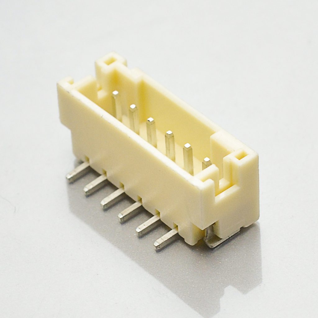
KR2001 SMT straight wafer
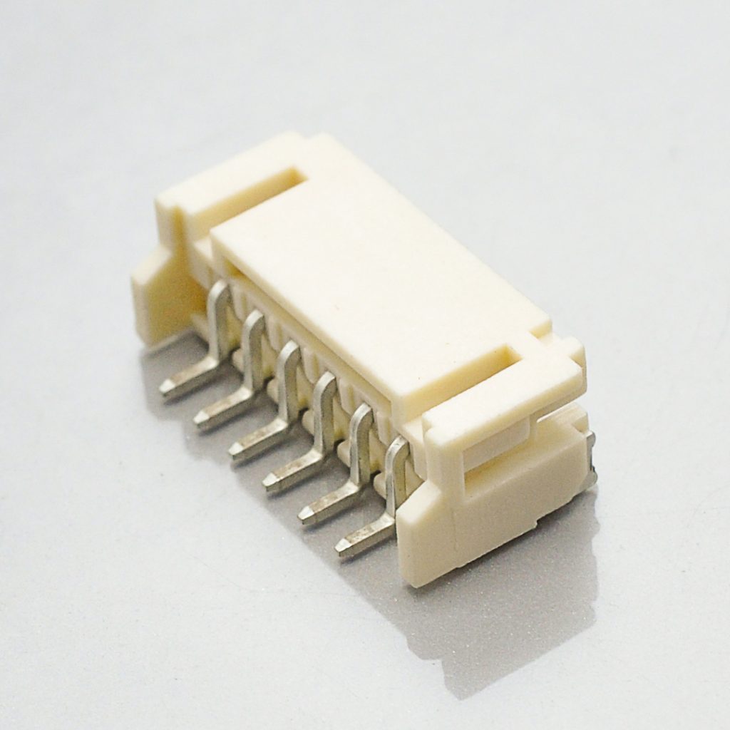
KR2001 SMT right-angle wafer
Wire routing, strain relief, and the retention question this series raises
There is no positive latch on PH. The housing engages the shrouded header and holds by friction, and the terminals hold in the housing by the lance engagement that the retention figures describe. That is a normal and perfectly serviceable arrangement — but on this series the published force table gives us a reason to be specific about it.
Start from the numbers. KONNRA’s table shows the KR2001’s withdrawal force falling by a fixed 0.20 kgf between the first cycle and the thirtieth, at every position count. That is:
- 0.50 kgf → 0.30 kgf on a 2-position connector (a 40% loss)
- 1.90 kgf → 1.70 kgf on a 16-position connector (a 10.5% loss)
0.30 kgf is 2.94N. That is the minimum force holding a mated 2-position KR2001 together at the end of its rated life. It is a real figure and the part is specified to it — but it is not much, and it is the number to design your harness against rather than the 0.50 kgf on the front of the table.
What follows from that, practically:
Anchor the harness close to the connector. A tie-down, clip or mounting point a short distance from the housing means that handling loads, vibration and thermal cycling are taken by the harness support rather than by the housing-to-header friction fit. This is standard practice on any small connector; on this series the published retention figures make it measurable rather than merely prudent.
Give the bundle a service loop rather than pulling it taut. A taut harness under a 2-position connector is a constant separating force. A loop is not.
Do not hang weight from the connector. On a battery lead or a sensor run, the wire gauge is small and the connector is small, and the temptation to use the harness as a handle during assembly is real. Note 22 of a comparable Molex specification puts it well: the cable assembly “should not have a constant stress or pulling force applied on it when it is in the mated condition.”
Remember what the vibration test proves and what it does not. KONNRA requires the KR2001 to hold continuity to within 1 microsecond through 2 hours per axis at 1.5mm peak-to-peak, and to 50g shock in six directions. That is a genuine electrical-continuity criterion under excitation — and it is a statement about a correctly supported connector. The test is the evidence that the design can hold; the strain relief is what makes it hold in your product.
And if retention is a primary requirement rather than a secondary one, there is a better answer than a strain-relief calculation. The PH architecture does not have a positive lock, and no amount of harness discipline changes that. If your specification calls for a locking connector, KONNRA’s own catalogue has a direct answer: the KR2004, described as “PH 2.0 Wire to Board Connector with Lock”, cross-referencing Yeonho YH200 PH 2.0, at the same 2.00mm pitch, the same 2-to-16 circuit range and the same 2A rating — but at a 250V voltage rating rather than 100V. If your application needs a lock and your voltage requirement is above 100V, that is the family to look at, and it is worth asking us to compare the two footprints before you commit either way.
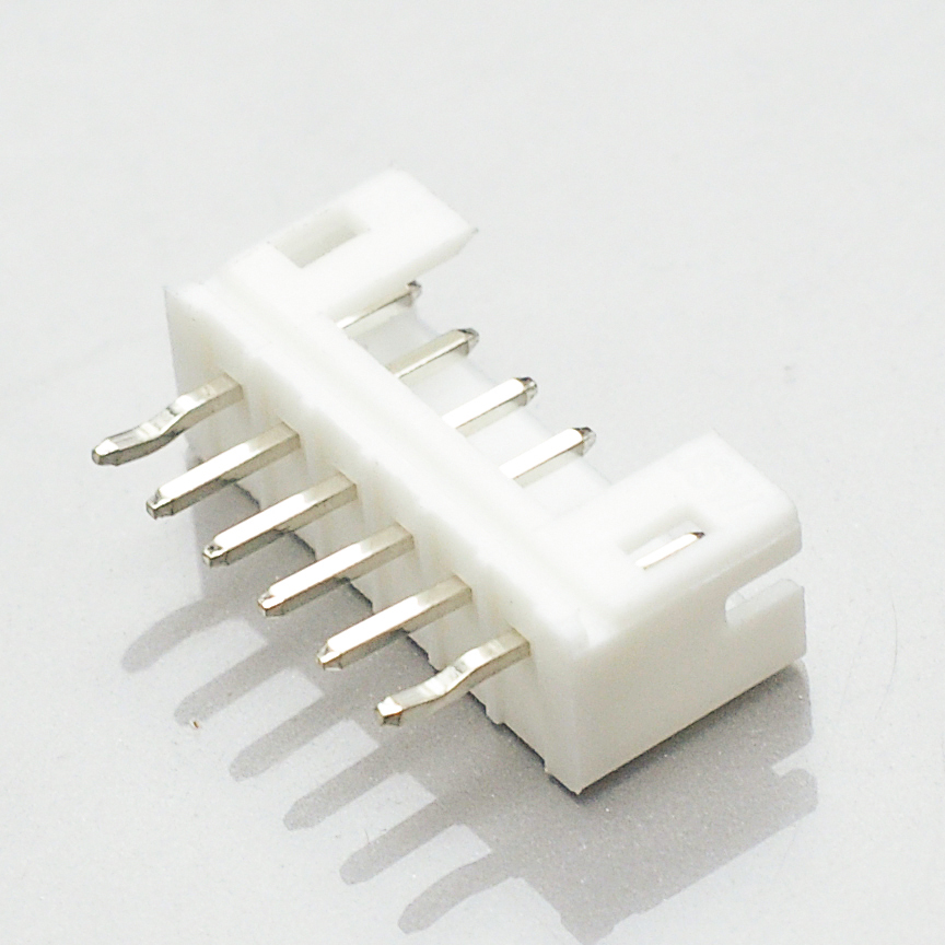
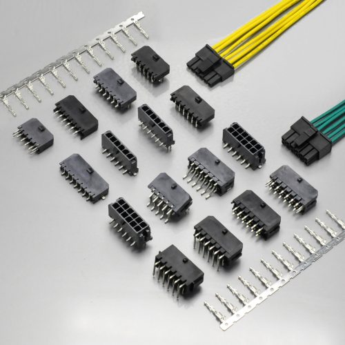
KR2001 DIP straight wafer
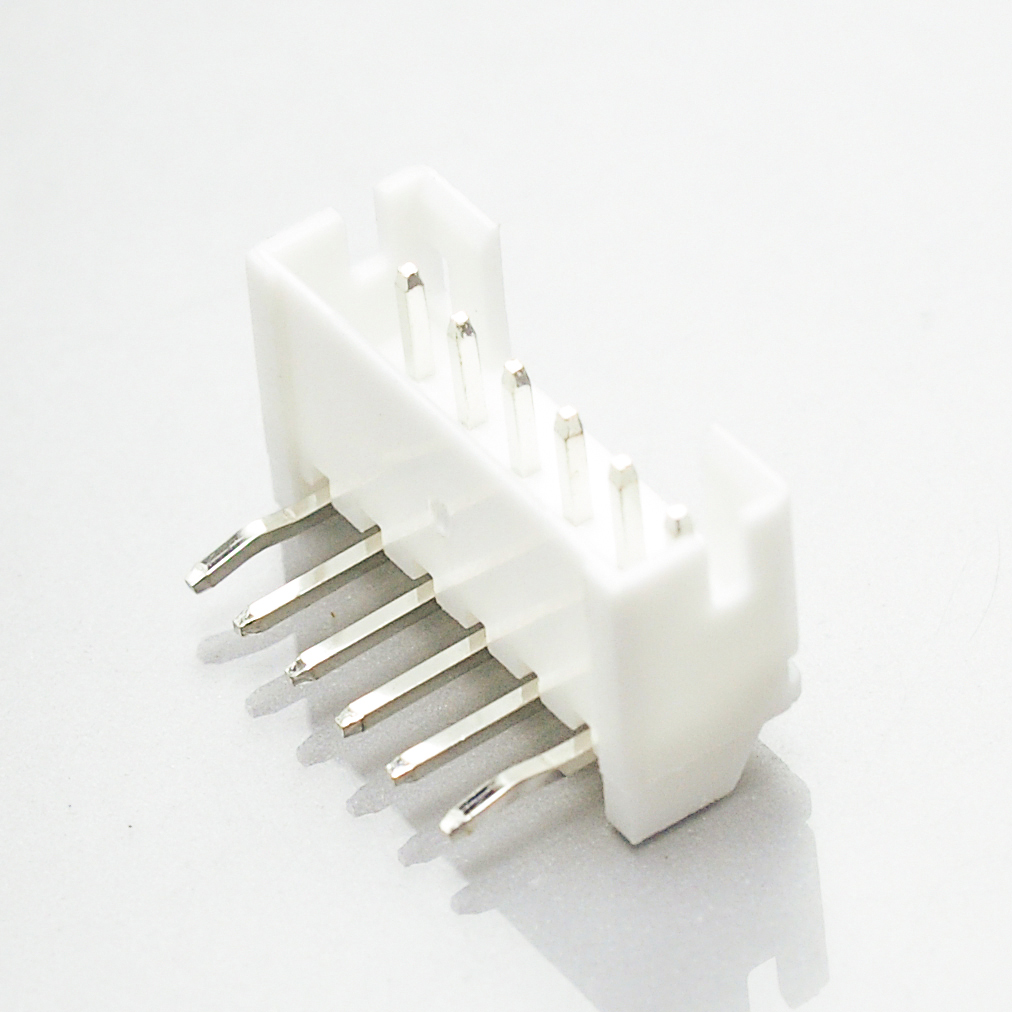
KR2001 DIP right-angle wafer
Cross-reference checklist: ten things to verify before you commit
Work through these in order. Each one corresponds to a specific difference, contradiction or open question identified in this guide.
| # | Check | Why |
|---|---|---|
| 1 | Confirm your wire gauge is inside AWG #24–28 | The KR2001’s published range stops at #28. AWG #30 and #32 are inside JST’s range and outside KONNRA’s. The KR2001 product page incorrectly claims #32 support — use PS-KR2001-01 §4.0 instead. |
| 2 | Measure your wire’s insulation O.D. | JST publishes windows (0.5–0.9mm and 0.8–1.5mm); the KR2001 publishes a 1.5mm maximum. A wire below 0.8mm falls in the JST fine-wire window and has no KR2001 equivalent. |
| 3 | Cite −40°C to +105°C, and cite it from the specification | The page’s General Specification table and PS-KR2001-01 agree at −40/+105°C and match JST. The page’s Overview paragraph wrongly says −25°C to +85°C. Do not copy the Overview figure into a qualification file. |
| 4 | State which contact-resistance condition you mean | JST presents 20mΩ max against an “After test” condition; KONNRA specifies 20mΩ max initial and 40mΩ max after environmental exposure. Same figure, different measurement point. |
| 5 | Decide the DIP retention method: undefined or no undefined |
KONNRA’s DIP wafers come as C2001RD***01T0101PB (“No K”) and C2001RD***01T0102PB (“Have K”). The DIP wafer has no solder tab, so board retention comes from the clinched posts. JST writes the same option as K in its part number. |
| 6 | Check whether you need a solder tab, and therefore SMT rather than DIP | KONNRA lists a brass solder nail on the SMT wafer and “solder tab: none” on the DIP wafer. If your design relies on a nail, the mounting style changes. |
| 7 | Verify board thickness against 0.8–1.6mm | That is JST’s published applicable range. KONNRA does not publish one — so the figure has to come from the original, or from us in writing. |
| 8 | Confirm the footprint mirroring and hole geometry | JST’s layout is drawn from the connector mounting surface, and the hole dimensions are explicitly “for reference only” with fiberglass-cloth laminate needing a larger hole. Compare the KR2001 drawing’s ±0.05mm layout tolerance against your board. |
| 9 | Set crimp acceptance per gauge, and per contact | Conductor crimp height is ±0.05mm and steps 0.10mm per gauge; crimp strength falls from 3.63 to 1.36 kgf across the range. If you use a JST low-insertion-force contact, note that its crimp height differs from the standard contact. |
| 10 | If your product is certified to a standard, check the registered specification | JST states that “Specifications registered to overseas standards may differ from the general specifications listed above.” The certified figure governs, and it may not be the datasheet figure you are comparing against. |
Items 1, 3 and 5 are the three that most often produce a wrong part or a wrong document. Item 1 is a wire-gauge decision, item 3 is a documentation error on the supplier’s own page, and item 5 is a mechanical option that appears in the part number and nowhere else.
Frequently asked questions from procurement and engineering
Is the KR2001 a drop-in replacement for JST PH? On the electrical core it is the closest match we have documented on any series: 100V, 2A at AWG #24, −40°C to +105°C, 20mΩ contact resistance, 1,000MΩ insulation resistance and 800V AC/minute withstanding all match JST’s published figures, at matched conditions. It also matches on circuit range (2–16), on the clinched-post option and on the board layout tolerance (±0.05mm). The wire range is where it stops: the KR2001 covers AWG #24–28, so AWG #30 and #32 are not covered. As with any cross-reference, the footprint and the wire-side fit should be verified against the original drawings before anyone calls it a drop-in — send us your footprint and we will compare it.
What is the actual current rating? 2A AC/DC at AWG #24 on both sides. JST writes “2 A AC/DC (AWG #24)”; KONNRA writes “2A (24AWG) AC/DC”. The rating is qualified by the wire gauge on both documents, which is the correct way to publish it — the limit at smaller gauges is the conductor, not the connector. If your design is short of current, moving up a wire gauge is usually the cheapest fix.
Does it cover AWG #30 and AWG #32? No. The KR2001’s published wire range is AWG #24 to #28, stated identically in the product specification §4.0 and on the terminal drawing. JST covers AWG #32 to #24 using three contacts. Note that the KR2001 product page’s Overview paragraph claims AWG #24 to #32 — that claim is contradicted by KONNRA’s own specification and drawing. If you need #30 or #32, ask us before you design it in.
What is the correct temperature range? −40°C to +105°C. That is what PS-KR2001-01 §4.0 states, what all the KR2001 engineering drawings state, what the product page’s own General Specification table states, and what JST’s datasheet states. The −25°C to +85°C figure in the page’s Overview paragraph is wrong and should not be used.
Does it have a lock? No. PH is a friction-retention system: the housing engages the shrouded header and holds by friction, with no positive latch. If your specification requires a locking connector, look at the KR2004 — KONNRA’s “PH 2.0 Wire to Board Connector with Lock”, cross-referencing Yeonho YH200 PH 2.0, same 2.00mm pitch and 2–16 circuits, 2A — but at a 250V rating. Ask us to compare the footprints.
What is the difference between the KR2001 and the KR2004? Both are labelled “PH 2.0” in KONNRA’s catalogue and they are not the same product. The KR2001 cross-references JST PH 2.0 and is rated 100V. The KR2004 cross-references Yeonho YH200 PH 2.0, adds a lock, and is rated 250V. Same pitch, same circuit range, same 2A. If you are sourcing a PH connector, confirm which of the two you are being quoted — the near-identical naming is a real risk on a purchase order.
Should I use JST’s low-insertion-force contact? Only deliberately. JST’s SPH-002T-P0.5L makes insertion and withdrawal easier, and JST warns in the same note that it is “less resistant to vibration” and that its crimp height is different from the standard PH contact. So: it is a good choice on a hand-mated, stationary application, and a poor choice on a vibrating one — and whichever you choose, it needs its own applicator setup.
How many mating cycles does it have? 30 cycles on the KR2001, with contact resistance required to remain at or below 40mΩ afterwards. JST’s PH datasheet as reviewed does not state a mating-cycle figure in its general specification, so if your qualification document needs JST’s number, that is a question for JST rather than a figure we can supply. And note the retention consequence: the KR2001’s withdrawal force falls by a fixed 0.20 kgf over those 30 cycles, which is a 40% loss on a 2-position connector and a 10.5% loss on a 16-position one.
What PCB thickness does it suit? JST specifies 0.8mm to 1.6mm for PH. The KR2001 specification does not publish an applicable board thickness, so the original’s range is the figure to design against unless we confirm otherwise in writing for your specific part number.
Is a gold-plated version available? Yes, on both sides. JST’s contact note says “Contact JST for gold-plated products.” KONNRA publishes the plating as an ordering-code option: T01 tin-plated, B01 selective gold, G03 gold 3µ”, S00 unplated. So on the KR2001 the choice is a written part-number suffix rather than a special request.
What are the lead time and MOQ? KONNRA can deliver complete connector set samples within 45 days. Connector production lead time is typically 2–3 weeks, and wiring harness assemblies are quoted separately. MOQ depends on the circuit count, the mounting style, the wafer orientation and the plating — send the specific configuration and it will be quoted against the actual part numbers.
Which standards does it carry? JST PH is RoHS2 compliant, and JST directs customers to its “List of Registered Overseas Standards” for UL, CSA and similar registrations — the datasheet does not carry a file number directly. KONNRA’s KR2001 specification does not publish a UL or CSA file number. If your product requires a recognised component, ask for the certification status of the specific part numbers you intend to use — and note JST’s own warning that “specifications registered to overseas standards may differ from the general specifications.”
What is the difference between the KR2001 and the KR2002? Different originals. The KR2001 cross-references the JST PH 2.0 — 2A, 100V, 2–16 circuits, 2.00mm pitch. The KR2002 cross-references IL-S at the same 2A, 100V and 2–16 circuits. They share a pitch and an electrical envelope and are different connector systems. See our other 2.00mm and adjacent-pitch series guides, including the Molex MicroBlade 2.0 connector guide, the Molex CLIK-Mate 1.5 connector guide and the JST SZN 1.5 connector guide.
Start your cross-reference check
Send us the four things below and we will come back with a specific answer rather than a catalogue page — including, if you send the drawing, a footprint comparison against the PH part you are replacing:
- Your wire gauge and measured insulation O.D. — we will confirm it against the KR2001’s AWG #24–28 range and 1.5mm maximum, and tell you plainly if it falls outside
- Your circuit count and the mounting style you need — SMT or DIP, straight or right angle, clinched post or not
- Your board: thickness, and the existing PH footprint or drawing
- Whether your specification needs a lock, and your working voltage
From that we can confirm the housing, terminal and wafer part numbers, the crimp specification, the insertion and withdrawal forces at your circuit count, and — where a figure in our published material differs from the original, such as the temperature range quoted in our product page’s Overview — give you a written answer against the controlled specification.
- Request a quote — KR2001 pricing, MOQ and configuration for your circuit count, mounting style and plating
- Request a sample — complete connector set samples delivered within 45 days
- Request a cross-reference and footprint check — send your PH drawing or footprint and we will compare the dimensions, the board thickness assumptions and the hole geometry against the KR2001
- Request the documents — engineering drawing (PDF), product specification PS-KR2001-01 (PDF) and package specification (PDF)
- Request a crimp specification sheet — conductor and insulation crimp heights, widths and pull-strength requirements for 24, 26 and 28 AWG, with the stripping length
- Request a plating option sheet — the T01 / B01 / G03 / S00 ordering codes and what each one means for your application
- Request a lock comparison — if your specification needs a positive lock, we will compare the KR2004 against your PH footprint and voltage requirement
- Request a vendor qualification pack — test capability summary, quality documentation and certification status
- Request assembled harnesses — KR2001 assemblies crimped and tested to the specification above
- Submit a drawing for review — we will flag any specification mismatch before you commit tooling
Contact KONNRA Electronics
- Phone: (86)-769-85449875
- Email: info@konnra.com
- Address: No.6 Nanchang South Road, Chijiao, Wangniudun, Dongguan, Guangdong, China
- Contact us
Orderable components: KR2001 Housing · KR2001 Terminal · KR2001 SMT Straight Wafer · KR2001 SMT Right Angle Wafer · KR2001 DIP Straight Wafer · KR2001 DIP Right Angle Wafer
➡️ Explore the full 2.0mm pitch range · Wire-to-Board connector category · JST connector cross-reference: 20+ series
Sources and method
This guide compares the original manufacturer’s published documentation with KONNRA’s own published documentation for the cross-reference part. Where the two disagree, both figures are shown and the discrepancy is stated rather than resolved by preference.
Original manufacturer (JST) — PH series:
- JST PH connector datasheet (
ePH.pdf), JST product documentation. Used for: the series description (“2.0 mm pitch/Wire-to-Board connectors/Crimp style and Mating style”); mounting height 8mm and top-entry width 4.5mm; current rating 2A AC/DC (AWG #24); voltage rating 100V AC/DC; “Boxed-shaped shrouded header”; “Space-saving design”; temperature range −40°C to +105°C including temperature rise under current; contact resistance 20mΩ max presented against an “After test” condition; withstanding voltage 800V AC for one minute with no breakdown or flashover; insulation resistance 1,000MΩ min; applicable wire range conductor size AWG #32 to #24 with insulation O.D. φ0.5mm to φ1.5mm; applicable PC board thickness 0.8mm to 1.6mm; RoHS2 compliance; the board layout notes (“viewed from the connector mounting surface”, ±0.05mm hole pitch tolerance non-cumulative, and the hole-dimension caveat including the fiberglass-cloth guidance); the note that “specifications registered to overseas standards may differ from the general specifications”; and the model-number allocation rules. - JST contact tables:
SPH-004T-P0.5S(AWG #32–28, insulation 0.5–0.9mm, 10,000/reel),SPH-002T-P0.5S(AWG #30–24, insulation 0.8–1.5mm, 8,000/reel) andSPH-002T-P0.5L(AWG #28–24, insulation 0.8–1.5mm), with material and finish (copper alloy, tin-plated), the note “Contact JST for gold-plated products”, and the full low-insertion-force caveat covering vibration resistance and the different crimp height. - JST crimping machine tables:
AP-K2N,MKS-L-10,MKS-L,APLMK SPH004-05S,APLMK SPH002-05S,APLMK SPH002-05L, and the note directing customers to JST for a fully automatic crimping applicator. - JST housing table (
PHR-2toPHR-16, A 2.0–30.0mm, B 5.8–33.8mm, 2,000 per bag for 2–7 circuits and 1,000 for 8–16, material PA natural white) with the full colour allocation list; through-hole header tables (B2B-PH-K-StoB16B-PH-K-Stop entry,S2B-PH-K-StoS16B-PH-K-Sside entry, A 2.0–30.0mm, B 5.9–33.9mm, post copper alloy tin-plated, base housing PA natural white); and SMT header tables (B2B-PH-SM4-TBtoB16B-PH-SM4-TBtop entry,S2B-PH-SM4-TBtoS15B-PH-SM4-TBside entry, with post, housing and reinforcement materials, the PA heat-resistance housing in natural ivory, the (LF)(SN) labelling note and the suction-tape option).
Cross-reference manufacturer (KONNRA) — KR2001 series:
- Product specification PS-KR2001-01, Edition A1, issued and revised 2022/2/26, Engineering Dept., Dongguan Konnra Electronics Co., Ltd, seven pages. Used for: §2.0 part-number table (housing
H200101****01F, terminalT20010******A, wafersC2001VS1*********R*,C2001RS1*********R*,C2001RD1**01T01**PB,C2001VD1**01T01**PB); §3.0 materials and surface treatment including “Solder tab: None” for the DIP wafer and the brass solder tab for the SMT wafer; §4.0 ratings (100V AC/DC, 2A (24AWG) AC/DC, −40°C ~ +105°C, AWG 24#–28# with insulation O.D. 1.50mm max); §5.1 contact resistance 20 milliohms max by dry circuit at 20mV / 100mA to EIA-364-23C; §5.2 insulation resistance 1000 megohms min at 500V DC for one minute to EIA-364-21B; §5.3 dielectric strength 800V AC for one minute to EIA-364-20A; §6.2 terminal insertion force 0.5 kgf (4.9N) max; §6.3 terminal/housing retention 1.0 kgf (9.8N) min; §6.4 pin retention 1.0 kgf (9.8N) min; §6.5 the crimp specification for 24/26/28 AWG including crimp widths and heights, crimp strength (3.63 / 2.27 / 1.36 kgf min) and stripping length (1.5–2.0mm); §7.1–7.11 environmental performance including durability (30 cycles, 40mΩ max after), temperature rise (30°C max), vibration (1.5mm P-P, 2 hours per axis, 1 microsecond maximum discontinuity), shock (490 m/s² (50g)), heat (105 ± 2°C, 96 hours), cold (−40 ± 2°C, 96 hours), humidity (40 ± 2°C, 90–95% RH, 96 hours, with 100 megohms min insulation resistance after), thermal shock (5 cycles), salt spray (24 hours), solderability (245 ± 5°C, 3 ± 0.5s, 95% of immersed area) and solder resistance; §8.0 the insertion and withdrawal force table for 2–16 circuits, both initial and at 30 cycles; §9.1 the SMT infrared reflow profile and §9.2 the wave soldering profile; and §10.0 the remark. - Engineering drawings, KR2001 series:
2001H01-F-S(housing, Rev A02, title “JST PH 2.0_HSG”, material Nylon 66 UL94 V-0, dimension table for 2–16 circuits);2001T101-A-S(terminal, Rev A02, title “PH2.0 Terminal”, phosphor bronze or brass, tin-plated over nickel, applicable wires AWG #28~#24, insulation O.D. 1.5mm max, 10,000 pcs per reel, with the plating ordering codes T01 / B01 / G03 / S00);2001WRD101-B-Sand2001WRD102-B-S(DIP 90° wafer, part numbersC2001RD***01T0101PB“No K” andC2001RD***01T0102PB“Have K”);2001WVD101-B-S(DIP 180° wafer,C2001VD***01T0101PB“Have K”);2001WHS01-C-S(SMT 90° wafer, Rev A6, Nylon 9T or LCP insulator, brass contact and solder nail);2001WVS101-C-S,2001WVS101-F-Sand2001WVS101G-C-S(SMT 180° wafers, including the B-mould and Type-C variants with and without CAP). Used for: the specification blocks (2A, 100V, −40°C ~ +105°C, 1,000MΩ min, 800V AC/minute, 20mΩ max); the materials (PA66, PA9T, LCP, brass, tin over nickel); the SQ 0.50 ± 0.05 post size and φ0.80 board hole; the recommended PCB layout total tolerance of ±0.05mm; the ordering-code conventions including the circuit codes; and the general tolerance block X.X ±0.30 / X.XX ±0.20 / X.XXX ±0.10 / angle ±2°. - KR2001 product pages — published at two URLs with identical content:
/product/kr2001-equivalent-to-jst-ph2-0-alternatives-connector/and/product/kr2001-series-ph-2-0-wire-to-board-crimp-connector/. Used for: the page specification table (pitch 2.0mm, circuits 2–16pin, current 2A, voltage 100V); the General Specifaction table (materials, insulation O.D. 1.5mm max, withstanding 800V AC/minute, temperature range −40℃~+105℃, contact resistance and insulation resistance figures, plating); the Overview paragraph that states “AWG#24 to AWG#32” and “−25°C to +85°C” — both of which are contradicted by KONNRA’s own specification and drawings; the Advantages section; component page links; document download links; and the image set. - KONNRA 2.0mm pitch index page. Used for the cross-reference positioning of the sibling 2.00mm series (KR2002, KR2003, KR2004, KR2005, KR2007, KR2009, KR2014, KR2017, KR2022, KR2023) in the pitch-class comparison table, and for the KR2004 entry described as “KR2004 Series PH 2.0 Wire to Board Connector with Lock”.
Not published in any source reviewed: the JST PH mating-cycle (durability) rating; the JST PH insertion and withdrawal force table; the JST PH terminal insertion, terminal retention and pin retention forces; the JST PH temperature rise, vibration, shock, heat, cold, humidity, thermal shock and salt spray requirements; the JST PH crimp dimensions; and a UL or CSA file number on either manufacturer’s English-language datasheet. On the KONNRA side, the applicable PCB thickness, mounting height, top-entry width and shrouded status for the KR2001 are not published. Where KONNRA’s product page contradicts its own controlled documents — on the wire range and on the temperature range — the controlled documents are reported as the figures to design against and both published versions are shown.
Method note. Figures were taken from controlled or manufacturer-published documents where available and from product pages only where no controlled document exists. The wire range was compared gauge by gauge across both manufacturers’ contact tables rather than as a headline range, which is how the AWG #30 and #32 gap was identified. The insertion and withdrawal force tables were analysed as sequences rather than as isolated values; the insertion force was found to rise by exactly 0.50 kgf per circuit and the initial withdrawal force by exactly 0.10 kgf per circuit, with no exceptions across the 2-to-16 range, and the post-30-cycle withdrawal values were found to be exactly 0.20 kgf below the initial values at all fifteen position counts, with the resulting percentage losses calculated from the published figures. Dimensional tables were transcribed and compared; the KR2001 housing’s outer length (the C dimension) was found to match JST’s PHR housing B dimension exactly at every circuit count from 2 to 16, and this is reported as an observation on the overall length rather than as a claim about intermediate dimensions that JST does not publish. The two identical KR2001 product pages are reported as a duplicate publication rather than resolved.