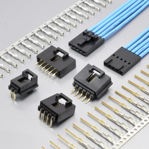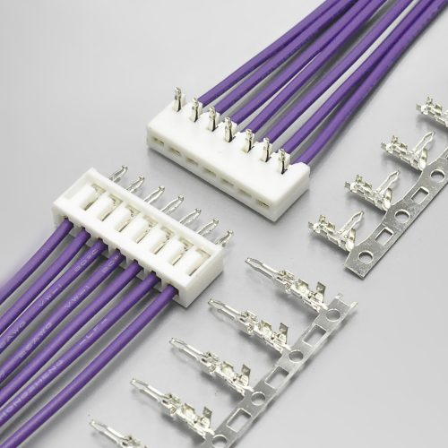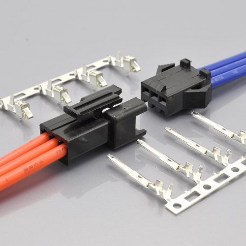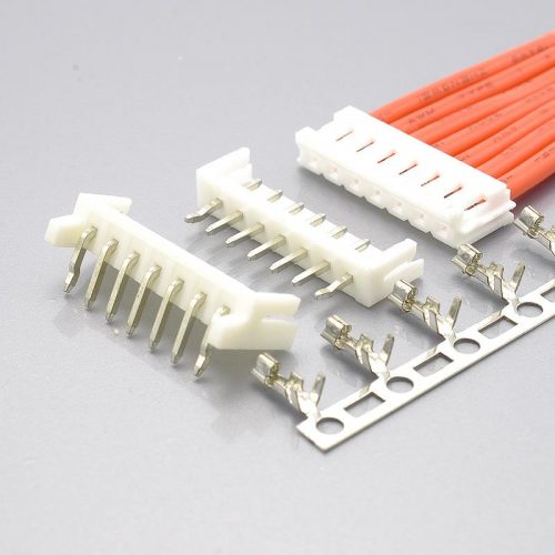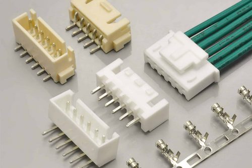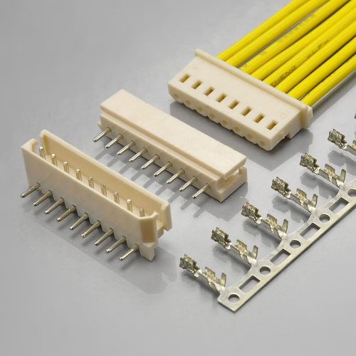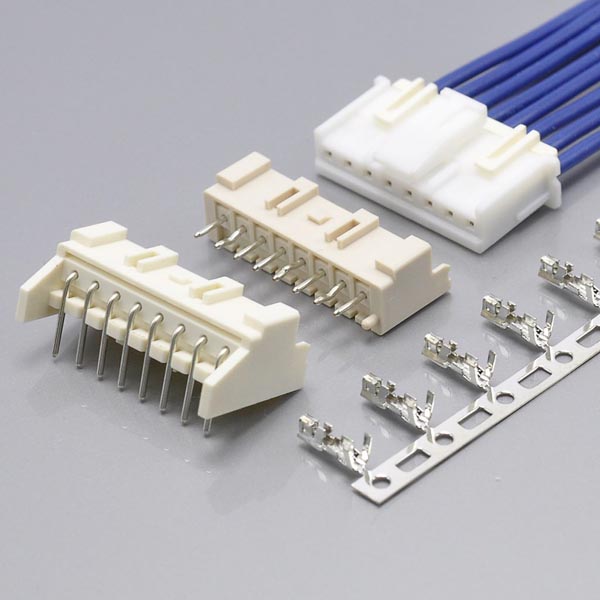
Quick answer: The JST XA is a 2.5mm pitch, single-row, locking wire-to-board crimp connector — the family JST builds for connections that have to stay mated under vibration and wire routing. It pairs a crimp housing, a crimp terminal and a through-hole or SMT header, and it adds two things its 2.5mm neighbours do not have: a secure lock in both outer and centre positions, and an optional secondary retainer. JST rates it 3A AC/DC (AWG #22 and AWG #20) at 250V AC/DC, over −40℃ to +105℃, with 1,000MΩ minimum insulation resistance, 1,000 VAC for one minute withstanding voltage, 10mΩ maximum initial contact resistance, an applicable conductor range of AWG #28 to #20 (0.08 to 0.5mm²) and an insulation window of φ0.8mm to φ1.9mm. The KONNRA KR2516 is the cross-reference equivalent, and it is the closest match on the electrical sheet in this series of comparisons: the withstanding voltage, the insulation resistance, the 250V rating, the −40℃ to +105℃ temperature range and the 10mΩ initial contact resistance all agree, and the 1.9mm insulation ceiling is identical. Three things do not match. The KR2516 documents AWG 22# to 28#, so AWG #20 — which JST rates the same 3A on — is not covered. It documents 2 to 15 circuits where JST offers 2 to 15 plus 18 and 20. And the retainer is claimed in our own product title, but no retainer and no retainer-compatible housing appears in any cross-reference table we publish. There is also one internal contradiction to fix: our product page states the temperature range as −40℃ to +105℃ in its specification table and −25℃ to +85℃ in the prose directly beneath it.
I work on connector and harness programmes at KONNRA, so treat the disclosure as read. Everything below comes from manufacturer documents on both sides, and where they disagree I have said so rather than averaged.
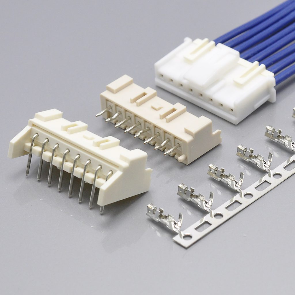
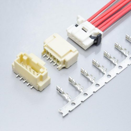
KONNRA KR2516 series XA 2.5 wire-to-board TPA electronic cable connector
What the JST XA 2.5 Connector Actually Is
Every 2.5mm crimp family looks similar in a catalogue photograph. The XA is worth separating from its neighbours before any cross-reference is attempted, because its defining feature is not the pitch, the current or the voltage — it is the lock.
JST’s own product profile describes the series in six lines, and five of them are about retention or assembly rather than electrical performance:
- “Secure lock mechanism” — a positive latch, not friction
- “Solder crack preventive material” — the header body is specified in glass-filled resin
- “Low insertion force” — JST also lists a dedicated low-insertion-force contact,
SXA-001T-P0.6L - “Keyed housing structure to guide mating process” — the housing is keyed so it can only go on one way
- “Compatible with pick and place machine for automatic PCB assembly” — headers are available in tape and reel
- “Headers with boss available for polarization”
And the product profile adds a row that most 2.5mm families do not have at all: Retainer — Retainer. That single word is the reason this guide has a section of its own on the retainer further down, and it is where our own documentation is weakest.
JST files the series as Crimp Style Connectors (Wire-to-Board type), with PC board mounting: through-hole, SMT, mating direction: side entry, top entry, a single-row array, and two connection variations worth noting: a compatible IDC connector is available (the XAF connector) and a wire-to-wire type is available.
The three parts, and why the count matters
| Part | JST family | What it does |
|---|---|---|
| Terminal | SXA-…T-P0.6 |
Crimped to the wire; three part numbers cover three wire ranges |
| Housing | XAP-…V-1 (standard) and XARP-…V (retainer-compatible) |
Carries the crimped terminals; the wire side of the connection |
| Header / wafer | B…B-XASK-1 (top entry), S…B-XASK-1 / S…B-XASS-1N-BN (side entry), BM…B-XASS-TF (SMT) |
Solders to the board; the mating half |
| Retainer | XMS-…V |
The secondary lock, fitted after the terminals are seated |
Four part families rather than three, and that is the structural difference from every other 2.5mm cross-reference I have written. In the XH comparison the parts were a wafer, a housing and a terminal; in the EH comparison the same; in the Yeonho comparison the same. Here there is an extra component whose only job is to hold the terminals in — and, as the next section shows, its existence also decides which circuit counts JST will sell you.
JST XA 2.5 Key Specifications at a Glance
| Attribute | JST XA (manufacturer) | KONNRA KR2516 | Verdict |
|---|---|---|---|
| Pitch | 2.5mm | 2.50mm | Match |
| Architecture | Wire-to-board crimp — housing, terminal, header | Wire-to-board crimp — housing, terminal, wafer | Match |
| Locking | Secure lock (outer), secure lock (centre), keyed housing | Secure locking mechanism | Match in principle — see the retainer section |
| Current / voltage | 3A AC/DC (AWG #22, AWG #20) / 250V AC/DC | 3A / 250V | Rating matches; reference conductor not published |
| Withstanding voltage | 1,000 VAC for one minute | 1000V AC/ minute | Match |
| Insulation resistance | 1,000MΩ min. | 1000MΩ Min | Match |
| Contact resistance | Initial 10mΩ max.; after test 20mΩ max. | 10mΩ Max | Matches the initial value; after-test not published |
| Temperature range | −40℃ to +105℃ (including temperature rise) | −40℃~+105℃ (table) / −25℃ to +85℃ (prose) | Table matches; our own page disagrees with itself |
| Conductor size | AWG #28, #26, #24, #22, #20 (0.08–0.5mm²) | 22#–28# | AWG #20 missing |
| Insulation O.D. | φ0.8mm to φ1.9mm | 1.9mm (MAX) | Ceiling identical; no floor |
| Applicable PC board thickness | 1.6mm | Not published | Original only |
| Circuits | 2 to 15, plus 18 and 20 | 2 to 15 | 18 and 20 missing |
| Retainer (TPA) | XMS-02V … XMS-15V | Not published | Original only |
| Retainer-compatible housings | XARP-02V … XARP-18V | Not published | Original only |
| SMT header | BM02B-XASS-TF … BM15B-XASS-TF | Not published (DIP only) | Original only |
| Header base material | PA (GF) / PA (Heat Resistance) for SMT | PA66, UL94 V-0 | Glass-fill not called out |
| Terminal material | Pin: copper alloy, tin-plated | PIN: Brass, tin over nickel | Close — alloy callout differs |
| Agency | CSA, TÜV, UL | UL E482542 | Partial |
| Product specification document | Catalogue with specifications, part numbers, board layout, packaging and tooling | Not published — drawings only | Document gap |
Both columns come from manufacturer documents. Sources are listed at the end.
What Matches Exactly
This is the strongest set of agreements in this series, and one of them is a genuine surprise.
| Figure | JST XA | KONNRA KR2516 |
|---|---|---|
| Withstanding voltage | 1,000 VAC for one minute | 1000V AC/ minute |
| Insulation resistance | 1,000MΩ min. | 1000MΩ Min |
| Voltage rating | 250V AC/DC | 250V |
| Temperature range | −40℃ to +105℃ | −40℃~+105℃ |
| Contact resistance (initial) | 10mΩ max. | 10mΩ Max |
| Insulation O.D. ceiling | φ1.9mm | 1.9mm (MAX) |
| Pitch | 2.5mm | 2.50mm |
The withstanding voltage is the one to lead with, because in this series of comparisons it is usually where cross-references go wrong. JST requires that there be “no breakdown or flashover while applying 1,000 VAC for one minute”. The KR2516’s product page publishes 1000V AC/ minute in the General Specification table and repeats “withstanding voltage spikes of up to 1,000VAC per minute” in the Overview prose. Original and equivalent agree, and they agree in both places on our side.
Note the contrast with the XH comparison, where exactly this row was wrong. In the KR2501 guide the withstanding figure was correct in the specification and wrong on the product page — the page carried the 250V rated voltage in the withstand row. Here there is no such split. That is worth stating plainly: the same class of error does not appear in every product, which is the reason each of these comparisons is written from the documents rather than from the previous one.
The 1,000MΩ insulation resistance is a match, and it is worth noticing both because of what it is compared against. JST publishes 1,000MΩ min. for the XA; the KR2516 publishes 1000MΩ Min on the product page and on all four component pages. JST’s other 2.5mm families in this series do not all carry this figure — the SM family, in the wire-to-wire comparison, is specified at 500MΩ — so 1,000MΩ is a real number in the original’s own documents rather than a house default.
The contact resistance agrees on the initial value, and the comparison is unusual because JST publishes two figures and we publish one. JST’s specification block reads “Contact resistance: Initial value / 10 mΩ max. After test / 20 mΩ max.” The KR2516 publishes 10mΩ Max. So our published limit is the original’s initial limit, and the after-test limit has no counterpart on our side — not because it is worse, but because it is not published. Ask for it in writing if your qualification file has a post-conditioning contact-resistance budget; it is the kind of figure an automotive or appliance customer will ask for and the kind that a connector datasheet is expected to carry.
And the temperature range matches — which is the headline finding of this guide. The next section is about why that is more interesting than it sounds.
Temperature: the divergence that has followed this series for five rounds is absent here
For five previous comparisons in this series, the temperature range has been the single most consistent divergence between the original and our equivalent — and always in the same direction:
| Comparison | Original’s rating | KONNRA rating | Gap |
|---|---|---|---|
| JST XH (KR2501) | −25℃ to +85℃ | −40℃ to +105℃ | 20℃ wider at the hot end |
| Yeonho YH 2.5 (KR2502) | −25℃ to +85℃ | −40℃ to +105℃ | 20℃ wider |
| JST EH (KR2504) | −25℃ to +85℃ | −40℃ to +105℃ | 20℃ wider |
| JST SM (KR2507) | −25℃ to +85℃ | −40℃ to +105℃ | 20℃ wider |
| JST SCN (KR2508) | −25℃ to +85℃ | −40℃ to +105℃ | 20℃ wider |
| JST XA — this guide | −40℃ to +105℃ | −40℃ to +105℃ | None |
The XA is the first original in this series whose own catalogue reads −40℃ to +105℃. JST’s specification block states it as including the temperature rise from applied current, which is the same basis our own figure is written on. So there is nothing to reconcile: the widest recurring divergence in this series simply does not occur here.
That is worth more than a row in a table, because it is evidence about the previous five rounds. When the same 20℃ gap appeared against five different originals from four manufacturers, the honest reading was that the gap said something about a house rating rather than about any of those five parts — and the right conclusion was that a wider range is a claim to be supported rather than a specification to be inherited. The XA adds the other half of that argument: the house figure is not a template that gets applied regardless of the original. Where the original itself is rated to +105℃, our documentation says +105℃. That is the correct behaviour, and it is easy to see now that it occurred.
What to do when +105℃ matters to your design. Ask for the test evidence behind it rather than accepting the row: heat-ageing, thermal shock and the post-conditioning contact-resistance limit at the hot end. JST’s own figure is stated as including temperature rise under load, so the two documents are on the same basis and can be compared directly — which is exactly the situation you want, and the reason to keep the request.
Our own product page states two different temperature ranges
There is one thing to fix before this becomes a clean story, and it is on our side.
| KONNRA document | Temperature range stated |
|---|---|
| Product page, General Specification table | −40℃~+105℃ |
| Product page, Overview paragraph | −25°C to +85°C |
| All four component pages | −40℃~105℃ |
| Terminal page | −40℃~105℃ |
The same page publishes −40℃~+105℃ in its table and −25°C to +85°C four lines below it in prose. The table, the four component pages and the terminal page agree with the original; the Overview paragraph does not. Read the table as controlling — but note which direction the error points. −25℃ to +85℃ is the narrower range, so a designer who takes the prose at face value will believe the part is less capable than the documentation states, and may rule it out or over-specify a more expensive part. It is a conservative-direction error rather than a permissive one, which is the less dangerous kind — and it is still an error, because a qualification file that quotes it will be quoting a figure that the rest of our own documentation contradicts.
The figure is also recognisable. −25℃ to +85℃ is JST’s rating for its 2.5mm families that are not the XA — the XH, EH, SM and SCN, as the table above shows. So the Overview appears to be describing the neighbouring family rather than this one. It is on our correction list, and it is the sort of sentence worth reading against the specification table rather than on its own.
And the Overview is not the only place where a claim and a number need to be read together. It also says the series provides “a wide range of operating temperatures, from −25°C to +85°C, for reliable operation” — the word “wide” attached to the narrower of the two figures the page contains. Same fix.
The Wire Window: AWG #20 Has No Documented Home
| Conductor | JST XA | KONNRA KR2516 |
|---|---|---|
| AWG #20 | ✅ Accepted (0.5mm²) — and JST rates the 3A on #22 and #20 | ❌ Not documented |
| AWG #22 | ✅ Accepted (0.33mm²) | ✅ 22#–28# |
| AWG #24 | ✅ Accepted | ✅ 22#–28# |
| AWG #26 | ✅ Accepted | ✅ 22#–28# |
| AWG #28 | ✅ Accepted (0.08mm²) | ✅ 22#–28# |
JST’s applicable conductor range is AWG #28 to #20 — five sizes. The KR2516 documents 22# to 28# — four. The one that is missing is the heaviest.
Why #20 specifically matters, and why this is a different situation from a conservative rating. JST’s current rating is published as “3 A AC/DC (AWG #22, AWG #20)” — the family’s headline current is referenced to two conductors. So AWG #20 is not an edge case JST tolerates; it is one of the two gauges the 3A rating is qualified on. If your harness uses AWG #20, the KR2516 as documented does not cover it — and it is the conductor on which the original’s headline current rating is most comfortable.
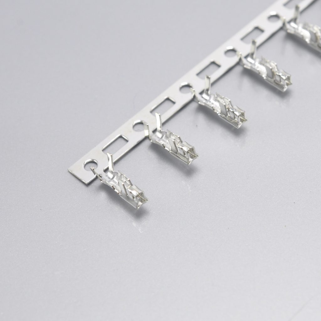
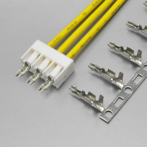
KONNRA KR2516 series 2.50mm pitch crimp terminal for the JST XA pattern
And it is not a single-terminal question, which is the part most easily missed. JST publishes three terminals for this family:
| JST terminal | Conductor size | Insulation O.D. | Qty/reel |
|---|---|---|---|
SXA-001T-P0.6 |
#28 to #22 (0.08–0.33mm²) | 0.8 to 1.9mm | 8,000 |
SXA-01T-P0.6 |
#24 to #20 (0.22–0.5mm²) | 1.5 to 1.9mm | 8,000 |
SXA-001T-P0.6L |
#26 to #22 (0.13–0.33mm²) | 1.3 to 1.7mm | 8,000 |
AWG #20 is served by a different terminal, SXA-01T-P0.6, not by the standard one. Our cross-reference table maps one KONNRA terminal, T25160PT0101A, to SXA-001T-P0.6 — the lighter-wire part. So the question “can you cover AWG #20?” is not a matter of relaxing a window; it is a question about a second terminal and its own crimp tooling. JST’s own tooling list confirms the split: the applicator for SXA-001T-P0.6 is CDS SXA/M001-06/CMKS-L, and the applicator for SXA-01T-P0.6 is a different part, CDS SXA/M01-06/CMKS-L, with different hand tools (WC-692 against WC-700M). Ask us about the AWG #20 terminal and its tooling together, at quotation—not after the harness drawing is released.
One more detail in that table is worth reading, because it is the direction of travel in the family. The three terminals’ insulation windows are 0.8–1.9mm, 1.5–1.9mm and 1.3–1.7mm — the window moves with the wire, not against it. Heavier wire needs a larger minimum insulation diameter because the insulation wall around a #20 conductor cannot be as thin in absolute terms. That is the mechanism behind the insulation question in the next section, and it is why the two questions cannot be collapsed into one.
The Insulation Window: the Ceiling Is Identical, the Floor Is Missing
| Source | Applicable wire insulation O.D. |
|---|---|
| JST XA catalogue | φ0.8mm to φ1.9mm |
| JST SXA-001T-P0.6 terminal | 0.8 to 1.9mm |
| JST SXA-01T-P0.6 terminal | 1.5 to 1.9mm |
| KR2516 product page, General Specification | 1.9mm (MAX) |
| KR2516 terminal component page | Insulation Diameter 1.9mm(MAX) |
The ceiling is an exact match at 1.9mm. The floor — and it is φ0.8mm — is unaddressed. Nothing in the KR2516 documentation states a lower bound, so the whole lower half of the original’s window is undocumented on our side rather than answered.
This is a narrower gap than most in the series, and it is worth saying so. In the SM comparison the ceiling itself was 1.6mm against an original 1.8mm — a genuine restriction; in the EH and Yeonho comparisons the ceilings were equal and only the floor was missing. The XA is in the second group: 1.9mm against 1.9mm, with φ0.8mm unanswered. So this is a documentation gap rather than a capability gap, which is a better place to be — and it is still a gap, because an engineer measuring a thin-insulation wire at 1.0mm cannot confirm from our documents that it will crimp correctly.
The risk of leaving it undocumented is the one that fails quietly. An insulation barrel sized for the top of the range closes on the insulation of a thin-insulated wire without gripping anything; the joint passes a continuity check, ships, and pulls free later. The failure is mechanical, it is delayed, and it does not appear at end-of-line test — which is exactly why the floor belongs in the document rather than in an assumption.
And the practical instruction is the same as in every guide in this series: measure the actual insulation outside diameter of the wire on your harness drawing — not the nominal, not the gauge — and confirm it in writing against the terminal you are quoting. On the XA the ceiling is not the question. The floor is.
Circuits: 2 to 15, Plus Two Counts That Live in Different Families
JST’s circuit ladder for the XA is unusual, and the reason is the retainer.
| Source | Circuits |
|---|---|
| JST XA product profile | 2, 3, 4, 5, 6, 7, 8, 9, 10, 11, 12, 13, 14, 15, 18, 20 |
| KR2516 product page | 2-15pin |
| KR2516 straight wafer page | 2P~15P |
| KR2516 right-angle wafer page | 2P~15P (its cross-reference table stops at 14) |
JST catalogues the XA from 2 to 15, and then adds 18 and 20 as separate options. The KR2516 documents 2 to 15. So the count range is a clean subset with two positions missing at the top — and the two missing positions are not simply “longer versions of the same part”:
| Circuits | Standard housing | Retainer-compatible housing | Top-entry header | Side-entry header |
|---|---|---|---|---|
| 2 to 15 | XAP-02V-1 … XAP-15V-1 |
XARP-02V … XARP-15V |
B…B-XASK-1 |
S…B-XASK-1 (3–14) |
| 18 | Not available | XARP-18V only | B18B-XASK-1N |
Not available |
| 20 | XAP-20V-1 only | Not available | B20B-XASK-1 |
Not available |
Read that table carefully, because it is the least obvious structure in the family: the 18-way exists only in the retainer-compatible housing, and the 20-way exists only in the standard one. They are not alternatives to each other on the same base part — the retainer is what defines whether the 18-way exists at all. JST’s own householding shows it: XARP-18V is listed under the retainer-compatible type with no standard-type counterpart, and XAP-20V-1 is listed under the standard type with no retainer-compatible counterpart.
And 15 was never coming to the side-entry header. JST’s side-entry tables stop at 14 circuits in both the hook and the /N type; the 15-way is a top-entry option. Our right-angle wafer cross-reference stops at 14 as well — which is correct, and worth noticing as a point in our favour, because it is the kind of thing a table can get wrong by simply continuing. What is inconsistent is the same page’s own summary row: it states Number of Positions: 2P~15P while its cross-reference table ends at 14. A designer scanning the feature block will assume a 15-way exists in right-angle; the table on the same page says it does not.
So the honest summary on circuits is this: our documented 2 to 15 is a correct subset across the whole family, and JST’s 18 and 20 are not covered. If your design needs either, ask — the answer is a housing and header question rather than a pin-count question, and on the original side an 18-way and a 20-way are not interchangeable parts of the same ladder.
The Retainer: a Feature in Our Product Title With No Part Number Behind It
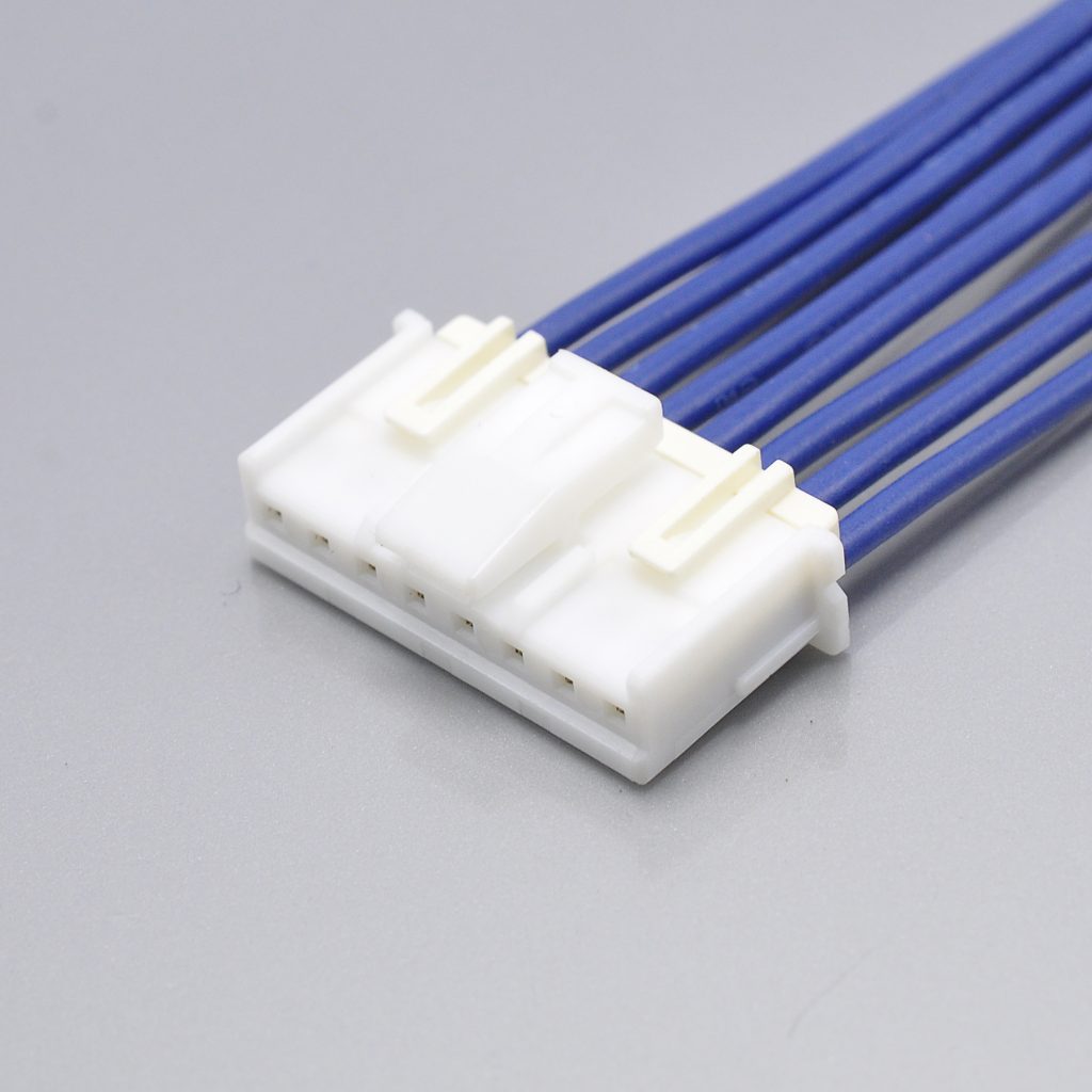
KONNRA KR2516 series 2.50mm pitch crimp housing for the JST XA pattern
A retainer — often called a TPA device, for terminal position assurance — is a small plastic part that clips over the back of a housing after the crimped terminals have been seated. It is a secondary lock: the terminal’s own lance holds it in place, and the retainer stops a partially-seated terminal from travelling. On a connector that has to survive wire routing and vibration, it is the difference between a latch that relies on one moulded feature and a connection that has two independent retention systems.
JST offers one for the XA. We claim one in our product titles. The gap is in the tables.
| Item | JST XA | KONNRA KR2516 |
|---|---|---|
| Retainer | XMS-02V … XMS-15V (2–15 circuits), PA (GF), natural (ivory) | Not published |
| Retainer-compatible housings | XARP-02V … XARP-18V — a second housing family, alongside the standard XAP-…V-1 |
Not published — our housing cross-reference maps only XAP-…V-1 |
| Product profile row | Retainer — Retainer | — |
| Product page title | — | “…Wire to Board TPA Electronic Cable Connectors” |
| Product page overview text | — | “secure locking mechanism” |
Both of our product page titles for this series contain the word TPA. Neither our product page, our housing page, our wafer pages nor our terminal page publishes a retainer part number, a retainer-compatible housing, or a retainer drawing. So the feature is claimed where a search engine and a buyer will read it, and absent where an engineer would look for the part.
That matters twice over, because on the original side the retainer is not cosmetic. As the circuit table above shows, the 18-way XA exists only in the retainer-compatible housing family — XARP-18V, with no XAP-18V-1 — while the 20-way exists only in the standard family. So on JST’s side the retainer is a housing choice that also decides which circuit counts are available, not an accessory bolted onto an unchanged housing. A cross-reference that offers only XAP-…V-1 therefore cannot offer the 18-way even in principle.
How to close the gap, and what to ask. Send us the design intent — circuits, wire, and whether the harness is routed near a vibration source or a moving part — and ask for the retainer part number explicitly. If TPA is a requirement in your customer’s specification, say so at enquiry: it changes the housing part number on our side as well as yours, and it belongs in the quotation rather than in a drawing revision. If TPA is not required, that is worth stating too, because the claim in our title is currently doing work that our documents do not support.
One more item in the same family of problems. Our media library contains a KR2516 image file titled “KR2516 2.0mm pcb connector with TPA”. This series is 2.50mm. It is a filename rather than a specification, and it still ends up in image search results and in the alt text a buyer may copy. It is on the same correction list as the temperature paragraph.
Reading a JST XA Model Number
The XA uses four part-number families, and the fastest way to avoid a wrong quote is to know which family a number belongs to before looking anything up.
| Prefix pattern | Part | Example | Notes |
|---|---|---|---|
| SXA-…T-P0.6 | Terminal | SXA-001T-P0.6, SXA-01T-P0.6, SXA-001T-P0.6L |
Three wire ranges; the L suffix is the low insertion force contact |
| XAP-…V-1 | Housing, standard | XAP-04V-1 |
The default wire-side part |
| XARP-…V | Housing, retainer-compatible | XARP-04V, XARP-18V |
Required if a retainer will be fitted; the only route to 18 circuits |
| XMS-…V | Retainer | XMS-04V |
Fitted after the terminals are seated |
| B…B-XASK-1 | Header, top entry | B04B-XASK-1 |
-A suffix = with polarizing boss; -1N = the /N type |
| S…B-XASK-1 | Header, side entry, with hook | S04B-XASK-1 |
3 to 14 circuits |
| S…B-XASS-1N-BN | Header, side entry, /N type | S04B-XASS-1N-BN |
Without hook, 2 to 14 circuits |
| BM…B-XASS-TF | Header, SMT | BM04B-XASS-TF |
Tape and reel; no KONNRA counterpart |
Three decoding rules hold across all four families, and they are worth knowing before you read a table.
The circuit count sits immediately after the letter block and is zero-padded — XAP-04V-1 is 4 positions, XMS-15V is 15. So two numbers that differ only in the middle digits are different parts, not different documents for the same part.
The suffix is part of the identity, not a packaging note. -A means a polarizing boss; -1N and -BN mark the /N type; -TF is SMT tape and reel; -T is radial taping; -L on a terminal is the low-insertion-force contact. Two numbers that differ only by a suffix are not interchangeable, and this is where the next point comes from.
And (LF)(SN) is a label marking rather than a different product. JST’s catalogue states it directly: “This product displays (LF)(SN) on a label.” If you see S04B-XASK-1(LF)(SN) in a distributor listing and S04B-XASK-1 in a drawing, they are the same part.
One number in our table does not resolve on JST’s side
Our right-angle wafer page lists two JST families, and one of them is written differently from the way JST publishes it:
| Our cross-reference entry | JST’s published model number |
|---|---|
S02B-XASK-1N-BN … S14B-XASK-1N-BN |
S02B-XASS-1N-BN … S14B-XASS-1N-BN |
S02B-XASK-1 … S14B-XASK-1 |
S02B-XASS-1 (2 circuits) / S03B-XASK-1 … S14B-XASK-1 |
JST publishes the /N-type side-entry header with a double S — XASS — and our table renders it XASK. JST’s own product index, its XA catalogue and the distributor listings for this family all give S…B-XASS-1N-BN; a search for S…B-XASK-1N-BN returns nothing. Note that the second row of our own table uses XASK and is correct — JST really does use XASK for the hook-type side-entry header from 3 circuits up, and a genuine anomaly at 2 circuits, where the part is S02B-XASS-1. So the two families genuinely do use different letter blocks, and the distinction is exactly the sort that gets lost when a table is transcribed.
What it costs you. A purchase order, a distributor search or a cross-reference tool fed S04B-XASK-1N-BN will find nothing, and the usual conclusion drawn from that is that the part is obsolete. Read the XASS form. It is on our correction list, and it is the reason this guide names both the family and the full model number for every header rather than only the family.
The Header Variants: hook, /N type, boss, SMT and radial tape
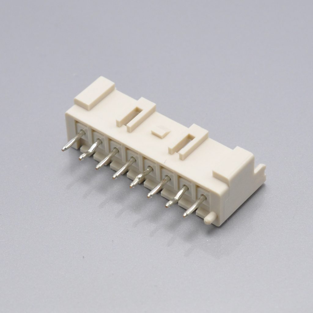
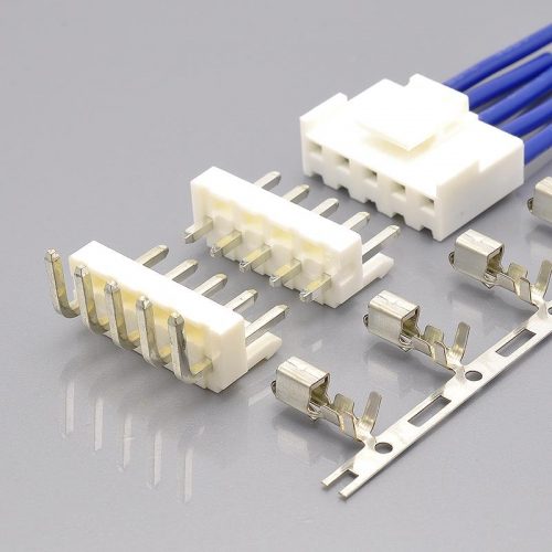
KONNRA KR2516 series straight DIP type wafer, the top-entry header for the JST XA pattern
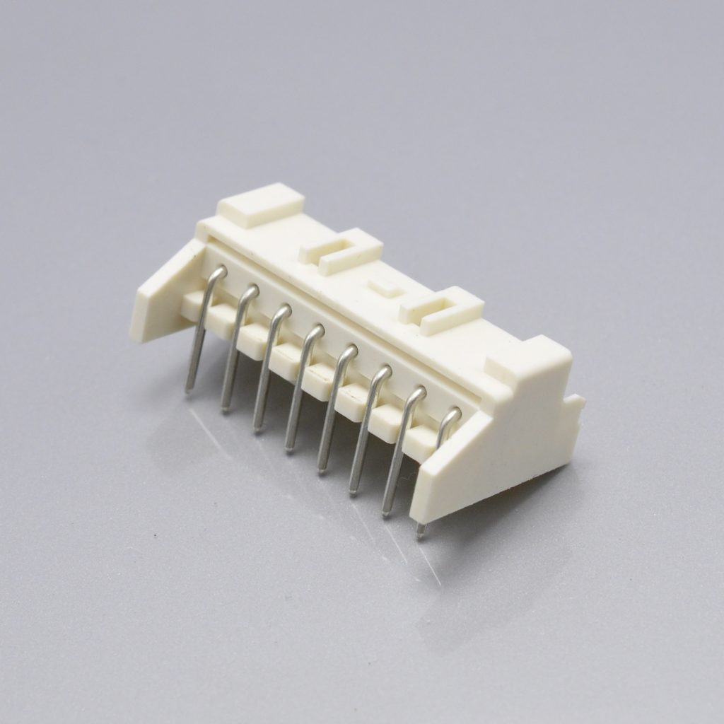
KONNRA KR2516 series right-angle DIP type wafer, the side-entry header for the JST XA pattern
The board half of the XA is the most configurable part of the family, and the variants are not cosmetic. JST publishes five header constructions:
| Construction | JST model numbers | Circuits | KONNRA |
|---|---|---|---|
| Top entry, through-hole | B…B-XASK-1 (plain) / B…B-XASK-1-A (with boss) |
2–15, 20 | Straight wafer C2516VD1… ↔ B…B-XASK |
| Top entry, /N type | B…B-XASK-1N / B…B-XASK-1N-A (with boss) |
2–15, 18 | Not distinguished |
| Side entry, with hook | S02B-XASS-1, S03B-XASK-1 … S14B-XASK-1 |
2–14 | Right-angle wafer C2516RD1… ↔ S…B-XASK-1 |
| Side entry, /N type | S…B-XASS-1N-BN |
2–14 | Right-angle wafer C2516RD1… ↔ S…B-XASK-1N-BN |
| SMT, tape and reel | BM…B-XASS-TF |
2–9, 12, 13, 15 | None |
| Radial taping | B…B-XASS-1-T / -A-T |
2–8 | None |
The hook is a wire-routing device, and JST says so in a note rather than leaving it to the drawing. The catalogue warns that with wire routing, pulling and twisting, “there is a risk that the base pin may separate from the PCB”, that excessive stress “may also affect the solder fillet section on the PCB, thereby weakening header pin retention”, and that JST therefore recommends the side-entry header with hooks as a preventive measure. On a harness that leaves the board and moves, that recommendation is the difference between a header held by its solder joints alone and one held by a hooked body.
Our right-angle wafer page supports exactly one product drawing, and the file is named no-pillar: KR2516-WR-no-pillar.pdf. The same page cross-references both JST families — the hook type and the /N type — in a single table. So a designer quoting the hook part number and a designer quoting the /N part number are handed the same drawing. Ask which drawing applies to the part number you are quoting, and if your harness is routed, read JST’s note about hooks before you finalise the header.
And there is no SMT option on our side at all. JST offers the XA as through-hole and SMT, and the SMT header BM…B-XASS-TF is supplied on tape and reel for pick-and-place assembly — which is the whole point of JST’s “compatible with pick and place machine” feature line. A design that assembles in a reflow process cannot use KR2516, because every wafer we document is a DIP part. If your board is reflow-only, that is a question for the start of the project rather than for the BOM release, and it is the clearest structural limit in this comparison.
The Board Interface: Five Published Conditions, and None of Them Ours
For any wafer-based connector the board layout is half the interface, and the original publishes a complete set of manufacturing conditions for it.
| Board parameter | JST XA | KONNRA KR2516 |
|---|---|---|
| Applicable PC board thickness | 1.6mm | Not published |
| Hole pitch tolerance | ±0.05, and shall not accumulate more than ±0.05 | Not published |
| Which side the layout is viewed from | “Viewed from the connector mounting surface” | Not published |
| Hole dimensions vs board type and drilling method | “Differ depending on the type of PCB and PCB drilling method” — published dimensions are for reference only | Not published |
| Recommended header variant for routed harnesses | Side entry with hooks — JST publishes a soldered-joint stress warning and a recommendation | Not published |
| Board layout dimensions | Published, including A and D dimensions and the SMT pattern | Not published |
Four of those five would cost a board respin if they were wrong, and none of them can be inferred from the connector’s electrical specification.
Read the third row twice, because it is the tightest. A hole pitch tolerance of ±0.05mm that must not accumulate constrains the whole hole pattern, not each hole. On a 15-way XA that is the difference between the last hole landing inside tolerance and a drilled panel that has to be scrapped. The same non-accumulation rule appears in JST’s EH board notes, so it is a JST house convention rather than a quirk of this family — and it is still a number a board shop needs before quoting.
The second row is a measurement convention rather than a dimension. “Viewed from the connector mounting surface” decides whether your layout is mirrored. It is one line of note and a whole respin if it is read the other way. The JST XA catalogue repeats the same note on the through-hole, /N-type and SMT layouts, so it is deliberate.
And the fourth row is JST telling you the published numbers are a starting point. Hole dimensions move with the PCB material and the drilling method, so the catalogue prints them for reference and asks for confirmation. On a 2.5mm pitch with a ±0.05 non-accumulating tolerance, that caveat is not boilerplate.
What to do about it. Nothing here is a difference between the two products — it is a difference in what has been published. The KR2516 is a wire-to-board crimp family at the same 2.5mm pitch with the same three-part architecture, so the interface is the same kind of interface; but the board layout, the hole pattern and the thickness condition need to come from us as a drawing, not from a product page. Ask for the board layout drawing for your board thickness and circuit count, together with the five component drawings.
Materials and Colours
| Item | JST XA | KONNRA KR2516 |
|---|---|---|
| Header pin | Copper alloy, tin-plated | Brass, tin over nickel |
| Header base housing | PA (GF) — glass-filled, natural (ivory) or white | PA66, UL94 V-0 (wafer pages); PA66 (housing page) |
| SMT header base housing | PA (Heat Resistance), natural — plus a copper-alloy tin-plated reinforcing tab | No SMT product |
| Housing (standard) | PA, natural (white) | PA66, White |
| Housing (retainer-compatible) and retainer | PA (GF), natural (ivory) | Not published |
| Product page material row | — | PA66/PA9T/Brass/Phosphor Bronze |
| Plating | Tin-plated | Tin over Nickel |
| Colour | Natural (white) housings, natural (ivory) headers | Grey wafers, White housing |
Three things in that table need reading together.
The glass-filled callout is the one an engineer should not let slide. JST’s base housing for the through-hole headers is PA (GF) — glass-filled polyamide — and the SMT header is specified in a heat-resistant grade with a reinforcing tab. That is not a cosmetic difference in a resin datasheet: JST lists “solder crack preventive material” as one of the family’s headline features, and the glass fill and the reinforcing tab are what deliver it. Reflow and wave-solder thermal cycling cracks an unfilled resin body around a rigid pin; the fill reduces the resin’s thermal expansion enough to survive it. Our wafer pages document the resin as PA66, UL94 V-0 with no glass-fill callout and no reinforcing tab, so the feature JST leads with is not evidenced in our documents. If your process involves reflow, or if the header sees repeated thermal cycling, ask for the resin grade and the glass content in writing.
Our own two pages for the same resin do not agree. The wafer pages say PA66, UL94 V-0; the housing page says PA66 with no flammability rating at all. Since the housing is the wire-side part and the wafer is the board-side part they are genuinely different components, so the difference could be real — but a blank flammability field is not the same as a lower rating, and a customer whose specification pins UL94 V-0 needs the housing row filled in rather than omitted. It is worth correcting either way: the omission reads as an unknown.
And the terminal page carries no material information at all. The terminal component page lists insulation diameter, wire range, current, voltage, contact resistance, insulation resistance, temperature and UL file — but no base metal and no plating row, while both wafer pages list PIN Material: Brass and PIN Plating: Tin over Nickel. Since the terminal is the part that actually carries the current and makes the contact, its material and plating are the two rows that matter most. The product page’s material row says PA66/PA9T/Brass/Phosphor Bronze, which is a list of four options rather than an answer. Ask for the terminal base metal and plating for the part number you are quoting.
On the pin material there is a small but real difference to note: JST specifies the header pin as copper alloy, tin-plated; we publish Brass. Brass is a copper alloy, so this may be the same material named at a different level of precision — but a specification that says “copper alloy” leaves the alloy open, and a specification that says “brass” pins one. If your customer’s specification names a copper alloy for the pin, say so at enquiry, because our documentation is the more specific of the two.
Documentation: What We Publish, and What Is Missing From It
This is the section where this comparison differs most from every other one in the series, and it is worth stating directly.
The KR2516 is documented by drawings. There is no product specification.
| Document | JST XA | KONNRA KR2516 |
|---|---|---|
| Product specification | Catalogue with the full specification block | Not published |
| Series drawing | Yes | Yes — KR2516.pdf |
| Component drawings | Per-part 2D drawings and 3D models for every model number | Four — KR2516-WV.pdf (straight wafer), KR2516-WR-no-pillar.pdf (right-angle wafer), KR2516-H.pdf (housing), KR2516-T.pdf (terminal) |
| Crimp specification | Yes, including applicator and die identification | Not published |
| Board layout / PCB footprint | Yes, for through-hole, /N type and SMT |
Not published |
| Package specification | Yes, including the radial-taping packaging data | Not published |
| Part-number allocation rules | Yes, for contacts, housings and every header family | Partial, via the cross-reference tables |
| Compliance statements | RoHS2, and CSA / TÜV / UL registration | UL E482542 |
The product page has a Specification section and a Package Specification section, and both are empty. Not “not linked from here” — the sections exist with no document under them, and our media library contains no specification file for this series. Other KONNRA 2.5mm series do carry one: the KR2500, KR2501, KR2502, KR2504, KR2507 and KR2508 series each have a numbered, multi-page product specification in the same library. So this is a gap specific to KR2516 rather than a house convention.
Why that matters more here than it would elsewhere. On the other series in this family, a specification is what lets an engineer check a crimp table, a retention force, a test clause and a post-conditioning limit without asking anyone. On the XA, three of the numbers an XA design is most likely to be qualified against are published only by JST: the after-test contact resistance of 20mΩ, the applicable board thickness of 1.6mm, and the crimp geometry and tooling. None of them can be read off our documents, and all three are things a customer’s qualification file will ask for.
And there is a second documentation problem, separate from the missing specification: we publish two product pages for one series.
| Our product page | Title as published |
|---|---|
| Page A | KR2516 Equivalent To Jst XA 2.5 Alternatives connector |
| Page B | KR2516 Series Series XA 2.5 Wire to Board TPA Electronic Cable Connectors |
Two pages, both describing the same series, with near-identical specification tables and the same component list. Page B’s title also repeats the word “Series” — a transcription slip that a reader sees before they see anything else. Duplicate pages split their own search visibility and give a buyer two candidate answers to compare against each other rather than one; the correction is a redirect rather than a rewrite, and it is on our list.
One last item in the same category, because it is the kind of thing an engineer notices. Our product page reproduces JST’s feature list as a single run-on paragraph in which the bullet markers have been left in as literal characters instead of being set as a list — it opens with the words “XA connector,” then “Secure locking device prevents accidental disconnection.”, and carries the remaining feature lines on with no line break between them. The content is JST’s and it is accurate, but it appears as a paragraph rather than as a list, with the bullet markers printed as characters, and with no attribution to JST. It reads as our own claim about our own part. Rewriting it as a list with a source note would make a true statement look like one.
What to request, in one message. Ask for a product specification for the series — or, if there is not one, a written statement of the figures listed above: after-test contact resistance, applicable board thickness and hole pattern, and the crimp geometry with applicator identification. Ask for the board layout drawing. And ask for the resin grade with glass content for the wafer. This is the same request the other guides in this series make for a panel cut-out or a board layout, and it exists for the same reason: on the parts of a connector that touch the customer’s other components, a drawing settles the question and a product page does not.
The 2.5mm Family: Where the KR2516 Sits
Six KONNRA 2.5mm cross-references now exist, and they split into four architectures. This table is the fastest way to see why the choice between them is structural rather than preferential.
| Attribute | KR2516 — JST XA | KR2508 — JST SCN | KR2507 — JST SM | KR2504 — JST EH | KR2501 — JST XH | KR2502 — Yeonho 2.5 |
|---|---|---|---|---|---|---|
| Architecture | Wire-to-board | Board-in | Wire-to-wire | Wire-to-board | Wire-to-board | Wire-to-board |
| What mounts to the board | A wafer | The housing | Nothing | A wafer | A wafer | A wafer |
| Locking | Secure lock, outer and centre, plus an optional retainer | None | Secure lock, panel mount | None | Lock | Lock |
| Retainer / TPA | Yes — XMS-…V | No | No | No | No | No |
| Panel mounting | No | No | Yes | No | No | No |
| SMT option | Yes — BM…B-XASS-TF | No (DIP into holes) | No | No (DIP only) | Yes | Yes |
| Withstanding voltage | 1,000 VAC | 800 VAC | 1,500 VAC | 800 VAC | 1,000 VAC | 1,000 VAC |
| Insulation resistance | 1,000MΩ | 1,000MΩ | 500MΩ | 1,000MΩ | 1,000MΩ | 1,000MΩ |
| Contact resistance (documented) | 10mΩ | 10mΩ | 10mΩ | 20mΩ | 20mΩ | 20mΩ |
| Temperature range | −40 to +105℃ both sides | −25~+85 → −40~+105 | −25~+85 → −40~+105 | −25~+85 → −40~+105 | −25~+85 → −40~+105 | −25~+85 → −40~+105 |
| Current / voltage | 3A / 250V | 3A / 250V | 3A / 250V | 3A / 250V | 3A / 250V | 3A / 250V |
| Wire range (original → KONNRA) | #28–#20 → 22#–28# | #28–#22 → 24#–28# | #28–#22 → 22#–28# | #32–#22 → 22#–24# | #30–#22 → 22#–28# | #22–#28 → 22#–28# |
| Insulation O.D. (original → KONNRA) | 0.8–1.9 → 1.9 Max | 0.9–1.7 → 1.6 Max | 1.2–1.8 → 1.6 Max | 0.5–1.9 → 1.9 Max | 0.9–1.9 → 1.2–1.8 | not published → 1.2–1.8 |
| Circuits (original → KONNRA) | 2–15, 18, 20 → 2–15 | 2–16 → 2–15 | 2–12 and 18 → 2–16 | 2–15 → 2–16 | 1–16 and 20 → 2–16 | 2–15/16 → 2–20 |
| Housing flammability | V-0 | V-0 | V-2 | V-0 | V-0 | — |
Four readings of that table.
The KR2516 is the only cross-reference in the family with a lock and a retainer, and that is the reason to choose it. Every other wire-to-board cross-reference here holds by friction, by a latch, or not at all — the EH has no lock, and the SCN is a board-in family whose contact is pushed in once and never mated again. The XA is the one that is designed to stay mated while the harness moves. If the connection is going to be routed past a vibration source, or the product is expected to be opened and closed in service, this is the family to start from and the lock is the reason.
Its contact resistance is the lowest documented in the family alongside the SM and the SCN at 10mΩ, and unlike the SCN — where JST publishes no contact-resistance figure at all — the XA’s 10mΩ is the original’s own initial value, so both halves of that comparison exist and agree.
Its wire window is the widest at the heavy end of any KONNRA cross-reference here, and the only one that reaches past AWG #24. JST rates the XA down to AWG #20; the KR2501, KR2502 and KR2507 stop at #22, the KR2504 at #24 and the KR2508 at #24. So the KR2516’s documented 22#–28# covers more of the original’s range than any other 2.5mm cross-reference in this table covers of its own — four of five sizes rather than two of six. That is a genuinely strong position, and it is worth stating precisely: the gap is one gauge at the top, not a narrow window.
And the temperature row is the one that makes this table read differently from the last five. Every other row above shows the same −25~+85 → −40~+105 pattern. The XA shows a match. If you have been reading these guides in order, that row is the payoff: the divergence was never a property of our parts, and here is a case where the original’s own rating is wide enough that there is nothing to diverge from.
Applications Where the XA Pattern Is Used
The XA’s combination — 2.5mm, 3A, a positive lock and a secondary retainer — puts it in a specific place in a design: the connector you use when the harness leaves the board and moves.
JST’s own headline feature list is the design brief: a secure lock to prevent accidental disconnection because of routing of wires or vibration, a keyed housing to guide mating, and a wafer in solder-crack-preventive glass-filled resin.
| Application | Why the XA pattern fits |
|---|---|
| Home appliances and white goods | Harnesses routed inside a cabinet, vibration from a motor or compressor, connections re-made during service |
| Power tools and garden equipment | High vibration, hand-routed harnesses, a lock that has to survive repeated handling |
| Automotive body and interior electronics | 3A at 250V with a secondary retainer for terminal positions that must not drift |
| Vending, ATM and kiosk equipment | Doors that open on a harness, where a friction connector works loose over thousands of cycles |
| Industrial control and instrumentation panels | Multi-way I/O on a harness that is dressed around a cabinet |
| Pumps, fans and small motor assemblies | Continuous vibration transmitted into the wire bundle |
| Energy storage and battery management boards | JST also lists a wire-to-wire XA variant with panel mounting, for sense and balance harnesses leaving the board |
The honest limits are the wire, the count and the process. AWG #20 is not covered, and it is one of the two conductors JST qualifies the 3A on. 18 and 20 circuits are not covered, and on JST’s side the 18-way belongs to the retainer-compatible housing. AWG #28 is the finest conductor, so fine-wire designs should look at the EH cross-reference. And there is no SMT wafer, so a reflow-only assembly process cannot use this family. The insulation floor is also undocumented, which matters if the harness uses thin-walled wire at the small end.
Cable assembly options
Because the XA is a three-part crimp system, the harness we supply can be the wire side alone or a made-up assembly:
| Option | Description | Typical use |
|---|---|---|
| Crimped housing assemblies | Terminals crimped and seated in XAP-…V-1 housings, ready to mate with the customer’s board header |
The standard high-volume pattern |
| Loose crimped terminals | Terminals crimped to length, supplied for the customer to seat on their own line | Where the customer assembles to a flying harness |
| Single-ended harness | Housing on one end, bare leads on the other | Where the far end lands in a terminal block or a splice |
| Double-ended harness | Housings on both ends, keyed and colour-coded | Board-to-board or board-to-panel links |
| Adapter and transition cables | XA on one end, another series on the other — to JST XH, to JST PH, to 2.54mm | Interfacing an XA header to a different board or module |
Three things to specify on any order for this family. First, the wire — gauge and measured insulation outside diameter, because those are two different questions here and only one of them is fully documented. Second, the circuits, and note that 2 to 15 is what we document against JST’s 2 to 15 plus 18 and 20. Third, whether you want a retainer, because that changes the housing part number on the original side and is not a decision to make after the harness is built.
Connector lead time is typically 2–3 weeks; wiring harness lead time is typically 3–4 weeks.
➡️ Explore KONNRA wiring harness capabilities
Sourcing: What Procurement Teams Ask
Engineering decides that a connector will work. Procurement decides whether the supply chain around it is safe — and this family has one question that belongs at the front of the queue.
“Our drawing says XAP or B…-XASK or SXA. Can you supply it?” Yes. Send the full JST part number — a housing (XAP-04V-1, or the retainer-compatible XARP-04V), a terminal (SXA-001T-P0.6, SXA-01T-P0.6 or SXA-001T-P0.6L), or a header (B04B-XASK-1, S04B-XASK-1, S04B-XASS-1N-BN) — and we will map it to the KR2516 for your circuit count. The part number family tells you which part you are holding, which is the fastest way to avoid quoting a housing against a header.
“Can you be a second source without changing our design?” On the electrical sheet, yes — and this is the strongest electrical match in the series: the 1,000V AC/minute withstanding voltage, the 1,000MΩ insulation resistance, the 250V rating, the −40℃ to +105℃ temperature range and the 10mΩ initial contact resistance all agree with the original, and the 1.9mm insulation ceiling is identical. Three things need answering rather than assuming, and we would put them in writing:
- The wire. JST accepts AWG #28 to #20; we document 22# to 28#. AWG #20 is one of the two conductors JST qualifies the 3A rating on, and on the original side it needs a different terminal and different tooling.
- The circuits. JST catalogues 2 to 15 plus 18 and 20; we document 2 to 15. If your design is an 18-way or a 20-way, ask before you commit the layout.
- The retainer. If TPA is a requirement in your specification, say so at enquiry — on the original side it changes the housing part number, and the 18-way exists only in the retainer-compatible family.
Plus two document requests: the board layout — hole pattern, pitch tolerance and board thickness — and a product specification for the series.
“What are your lead times?” Connector production is typically 2–3 weeks; wiring harness typically 3–4 weeks. Key materials are prestocked to shorten cycles.
“How long for samples?” Complete connector set samples can be delivered within 45 days. For this family, say whether you want crimped housing assemblies — the standard supply pattern — or loose terminals.
“What qualifications do you hold?” KONNRA holds ISO9001, ISO14001, IATF16949, ISO45001:2018 and ISO13485 among its quality systems, together with UL product and operational safety certification — the KR2516 components carry UL file E482542. JST lists CSA, TÜV and UL for the XA family, and its XA wire-to-wire variant is documented as UL Recognized E60389 and CSA Certified LR20812. If a customer’s specification names CSA or TÜV rather than UL, raise it at enquiry: that is a document and registration question rather than a redesign, and it is the kind of requirement that is cheap to answer early and expensive to discover at PPAP.
“Are you a manufacturer or a trader?” A manufacturer. Dongguan Konnra Electronics Co., Ltd., founded 2004, with in-house mould design, injection moulding, stamping, assembly and inspection — which is why the wafer, the housing, the terminal and the cable assembly come from one quality system.
“What is the insulation diameter?” 1.9mm maximum, per the product page’s General Specification table and the terminal component page. JST publishes a two-sided window of φ0.8mm to φ1.9mm; our ceiling matches it exactly and we publish no lower bound. If your wire measures below about 1.5mm, ask us to confirm the crimp rather than assuming it, because the floor is the one number in this window that is not in our documents.
How to Get a Cross-Reference Check on Your Part Number
Send us:
- The full JST part number, if you have it — a housing (
XAP-04V-1orXARP-04V), a terminal (SXA-001T-P0.6,SXA-01T-P0.6orSXA-001T-P0.6L), or a header (B04B-XASK-1,S04B-XASK-1,S04B-XASS-1N-BN). Quote the whole string including the suffix —-A,-1N,-BN,-TFand-Leach identify a different part - Whether a retainer or TPA is required. If your customer’s specification names it, that is a housing decision as well as an accessory
- Circuit count, and note that we document 2 to 15 against JST’s 2 to 15 plus 18 and 20
- Wire specification — AWG size and insulation outside diameter measured. We document 22# to 28# against JST’s #28 to #20, and our insulation window has a published ceiling but no published floor
- Your PCB thickness and mounting side — JST specifies 1.6mm and a layout viewed from the connector mounting surface
- Your assembly process — through-hole only, or reflow. We publish DIP wafers only; JST’s SMT header is a different part number
- Whether the harness is routed or the connection is re-mated in service, so the lock and retainer requirements can be matched
- Application and annual volume, so configuration, tooling and packaging can be matched
- A drawing or a photograph, if the part number is unreadable
What you get back: a mapped KONNRA part number with the relevant drawings; a specification comparison against your original part, including the wire and insulation windows and the circuit count; written answers on the AWG #20, 18-way / 20-way and retainer questions; and a sample and quote plan.
Engineer’s Pre-Release Checklist
- Confirmed the connector is the XA and not the XH. Both are 2.5mm, 3A/250V, wire-to-board and locking. XA part numbers contain XA; XH part numbers contain XH — and the XA is the one with the retainer option.
- Wire gauge checked against the documented 22# to 28#. If the harness uses AWG #20, stop and ask — JST qualifies the 3A on #22 and #20, and on the original side #20 needs a different terminal.
- Insulation outside diameter measured, not assumed, against the 1.9mm Max ceiling. The window has no published floor, against JST’s φ0.8mm.
- Circuit count checked. Documented 2 to 15; JST offers 18 and 20 as well, and the 18-way exists only in the retainer-compatible housing.
- Right-angle wafer count checked against 14, not 15. JST’s side-entry headers stop at 14 circuits the same way ours do — the summary row on our page says 2P~15P, and the table beneath it does not.
- Retainer / TPA requirement decided before the BOM is released, and the housing part number chosen accordingly. We publish no retainer part number today.
- Assembly process confirmed. No SMT wafer is documented on our side, so a reflow-only board needs a different family or a different header source.
- Header variant and hook requirement decided. If the harness is routed, read JST’s own note recommending the side-entry header with hooks, and ask us which drawing applies — our right-angle page publishes one drawing and cross-references two families.
- Terminal base metal and plating confirmed in writing. Our terminal component page publishes neither row.
- Wafer resin grade and glass content requested if the process involves reflow or repeated thermal cycling. JST specifies glass-filled resin and lists solder-crack prevention as a feature; we publish no glass-fill callout.
- Housing flammability confirmed. The wafer pages state PA66, UL94 V-0; the housing page states PA66 with no rating.
- Board thickness and hole pattern requested as a drawing. JST specifies 1.6mm and a ±0.05 non-accumulating hole pitch tolerance viewed from the connector mounting surface. We publish neither.
- After-test contact resistance requested. JST publishes 20mΩ max after test; we publish the 10mΩ initial limit only.
- Test clauses and post-conditioning limits requested for the figures that currently live only in JST’s documents.
- Temperature read from the table, not the prose. Our product page states −40℃~+105℃ in its specification table and −25°C to +85°C in the Overview paragraph. Above +85℃, ask for the heat-ageing evidence.
- The XASK / XASS question raised if your drawing cites a side-entry /N-type header. JST publishes
S…B-XASS-1N-BN; our table rendersXASK, which does not resolve. - Duplicate product pages noted. We publish two KR2516 product pages with near-identical content — use the component pages for part numbers, and ask us which page is authoritative if they disagree.
➡️ Send us your drawing. We will review it against the JST XA documentation and come back with any mismatch we find — before you commit tooling or a board respin. Submit a drawing for review
Frequently Asked Questions
What is a JST XA connector?
A 2.5mm pitch, single-row, locking wire-to-board crimp connector. It is built from a crimp terminal (SXA-…T-P0.6), a crimp housing (XAP-…V-1, or the retainer-compatible XARP-…V), a board-mounted header (B…B-XASK-1 top entry, S…B-XASK-1 / S…B-XASS-1N-BN side entry, BM…B-XASS-TF SMT) and an optional retainer (XMS-…V). JST rates it 3A AC/DC at 250V AC/DC, referenced to AWG #22 and #20, over −40℃ to +105℃, with 1,000MΩ minimum insulation resistance, 1,000 VAC for one minute withstanding voltage, 10mΩ maximum initial contact resistance, AWG #28 to #20 conductor range and an insulation window of φ0.8mm to φ1.9mm.
What is the difference between the JST XA and the JST XH?
Both are 2.5mm, single-row, 3A/250V wire-to-board crimp connectors with a lock — so the pitch, the current and the voltage will not tell them apart. The differences that will: the XA offers a secondary retainer (XMS-…V) and a retainer-compatible housing family (XARP-…V), where the XH does not; the XA’s conductor range reaches AWG #20 where the XH stops at #22; the XA is rated −40℃ to +105℃ where the XH is rated −25℃ to +85℃; and the XA publishes 1,000 VAC of withstand against the XH’s 1,000 VAC as well, so that row does not separate them either. Read the part number: XA numbers contain XA, XH numbers contain XH.
What is the difference between B…B-XASK-1 and S…B-XASK-1?
The entry direction. B…B-XASK-1 is a top-entry (vertical) header, where the mating housing comes down onto the board. S…B-XASK-1 is a side-entry (right-angle) header, where the housing comes in parallel to the board. A -A suffix means with polarizing boss. The /N type is a separate family — B…B-XASK-1N for top entry and S…B-XASS-1N-BN for side entry — and the side-entry /N type stops at 14 circuits, as does the hook type.
What is a retainer or TPA on a JST XA?
A secondary lock. A TPA device — terminal position assurance — is a plastic part that fits over the back of the housing after the crimped terminals are seated. The terminal’s own lance is the primary retention; the retainer is a second, independent one that stops a partially-seated terminal from travelling under vibration or wire routing. JST offers it as XMS-02V through XMS-15V, used with the retainer-compatible housings XARP-02V through XARP-18V. It is not cosmetic: the 18-circuit option exists only in the retainer-compatible housing family.
What wire gauge does the JST XA accept?
AWG #28, #26, #24, #22 and #20 — 0.08mm² to 0.5mm² — with an insulation outside diameter of φ0.8mm to φ1.9mm. The gauge is served by three different terminals: SXA-001T-P0.6 covers #28 to #22, SXA-01T-P0.6 covers #24 to #20, and SXA-001T-P0.6L covers #26 to #22 with a lower insertion force. The KR2516 documents AWG 22# to 28# with insulation up to 1.9mm — so the ceiling matches but AWG #20 is not covered, and no lower insulation bound is published.
What is the current and voltage rating of the JST XA?
3A AC/DC at 250V AC/DC, and JST references the current rating to AWG #22 and AWG #20. The KR2516 documents the same 3A and 250V, published without a reference conductor on the component pages. That difference is worth reading carefully: JST’s 3A is qualified on two conductors, one of which — #20 — the KR2516 does not document. If you are running near 3A on AWG #20, ask us for the wire-window answer and the temperature-rise result at that conductor rather than assuming the rating transfers.
What is the withstanding voltage and insulation resistance of the JST XA?
Withstanding voltage: 1,000 VAC for one minute, specified as “no breakdown or flashover”. Insulation resistance: 1,000MΩ minimum. The KR2516 matches on both — 1000V AC/ minute and 1000MΩ Min — on the product page and on all four component pages. This is one of the two rows in this series of comparisons where cross-references most often go wrong, and here they agree in every location we publish.
What is the contact resistance of the JST XA?
JST publishes two figures: initial value 10mΩ maximum, and 20mΩ maximum after test. The KR2516 publishes 10mΩ Max, which is the original’s initial limit. The after-test limit has no counterpart on our side — not because it is worse, but because it is not published. If your qualification file carries a post-conditioning contact-resistance budget, ask for it in writing.
How many circuits does the JST XA come in?
2 to 15, plus 18 and 20. The 18-way exists only in the retainer-compatible housing XARP-18V with the /N-type top-entry header B18B-XASK-1N; the 20-way exists only in the standard housing XAP-20V-1 with the top-entry header B20B-XASK-1. Side-entry headers stop at 14 circuits in both variants. The KONNRA KR2516 documents 2 to 15 — a correct subset, with 18 and 20 not covered. If you need either, ask before you commit the layout.
What board thickness does the JST XA need?
1.6mm. JST publishes an applicable PC board thickness of 1.6mm, a hole pitch tolerance of ±0.05mm that shall not accumulate more than ±0.05mm, and a layout note that the drawing is viewed from the connector mounting surface — plus a caveat that hole dimensions differ with the PCB type and drilling method, so the published dimensions are for reference only. The KR2516 documentation does not publish any of these, so ask us for the board layout drawing.
Is the KONNRA KR2516 a drop-in replacement for the JST XA?
On the electrical sheet it is the closest match in this series: the 1,000V AC/minute withstand, the 1,000MΩ insulation resistance, the 250V rating, the −40℃ to +105℃ temperature range, the 10mΩ initial contact resistance and the 1.9mm insulation ceiling all match the original. Four things are narrower. It documents AWG 22# to 28# where JST accepts #28 to #20, so AWG #20 has no documented home. It documents 2 to 15 circuits where JST also offers 18 and 20. It publishes no retainer, while JST’s retainer is what makes the 18-way possible. And its insulation window has no published floor against JST’s φ0.8mm. One further difference is structural rather than electrical: there is no SMT wafer, so a reflow-only assembly cannot use it.
What is the KONNRA equivalent of the JST XA 2.5?
The KONNRA KR2516 series — a 2.50mm pitch wire-to-board crimp family with a straight DIP wafer (C2516VD1xx19T0101PA ↔ BxxB-XASK), a right-angle DIP wafer (C2516RD1xx19T0101PA ↔ SxxB-XASK-1N-BN, and C2516RD1xx19T0102PA ↔ SxxB-XASK-1), a housing (H251601xx0101A ↔ XAPxxV-1) and a terminal (T25160PT0101A ↔ SXA-001T-P0.6). All four component pages carry Compatible: XA Series.
Does the JST XA have a wire-to-wire version?
Yes. JST documents a wire-to-wire XA connector that “can mate with the socket of XA connector (board-to-wire type)”, with a secondary retainer, panel mounting on 0.5mm to 2.0mm panels, an inner-type contact lance, and a secure lock construction that prevents reverse and different-circuit-count mating. It is a separate series from the board-to-wire family. KONNRA does not publish a wire-to-wire XA equivalent — if your design needs a wire-to-wire joint or a panel pass-through, ask us, and note that the KR2507 (JST SM pattern) is our panel-mount wire-to-wire cross-reference at the same pitch.
How do I identify which 2.5mm JST connector I actually have?
Measure the pitch first — 2.50mm is this class, 2.54mm is Molex KK or “DuPont”, 2.00mm is JST PH. Then ask two structural questions, which together settle it faster than any dimension. First: does it lock? If the housing holds by friction with no latch, it is the EH pattern. Second: where does the connector attach? If a housing mates with a wafer soldered on the board, it is wire-to-board — either XA or XH or the Yeonho pattern. If the housing itself goes into holes in the board and a crimped contact is pushed into it, it is board-in — the SCN pattern. If the connector joins two cables or passes through a panel, it is wire-to-wire — the SM pattern. And to separate the XA from the XH, read the part number: XA numbers contain XA, XH numbers contain XH, and only the XA offers a retainer.
How long does it take to get samples?
KONNRA can deliver complete connector set samples within 45 days. For this family, say whether you want crimped housing assemblies — the standard supply pattern — or loose terminals. Connector production lead time is typically 2–3 weeks and wiring harness lead time typically 3–4 weeks.
Start Your Cross-Reference Check
KONNRA supplies the KR2516 series as individual components or as crimped housings and cable assemblies, with customisation available for application-specific requirements.
- Request a quote — KR2516 pricing, MOQ and configuration options for your circuit count and wire
- Request a sample — complete connector set samples within 45 days, crimped assemblies or loose terminals
- Request cross-reference verification — confirm KR2516-to-JST-XA equivalence against your specific part number and wire
- Request the AWG #20 answer — send the AWG and the measured insulation O.D., and we will confirm in writing. On the original side AWG #20 needs a different terminal and different tooling, so ask about all three together
- Request the 18-way and 20-way answers — if your design is 18 or 20 positions, ask before the layout is committed
- Request the retainer answer — if TPA is in your specification, say so at enquiry; it changes the housing part number
- Request a product specification — or a written statement of the after-test contact resistance, the applicable board thickness and the crimp geometry
- Request the board layout drawing — hole pattern, pitch tolerance and thickness conditions, for your board and circuit count
- Request drawings — the series drawing, plus the straight wafer, right-angle wafer, housing and terminal drawings
- Request the crimp applicator data — terminal, applicator and hand tool identification for the wire you are using
- Request a vendor qualification pack — certificates, test capability summary, RoHS and quality documentation
- Submit a drawing for review — we will flag any specification mismatch before you commit tooling or a board respin
Contact KONNRA Electronics
- Phone: (86)-769-85449875
- Email: info@konnra.com
- Address: No.6 Nanchang South Road, Chijiao, Wangniudun, Dongguan, Guangdong, China
- Contact us
➡️ JST XH 2.5 Connector Complete Guide (KR2501) · JST SCN 2.5 Connector Complete Guide (KR2508) · JST SM 2.5 Connector Complete Guide (KR2507) · JST EH 2.5 Connector Complete Guide (KR2504) · Yeonho YH 2.5 Connector Complete Guide (KR2502) · Explore the full 2.5mm pitch range · Wire-to-board connector range
Sources and method. Every figure here is taken from a manufacturer document, and where two manufacturers — or two documents from the same manufacturer — disagree, the difference is stated rather than averaged. JST XA figures come from JST’s published XA connector series profile and its XA (wire-to-board) catalogue eXA-WB.pdf: the product profile (crimp style connectors, wire-to-board type; through-hole and SMT board mounting; side and top entry; single-row; secure lock outer and centre; retainer; IDC and wire-to-wire variations available; CSA, TÜV and UL), the six headline features, the specification block (pitch 2.5mm; circuits 2–15, 18 and 20; current rating 3A AC/DC referenced to AWG #22 and AWG #20; voltage rating 250V AC/DC; temperature range −40℃ to +105℃ including temperature rise; contact resistance 10mΩ max initial and 20mΩ max after test; insulation resistance 1,000MΩ min; withstanding voltage 1,000 VAC for one minute; conductor size AWG #28, #26, #24, #22, #20, 0.08–0.5mm²; insulation O.D. φ0.8–φ1.9mm; applicable PC board thickness 1.6mm), the board-layout notes (layout viewed from the connector mounting surface; hole pitch tolerance ±0.05 and shall not accumulate more than ±0.05; hole dimensions differ depending on the type of PCB and PCB drilling method, published for reference only), the terminal table (SXA-001T-P0.6 #28–#22 / 0.8–1.9mm / 8,000 per reel; SXA-01T-P0.6 #24–#20 / 1.5–1.9mm / 8,000; SXA-001T-P0.6L #26–#22 / 1.3–1.7mm / 8,000), the housing tables (XAP-02V-1…XAP-15V-1 and XAP-20V-1 standard type in PA natural white; XARP-02V…XARP-15V and XARP-18V retainer-compatible type in PA (GF) natural ivory, with A and B dimensions and quantities per bag), the retainer table (XMS-02V…XMS-15V in PA (GF) natural ivory), the header tables (top entry B02B-XASK-1…B15B-XASK-1 and B20B-XASK-1 with -A boss variants; /N type top entry B02B-XASK-1N…B15B-XASK-1N and B18B-XASK-1N; side entry with hook S02B-XASS-1 and S03B-XASK-1…S14B-XASK-1 with the D dimension; /N type side entry S02B-XASS-1N-BN…S14B-XASS-1N-BN; SMT BM02B-XASS-TF…BM15B-XASS-TF in PA (Heat Resistance) with a copper-alloy reinforcing tab; radial taping B02B-XASS-1-T…B08B-XASS-1-T), the header material and finish callouts (pin copper alloy tin-plated; base housing PA (GF)), the wire-routing note recommending side-entry headers with hooks, the packaging specification, and the tooling identifications (crimping press AP-K2N; applicators CDS SXA/M001-06/CMKS-L for SXA-001T-P0.6 and CDS SXA/M01-06/CMKS-L for SXA-01T-P0.6; insertion tool IT-XA; extraction tools EJ-XMR and EJ-XMP; hand tools WC-692, WC-700M, WC-691, YRS-692, YC-701R, YC-692R). The −25℃ to +85℃ figure quoted for JST’s XA high-box type header is from JST’s own product page for that variant, and is reported here because it differs from the standard XA family figure and is the source of the confusion in our own Overview text. The UL Recognized E60389 and CSA Certified LR20812 registrations are those JST publishes for its XA wire-to-wire series. KONNRA figures come from the KR2516 product pages (both of them), the four KR2516 component pages, and the series and component drawings (KR2516.pdf, KR2516-WV.pdf, KR2516-WR-no-pillar.pdf, KR2516-H.pdf, KR2516-T.pdf). Where a KONNRA figure and a JST figure differ, both are printed side by side. Where a KONNRA document disagrees with another KONNRA document — the temperature range on the product page’s Overview paragraph, the flammability rating missing from the housing page, the material rows missing from the terminal page, the XASK/XASS discrepancy in the right-angle cross-reference, and the duplicated product page — the discrepancy is reported rather than smoothed over. The drawings for this series are vector graphics with no extractable text layer, so no dimension was taken from them; every dimensional figure quoted here is from a manufacturer’s catalogue or specification table.