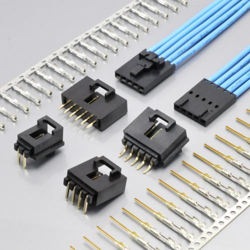
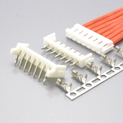
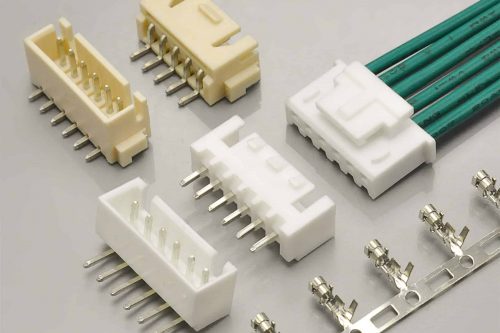
Quick answer: Molex MicroBlade is a 2.00mm pitch wire-to-board system with a friction lock and DIP (through-hole) headers, available in 2 to 15 circuits. It is rated 125V and 2.0A — but the 2.0A only applies at AWG #24. Molex publishes the rating as a four-step ladder by wire gauge: 2.0A at #24, 1.5A at #26, 1.0A at #28, and 0.5A at #30. The operating temperature range is −20°C to +85°C. The KONNRA KR2000 is the cross-reference equivalent, and it matches the original on voltage, contact resistance, insulation resistance, wire range and insulation diameter — but it publishes a single current figure, claims a wider temperature range (−40°C to +105°C) and a higher dielectric strength (800V AC/minute against Molex’s 500V AC/1 minute). And the most important fact on this page is not in the specification table at all: Molex’s MicroBlade housings and terminals are marked “Not Recommended For New Design”, and both header series are “Obsolete”.
That last point is worth stating before anything else, because it changes what a cross-reference question is even asking.
If you are designing MicroBlade into a new product today, you are designing in a system that Molex has already begun retiring. If you are maintaining a product that already uses it, you are holding a bill of materials that will eventually need a change. In both cases the useful question is not “does an equivalent exist” but “what are my options, and what does each one cost me in re-qualification?” This guide answers that question with the published documents from both manufacturers, and it flags every figure where the two sides disagree.
Every number below is traceable to a source listed in the final section. Where a figure is not published anywhere we could verify, we say so rather than filling the gap.
At a glance — Molex MicroBlade vs the KONNRA KR2000
| Parameter | Molex MicroBlade (51004 / 50011 / 53014 / 53015) | KONNRA KR2000 | Status |
|---|---|---|---|
| Pitch | 2.00mm | 2.00mm | Match |
| Circuits | 2 to 15 | 2 to 15 | Match |
| Architecture | Wire-to-board, friction lock, DIP header | Wire-to-board, DIP wafer | Match |
| Mating height | 5.80mm (housing) | not stated | — |
| Rated voltage | 125V | 125V AC/DC | Match |
| Rated current | 2.0A @ #24 · 1.5A @ #26 · 1.0A @ #28 · 0.5A @ #30 | 2A (24AWG) — single figure | Differs in presentation |
| Operating temperature | −20°C to +85°C | −40°C to +105°C | Differs |
| Contact resistance | 20mΩ max | 20mΩ max | Match |
| Insulation resistance | 1000MΩ min | 1000MΩ min | Match |
| Dielectric withstanding | 500V AC / 1 minute | 800V AC / minute | Differs |
| Wire range | AWG 24–30 | AWG 24–30 | Match |
| Wire insulation O.D. | 0.80–1.40mm | 1.4mm max | Match |
| Durability | 30 mating cycles | 30 cycles | Match |
| Housing material | Glass-filled 6/6 nylon, UL 94V-0 | PA66, UL94 V-0 | Close |
| Wafer/header contact | Phosphor Bronze | Brass (wafer contact) · Phosphor bronze (terminal) | Differs on the wafer |
| Plating | Tin (mating and termination) | Tin plated over nickel | KONNRA adds a nickel barrier |
| PCB thickness (recommended) | 1.60mm | not stated | — |
| PC tail length | 3.50mm | not stated | — |
| Board retention feature | PCB retention: yes | Solder tab: none | Verify |
| Lock to mating part | Yes (friction lock, locking windows) | not stated | — |
| UL / CSA | UL E29179 · CSA LR19980 | not stated | — |
| Lifecycle status | Housing NRND · Terminal NRND · Headers Obsolete | in production | The main point |

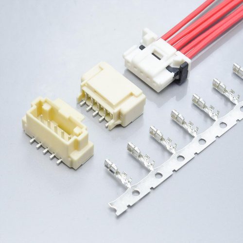
KR2000 — KONNRA’s MicroBlade 2.00mm equivalent
Read the three “Differs” rows and the lifecycle row before you go any further. They are the whole decision.
The 2A headline is really a four-step ladder, and the bottom step is 0.5A
Molex does not publish a single current rating for MicroBlade. It publishes a table:
| Wire gauge | AWG #24 | AWG #26 | AWG #28 | AWG #30–34 |
|---|---|---|---|---|
| Current | 2.0A | 1.5A | 1.0A | 0.5A |
Read that as a sequence rather than as values, because the shape is the point. The current rating falls by a factor of four between the largest and smallest wire this connector accepts. The 2.0A that appears in headline specifications belongs to AWG #24 and to nothing else.
This is the same structural trap that appears across small wire-to-board connectors, and it is worth being blunt about why. The rating is limited by the wire, not by the connector. A 2.00mm contact pair with a decent spring and a 20mΩ contact resistance will happily carry more current than these figures, but the wire attached to it will not — and since the wire is the customer’s, Molex can only publish a rating against a specified conductor. On a 24 AWG conductor, 2.0A is a reasonable limit. On a 30 AWG conductor, the conductor itself becomes the fuse.
Here is how the KONNRA KR2000 presents the same parameter:
| Source | Published current |
|---|---|
| KR2000 product page, specification table | 2A |
| KR2000 engineering drawing, SPECIFICATIONS block | 2A AC, DC |
| KR2000 product specification PS-KR2000-01 §4.0 | 2A (24AWG) AC/DC |
Only the product specification carries the wire gauge qualifier. The web page and the engineering drawing both state a bare “2A”.
To KONNRA’s credit, the figure is not wrong, and its formal specification does attach the gauge — the manufacturer published the parameter honestly at the point where engineering documents are read. But the number a buyer sees first is the unqualified one, and on this series the qualification is worth a factor of four.
What the ladder means for a substitution
If your design runs MicroBlade at AWG #24, the KR2000’s 2A and your existing design agree, and the substitution changes nothing electrically. If your design runs at AWG #28 or #30, you are operating at 1.0A or 0.5A in the original system, and you should be carrying those figures through to the replacement rather than the 2A headline.
There is also a design consequence that runs the other way — and it is the useful half of this section. Because the rating is wire-limited, an application that needs more current can often be fixed with a larger wire rather than a different connector. Moving from AWG #28 to AWG #26 takes the same 2.00mm connector from 1.0A to 1.5A. Moving to AWG #24 takes it to 2.0A. If a design is bumping against the limit, check the wire first — the connector may already be capable of what you need.
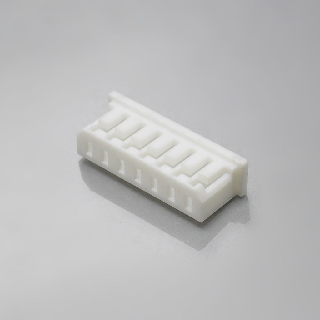
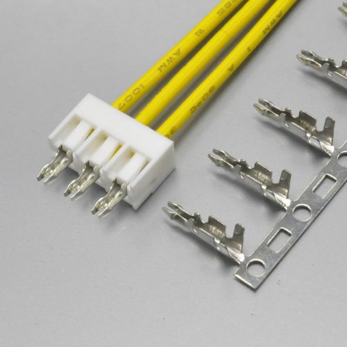
KR2000 housing — KONNRA’s MicroBlade 2.00mm equivalent
What the wire range looks like on both sides
The two manufacturers agree on the wire range itself, which is unusual enough to be worth stating plainly:
| Molex | KONNRA KR2000 | |
|---|---|---|
| Applicable wire | AWG 24, 26, 28, 30 | AWG 24# ~ 30# |
| Insulation O.D. | 0.80–1.40mm | 1.4mm max |
| Current ladder | 2.0 / 1.5 / 1.0 / 0.5A | single figure, 2A at AWG #24 |
| Crimp pull-out force | not published on the MicroBlade datasheet | 3.63 / 2.27 / 1.36 / 0.9 kgf min for 24 / 26 / 28 / 30 AWG |
Two notes on that table.
KONNRA publishes the crimp pull-strength requirement and Molex’s MicroBlade datasheet does not. That is a case where the cross-reference supplier has the more complete document. If you are writing an incoming-inspection procedure for a MicroBlade-compatible crimp, the per-gauge minimum pull figures you need are already published by KONNRA — and they fall from 3.63 kgf at AWG #24 to 0.9 kgf at AWG #30, a factor of four, which is the crimp-side echo of the current ladder.
KONNRA states only the maximum insulation diameter (1.4mm); Molex states a window (0.80–1.40mm). A wire with insulation thinner than 0.80mm is inside Molex’s published window and outside KONNRA’s published window. That is the same class of gap we have flagged on other series, and it matters because the insulation crimp height is set against the insulation diameter. If your wire is a thin-wall construction below 0.80mm, confirm it before you commit.
The temperature range: Molex says −20°C to +85°C, KONNRA says −40°C to +105°C
This is the largest single discrepancy between the two data sets, and unlike the current rating it is not a matter of presentation.
Molex publishes −20°C to +85°C for MicroBlade in three separate places:
| Molex source | Operating temperature |
|---|---|
| 53014 / 53015 header datasheet, Physical section | −20 to +85°C |
| 51004 housing product page, Physical section | −20° to +85°C |
| 53014 header part detail page | −20° to +85°C |
Three independent Molex documents, one figure. That is about as firm as a published parameter gets.
KONNRA publishes −40°C to +105°C:
| KONNRA source | Temperature range |
|---|---|
| KR2000 product specification PS-KR2000-01 §4.0 | −40°C ~ +105°C |
| KR2000 engineering drawing (housing, terminal, both wafers) | −40°C ~ +105°C |
| KR2000 product page, specification table | −40°C ~ +105°C |
KONNRA’s lower limit is 20°C lower and its upper limit is 20°C higher. Both extensions are in the direction a designer wants, which is exactly why they deserve scrutiny rather than a nod.
KONNRA’s numbers are backed by its own test programme
Unlike some claims we have audited, these are not free-floating. The same specification that publishes the range also publishes the environmental tests that establish it:
| Test | Condition | Requirement |
|---|---|---|
| Heat resistance (§7.5) | 105 ± 2°C, 96 hours (EIA-364-17B) | No damage; contact resistance 40mΩ max |
| Cold resistance (§7.6) | −40 ± 2°C, 96 hours (EIA-364-59) | No damage; contact resistance 40mΩ max |
| Thermal shock (§7.8) | −40°C 30 min → room temp 5 min → +105°C 30 min → room temp 5 min = 1 cycle, 5 cycles (EIA-364-32B) | No damage; contact resistance 40mΩ max |
The rated extremes are the tested extremes. That is the right way round, and it means the KR2000 has documented evidence at −40°C and at +105°C that the MicroBlade datasheet does not publish at its own limits.
So which number do you design to?
There are three legitimate answers, and which one is right depends on why you are asking.
If you are replacing a MicroBlade part in an existing product that was designed to Molex’s published range, the original design’s thermal margin is 85°C at the top and −20°C at the bottom. The KR2000’s wider range is a potential improvement, not a requirement — and switching to it does not invalidate the existing design basis unless you want it to.
If your application genuinely needs to operate below −20°C or above +85°C, then the original MicroBlade is outside its published operating range and the KR2000’s range becomes the more relevant document. This is one of the few cases where a cross-reference part may be better than the original rather than merely equivalent — and it is worth verifying rather than assuming, because the KR2000’s numbers are the supplier’s own test results, not a third-party certification.
If you need to qualify the replacement to your own thermal requirement, ask for the raw test report behind §7.5, §7.6 and §7.8 rather than the summary table. A specification that publishes its test standards (EIA-364-17B, −59, −32B) is a specification whose underlying data can be requested.
One caution that applies to both parts. The +105°C figure is the connector’s own capability. It says nothing about the wire insulation you crimp into it, or about the solder joint’s thermal cycling behaviour on your board. On a DIP through-hole part, the connector and the board share a thermal path, and a board-level temperature problem will not be fixed by a wider connector rating.
The lifecycle question: this system is being retired
This section is the reason this guide is worth reading even if you never buy a KR2000, because it is the fact most likely to change a design decision — and it is invisible in every specification table on the page.
Molex has published lifecycle notices on the entire MicroBlade 2.00mm system.
| Molex part | Series | Status | Replacement |
|---|---|---|---|
| Housing | 51004 | Not Recommended For New Design | 510650800 |
| Crimp terminal | 50011 | Not Recommended For New Design | 502128000 |
| Header, vertical | 53014 | Obsolete | 532530370 |
| Header, right angle | 53015 | Obsolete | 532540270 |
The headers carry Product Change Notifications in Molex’s own record: PCN 509450, issued 2020-09-21, and PCN 509547, issued 2020-10-16 — both with an implementation date of 2021-09-21, both with the stated change reason “OBS – Obsolete”, and both carrying the standard notice that the referenced parts “will be made obsolete.”
So the headers have been obsolete since 2021, and the housing and terminal are flagged as not recommended for new designs. A designer specifying MicroBlade in 2026 is specifying a system that has been on its way out for five years.
The migration is not a drop-in, and Molex says so explicitly
Here is the sentence that matters, published verbatim on the Molex part pages for both the housing and the terminal:
“Replacement part is not a drop in replacement. All of related parts, crimp terminal/50011, housing/51004 and header/53014 & 53015 need to be replaced to Micro-Latch series (
undefined/terminal,undefined/housing,undefined/ST hdr andundefined/RA hdr).”
Read what that commits you to. Molex’s own migration path changes three parts at once — terminal, housing and header — from MicroBlade to a different series, Micro-Latch. Every one of those three parts has to be re-sourced, re-tooled and re-qualified, and because Micro-Latch is a different product family, the PCB footprint has to be reviewed too. Molex’s own part pages describe the replacements as having different size and different mating parts.
That is the real cost of the obsolescence. It is not “find a new housing” — it is a harness redesign plus a board revision plus a re-qualification cycle.
Which is where a cross-reference part earns its place
If you must touch all three parts anyway, the comparison is no longer “MicroBlade versus its replacement” — it is between the available options, evaluated on their own merits. And that is a fairer comparison for the KR2000 than a straight drop-in claim would be, because the KR2000:
- keeps the 2.00mm pitch and the 2-to-15 circuit range,
- keeps the DIP through-hole header architecture,
- matches the original on 125V, 20mΩ contact resistance, 1000MΩ insulation resistance, AWG 24–30 and 0.80–1.40mm insulation,
- matches the original on 30-cycle durability,
- and avoids the second supplier-family change that a move to Micro-Latch would require.
What we are not claiming: that the KR2000 is a drop-in replacement for MicroBlade. It is not, and nobody should treat it as one until the footprint has been compared. The pin pattern and the mechanical envelope have to be checked against Molex’s sales drawings for the 51004 housing and the undefined / undefined headers — and if your board is already released, that comparison is the first thing to do, not the last. Our published dimensions for the wafer (2 circuits: A = 2.00mm, B = 6.00mm) and the housing (2 circuits: A = 2.00mm, B = 4.90mm) are in the engineering drawing linked at the end of this guide; put them next to Molex’s drawing for your part number and the answer will be unambiguous.
One more thing to check on any existing design, and this one is easy to miss: KONNRA’s specification states “Solder tab: None” for both the 180° and 90° wafers, while Molex’s part data for the 53014 header lists “PCB retention: yes”. If the original design relies on a board-retention feature — an interference post, a locking peg, a solder nail — then that difference matters mechanically, and it needs to be reconciled explicitly rather than assumed away. If your board is fixed only by the through-hole solder joints, then both parts are in the same situation and the comparison is straightforward.

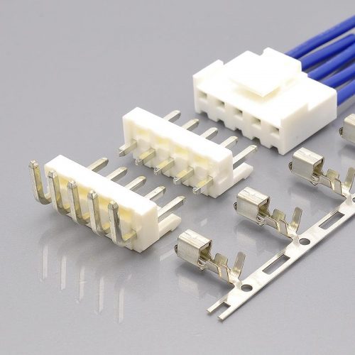
KR2000 DIP 180° straight wafer
What MicroBlade is, mechanically
Setting the lifecycle question aside, here is the system as a piece of engineering.
It is a DIP (through-hole) wire-to-board connector, not an SMT one. The header solders into plated through-holes with a PC tail length of 3.50mm, and Molex recommends a PCB thickness of 1.60mm. That is the single biggest architectural difference between this series and the 1.5mm connectors it superficially resembles — and it decides your assembly process before any electrical parameter does.

KR2000 — DIP through-hole MicroBlade equivalent
It uses a friction lock, not a positive latch. Molex describes the housing as “Friction Lock, 5.80mm Height” and the header datasheet says “Locking windows provide secure mating.” So retention comes from a mechanical engagement between features on the housing and windows on the header, engaged by pushing the connector home. It is a real lock — it has to be released deliberately to separate the parts — but it is not the same mechanism as the audible-click inner positive lock used on CLIK-Mate 1.5, and it should not be treated as interchangeable in a specification.
The header is shrouded. Molex’s part data records the 53014 as “Shrouded”, which means the contacts sit inside a walled housing rather than standing as bare pins. Practically, that protects the contacts during handling and makes the connector harder to mis-align on insertion — and it also means the connector’s insertion envelope is larger than the pin field alone.
It is a single-row system. One row, 2 to 15 circuits, and the header is not stackable and not breakaway per Molex’s part data. You order the circuit count you need.
Its mating height is 5.80mm. That is stated on the housing description and is the dimension to check against your enclosure clearance.
And the plating is tin, on both the mating and the termination side. Molex’s 53014 part data lists tin for both. KONNRA’s KR2000 is tin plated over nickel, which adds a nickel diffusion barrier under the tin. That is a common and sensible construction for a part expected to see thermal cycling; it is not a like-for-like plating description on a specification sheet, so if your qualification document names the plating system, this is a line to update rather than to copy across.
One documentation quirk worth knowing before you search for parts
Molex’s product page describes the undefined crimp terminal as “2.00mm Pitch MicroBlade Wire-to-Wire Crimp Terminal, Female, 30-24 AWG, Reel” — while the housing it goes into, 51004, is described as a “Wire-to-Board Housing”, and the header datasheet lists the 53014 / 53015 as “Wire-to-Board” headers that mate with 51004.
The terminal description says wire-to-wire; everything else in the system says wire-to-board. Since the 50011 terminal is the part that crimps to the wire and inserts into the 51004 housing that plugs onto the 53014 / 53015 header, the system is unambiguously wire-to-board, and the “wire-to-wire” wording in that one product description appears to be a copy error in Molex’s own catalogue copy.
It is worth knowing because it affects searching. If you are looking for the terminal and filtering by category, a “wire-to-wire” label in the result can make you think you have found the wrong part. You have not. Confirm by the series number undefined and by the fact that it mates with undefined, not by the category label.
How to identify whether your connector is MicroBlade
The 2.00mm pitch class is one of the most crowded in connector design — KONNRA’s own 2.00mm index lists more than a dozen series in this pitch — and several of them share the same footprint philosophy. Work through these in order; the first two questions do most of the work.
1. Is it through-hole or surface-mount? MicroBlade headers are DIP through-hole parts with a 3.50mm PC tail, recommended for 1.60mm boards. If the header is soldered to pads on the board surface, it is not MicroBlade — and in the 2.00mm class you are then looking at one of the SMT families. This single question eliminates most of the field.
2. Does the lock engage on the housing, with visible windows in the header walls? MicroBlade is a friction lock system, and the header datasheet describes it in four words: “Locking windows provide secure mating.” Look at the header’s shroud. If you can see cut-outs or windows in the shroud wall that a feature on the mating housing clicks into, you are in the friction-lock group. This distinguishes it from a plain friction-only connector (no engagement feature at all) and from a side-latch design (where the latch sits on the outside of the housing rather than in a window).
3. Is the header shrouded? Molex’s part data records the 53014 as “Shrouded” — the contacts are enclosed by walls, not standing free. A bare pin field in 2.00mm is a different family.
4. Measure the mating height. MicroBlade’s housing is described as 5.80mm height. Measure from the board surface to the top of the mated assembly and compare. On a 2.00mm DIP system, height is often the parameter that decides an enclosure fit.
5. Count positions and rows. MicroBlade is single row, 2 to 15 circuits. An odd-count dual-row 2.00mm connector is not this family. If you count 2×N, you are looking at something like JST PHD (KONNRA KR2005, 2×2 to 2×20) or a dual-row pin header instead.
6. Check for the board-retention question. If the header has posts, pegs or solder nails that pass through the board besides the contacts, that is a retention feature — and it is a difference worth noting, because KONNRA’s KR2000 specification states “Solder tab: None” for its wafers while Molex’s 53014 part data lists “PCB retention: yes”. Whether this matters depends entirely on whether your design relies on it.
7. Read the part numbers, then convert them. Molex’s MicroBlade numbers group by function — undefined for the housing, undefined for the crimp terminal, undefined for the vertical header, undefined for the right-angle header (with undefined also listed as a mating header on the housing page). KONNRA’s equivalents use an undefined housing prefix, undefined for the terminal, and undefined / undefined for the 180° and 90° wafers.
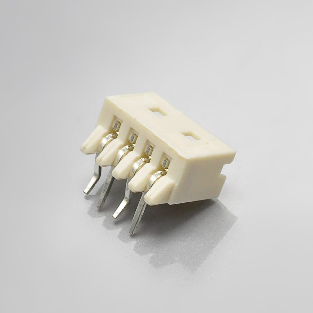
KR2000 DIP 90° right-angle wafer
Where MicroBlade sits in the 2.00mm class
The most common mistake with this pitch is assuming that any 2.00mm connector can substitute for any other. The class spans a 2.5× range in current and a 2.5× range in voltage, and the architectures are not interchangeable.
The table below uses KONNRA’s own published 2.00mm index for the cross-reference entries, so the positioning is the supplier’s own:
| KONNRA series | Cross-references to | Architecture | Current | Voltage | Circuits |
|---|---|---|---|---|---|
| KR2000 | Molex MicroBlade mx2.0 | DIP, wire-to-board | 2A | 125V | 2–15 |
| KR2001 | JST PH 2.0 | Wire-to-board | 2A | 100V | 2–16 |
| KR2002 | IL-S | Wire-to-board | 2A | 100V | 2–16 |
| KR2003 | JST SAN / SJN 2.0 | Board-in | 2A | 250V | 2–16 |
| KR2004 | Yeonho YH200 / PH 2.0 | Wire-to-board | 2A | 250V | 2–16 |
| KR2005 | JST PHD 2.0 | Wire-to-board, 2 rows | 3A | 250V | 2*2–2*20 |
| KR2009 | Hirose DF3 | Wire-to-board | 3A | 250V | 2–15 |
| KR2014 | JST PA 2.0 | Wire-to-board | 3A | 250V | 2–15 |
| KR2017 | Molex DuraClik mx2.0 | Wire-to-board | 3A | 125V | 2–14 |
| KR2021 | Molex MINI50 | Wire-to-board, 3 rows | 4A | 250V | 34 |
| KR2023 | JST ULH 2.0 | Wire-to-board | 5A | 100V | 2–10 |
Three observations worth carrying into a design review.
MicroBlade is at the low end of the class on both current and voltage. At 2A and 125V it sits below the 3A / 250V block that most of this table occupies, and well below the 5A entry. That is not a criticism of the connector — 2A at 125V is a perfectly good signal-and-small-power rating — but it does mean that if your project’s requirement creeps upward, the connector is the piece that will run out of margin first, and the replacement will involve a footprint change because none of the higher-rated entries share its DIP architecture.
Only two entries in the class are not wire-to-board with an SMT wafer. The KR2003 (board-in, no wafer at all) and the KR2000 itself (DIP through-hole). If your assembly process is through-hole, you are choosing from a much shorter list than the table suggests.
Only one entry is dual-row or multi-row in a way that could be confused with a single-row part. The KR2005 (2*2–2*20) and KR2021 (three rows, 34 positions) are the high-density options, and their position counts are the ones people mis-read as single-row counts when skimming. Check the row count before comparing circuit numbers.
And a note on the voltage figures in this table. The 250V values that dominate it are rated voltages, not dielectric withstanding values, and the two are not interchangeable. On this series, Molex publishes a 125V rated voltage alongside a 500V AC/1-minute dielectric withstanding voltage — a 4× relationship. When you compare across the table, compare like with like: a 250V rated voltage is not comparable to a withstanding figure, and a withstanding figure tells you nothing about continuous working voltage.
The full electrical and environmental comparison
Everything both sides publish, side by side. Where a parameter is published by only one supplier, that is stated rather than left blank.
Ratings
| Item | Molex MicroBlade | KONNRA KR2000 | Status |
|---|---|---|---|
| Rated voltage | 125V | 125V AC/DC | Match |
| Rated current | 2.0A @ #24 · 1.5A @ #26 · 1.0A @ #28 · 0.5A @ #30 | 2A @ AWG #24 | Ladder not published by KONNRA |
| Operating temperature | −20 to +85°C | −40 to +105°C | Differs |
| Applicable wire | AWG 24, 26, 28, 30 | AWG 24#–30# | Match |
| Insulation O.D. | 0.80–1.40mm | 1.4mm max | Match on the maximum |
| Durability | 30 mating cycles | 30 cycles | Match |
Electrical performance
| Item | Molex MicroBlade | KONNRA KR2000 | Status |
|---|---|---|---|
| Contact resistance | 20mΩ max | 20mΩ max (EIA-364-23C, dry circuit 20mV / 100mA) | Match |
| Insulation resistance | 1000MΩ min | 1000MΩ min (EIA-364-21B, 500V DC / 1 min) | Match |
| Dielectric withstanding | 500V AC / 1 min | 800V AC / minute (EIA-364-20A) | Differs — KONNRA 60% higher |
| Temperature rise | not published on the MicroBlade datasheet | 30°C max (EIA-364-70B) | KONNRA only |
| Contact resistance after environmental exposure | not published | 40mΩ max | KONNRA only |
The withstanding voltage row is the one to handle carefully. KONNRA publishes 800V AC for one minute; Molex publishes 500V AC for one minute for the same pitch, the same 125V rating and a comparable construction. Both are written as one-minute AC proof tests with a “no breakdown” acceptance criterion, so the comparison is like-for-like and the difference is real.
A higher proof voltage is a claim of better dielectric margin, not a defect — and if the KR2000 genuinely withstands 800V AC for a minute, that is a stronger part than the original on this axis. But it is the supplier’s own tested claim, published without a third-party verification attached, and it appears alongside a temperature range and a current figure that also differ from the original. If your design or your production test relies on a specific proof voltage, ask for the test report rather than adopting the higher number.
Mechanical performance
| Item | Molex MicroBlade | KONNRA KR2000 |
|---|---|---|
| Terminal insertion force | not published on the MicroBlade datasheet | 1.0 kgf (9.8N) max |
| Terminal / housing retention | not published | 1.0 kgf (9.8N) min |
| Pin retention in the wafer | not published | 1.0 kgf (9.8N) min |
| Crimp pull strength | not published | 3.63 / 2.27 / 1.36 / 0.9 kgf min (24 / 26 / 28 / 30 AWG) |
| PC tail length | 3.50mm | not stated |
| Recommended PCB thickness | 1.60mm | not stated |
| Mating height | 5.80mm | not stated |
| Shrouded | Yes | not stated |
| Board retention feature | PCB retention: yes | Solder tab: none |
On the mechanical side the two data sets barely overlap, which is worth understanding rather than reading as a gap. Molex publishes the board-side geometry — tail length, board thickness, mating height, shroud — because those are the dimensions a designer needs to lay out a footprint. KONNRA publishes the assembly-side forces — insertion, retention, crimp strength — because those are the numbers a harness builder and an incoming-inspection procedure need.
So the two documents answer different questions, and you need both. A complete qualification file for a KR2000 substitution should contain Molex’s sales drawing for the footprint (tail length and board thickness are the two that will bite) plus KONNRA’s force table and crimp specification (which Molex does not publish for this series at all).
Environmental performance
| Item | Molex MicroBlade | KONNRA KR2000 |
|---|---|---|
| Durability | 30 cycles | 30 cycles, contact resistance ≤40mΩ after |
| Temperature rise | not published | 30°C max |
| Vibration | not published on the datasheet | 1.5mm P-P, 10→55→10 Hz in 1 min, 2 hours per axis (EIA-364-28B) → discontinuity ≤1 microsecond |
| Mechanical shock | not published | 490 m/s² (50G), 3 strokes in each of 6 directions (EIA-364-27B) |
| Heat resistance | not published | 105 ± 2°C, 96 hours (EIA-364-17B) |
| Cold resistance | not published | −40 ± 2°C, 96 hours (EIA-364-59) |
| Thermal shock | not published | 5 cycles (EIA-364-32B) |
| Humidity | not published | 40 ± 2°C, 90–95% RH, 96 hours (EIA-364-31B) → 40mΩ max, must meet the dielectric test, insulation resistance 100MΩ min |
| Salt spray | not published | 24 hours, 35 ± 2°C, 5 ± 1% NaCl (EIA-364-26B) |
| Solderability | not published | 245 ± 5°C, 3 ± 0.5 s, ≥95% of immersed area (EIA-364-52) |
| Solder heat resistance | not published | DIP profile, 250°C max peak, 3–5 seconds (EIA-364-71B) |
Note the humidity line specifically, because it is a case where a relaxed figure is easy to misread. KONNRA’s §7.7 requires 40mΩ max contact resistance, no dielectric breakdown, and 100MΩ minimum insulation resistance after 96 hours at 90–95% RH. That 100MΩ is a post-humidity allowance, not the part’s insulation resistance — which remains 1000MΩ minimum under §5.2, and which matches Molex. Do not carry 100MΩ into a specification as the part’s rating.
And note what the vibration test actually proves. KONNRA requires interruption of no more than 1 microsecond during two hours per axis at 1.5mm peak-to-peak. That is a genuine electrical-continuity criterion under excitation — the same class of requirement as on the 1.5mm series we have documented — and it is the mechanical justification for a friction lock with locking windows rather than a plain friction fit.
The force table: two linear rules and a retention loss that hits small connectors hardest
KONNRA publishes a complete insertion and withdrawal force table for the KR2000 across the whole 2-to-15 circuit range, both as new and after the rated 30 cycles. Molex’s MicroBlade datasheet does not publish one — those figures live in the product specification PS-51004-002, which was not retrievable in text form for this review — so this is a case where the cross-reference supplier’s published data goes further than the original’s.
That makes the table worth reading in its own right, because it is a complete specification rather than a sample of one.
| Circuits | Insertion force (max) | Withdrawal force (min), initial | Withdrawal force (min), after 30 cycles |
|---|---|---|---|
| 2 | 3.60 | 0.46 | 0.36 |
| 3 | 4.40 | 0.55 | 0.45 |
| 4 | 5.20 | 0.70 | 0.60 |
| 5 | 6.00 | 0.80 | 0.70 |
| 6 | 6.60 | 0.90 | 0.80 |
| 7 | 7.20 | 1.00 | 0.90 |
| 8 | 7.80 | 1.10 | 1.00 |
| 9 | 8.40 | 1.20 | 1.10 |
| 10 | 9.00 | 1.30 | 1.20 |
| 11 | 9.60 | 1.40 | 1.30 |
| 12 | 10.20 | 1.50 | 1.40 |
| 13 | 10.80 | 1.60 | 1.50 |
| 14 | 11.40 | 1.70 | 1.60 |
| 15 | 12.00 | 1.80 | 1.70 |
(All values in kgf. Molex’s equivalents are 9.8N per kgf.)
The insertion force is two straight lines, not one
Look at the increments rather than the values:
- From 2 to 5 circuits the insertion force rises by 0.80 kgf per circuit — 3.60, 4.40, 5.20, 6.00.
- From 5 to 15 circuits it rises by exactly 0.60 kgf per circuit — 6.00, 6.60, 7.20 … up to 12.00.
So the specification is two linear segments that meet at 5 circuits. Below that point each added circuit costs 0.80 kgf; above it, 0.60 kgf.
That kink is a design decision rather than an artefact, and it tells you something about the connector: the first few positions carry a disproportionate share of the relative insertion effort, which is consistent with a fixed contribution — the housing-to-header engagement itself — being amortised over more positions as the connector gets longer. On a 2-position connector, adding one circuit raises the insertion force by 22%. On a 15-position connector, adding one circuit raises it by 5%.
The practical number is the top of the table: a 15-circuit KR2000 requires up to 12.00 kgf (118N) to insert. That is a two-handed, deliberate operation, and if your assembly line uses a 15-position part it is worth treating the mating step as a process step with a fixture rather than an operator action.
The withdrawal force follows one rule — and the 30-cycle loss is a fixed 0.10 kgf
The withdrawal figures are cleaner still:
- From 4 circuits upward, the initial withdrawal force rises by exactly 0.10 kgf per circuit — 0.70 at 4 positions, 1.80 at 15, and every step in between.
- The 2- and 3-position values (0.46 and 0.55) sit slightly below that line, which would predict 0.50 and 0.60. Those are the two smallest connectors and the only two rows in the table that do not fit the pattern.
And then the finding that is genuinely worth putting in a specification review:
The post-30-cycle withdrawal force is exactly 0.10 kgf lower than the initial value at every single position count in the table — 0.46 → 0.36, 0.55 → 0.45, 0.70 → 0.60, all the way to 1.80 → 1.70. Not approximately. Exactly, at all fourteen positions.
That means the retention the connector loses over its rated life is a fixed absolute amount, not a proportional one — and so the relative loss depends entirely on how many positions you have:
| Circuits | Initial withdrawal | After 30 cycles | Retention lost |
|---|---|---|---|
| 2 | 0.46 kgf | 0.36 kgf | −21.7% |
| 3 | 0.55 kgf | 0.45 kgf | −18.2% |
| 4 | 0.70 kgf | 0.60 kgf | −14.3% |
| 8 | 1.10 kgf | 1.00 kgf | −9.1% |
| 15 | 1.80 kgf | 1.70 kgf | −5.6% |
A 2-position KR2000 loses more than a fifth of its withdrawal force across the rated 30 cycles. A 15-position part loses 5.6%. The absolute loss is identical in both cases — 0.10 kgf — but the small connector has far less retention to start with.
This is worth knowing because small connectors are exactly where people assume retention is a non-issue. A 2-position connector on a short harness feels trivial to specify. But if that harness is handled, dressed or flexed in service, the retention margin at cycle 30 is a fifth smaller than the figure on the datasheet, and the datasheet figure was already the minimum for a new part.
What to do with it: for low-position-count designs, treat the initial withdrawal figure as a beginning-of-life number and specify against the 30th-cycle value if the connector will see repeated mating. And note that KONNRA’s durability test (§7.1) is the test that establishes this: 30 cycles at a rate not exceeding 10 cycles per minute, with contact resistance required to remain at or below 40mΩ afterwards — double the 20mΩ initial limit.
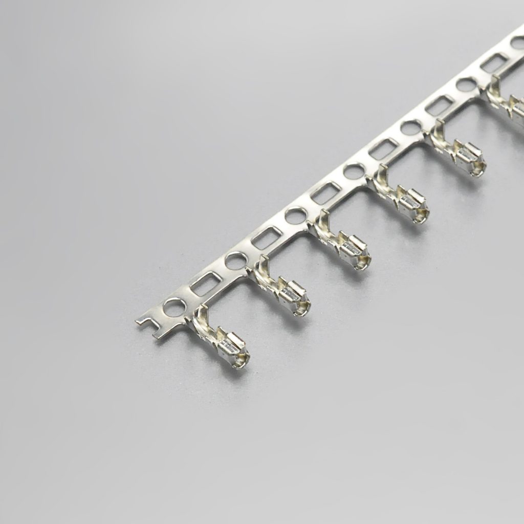
KR2000 terminal — KONNRA part T20000PT0101A
Crimp and tooling
One terminal serves the whole series, so there is a single crimp specification for 2 through 15 circuits — and it is unusually specific, with a column for each wire gauge in the range:
| Crimp parameter | 24 AWG | 26 AWG | 28 AWG | 30 AWG |
|---|---|---|---|---|
| Crimp width (conductor, ①) | 1.05 ± 0.05 | 1.05 ± 0.05 | 1.05 ± 0.05 | 1.05 ± 0.05 |
| Crimp height (conductor, ①) | 0.75 ± 0.05 | 0.70 ± 0.05 | 0.65 ± 0.05 | 0.60 ± 0.05 |
| Crimp width (insulation, ②) | 1.20 ± 0.05 | 1.20 ± 0.05 | 1.20 ± 0.05 | 1.20 ± 0.05 |
| Crimp height (insulation, ②) | 1.55 ± 0.05 | 1.45 ± 0.05 | 1.35 ± 0.05 | 1.35 ± 0.05 |
| Crimp strength | 3.63 kgf min | 2.27 kgf min | 1.36 kgf min | 0.9 kgf min |
| Stripping length | 1.3–1.8mm | 1.3–1.8mm | 1.3–1.8mm | 1.3–1.8mm |
| Terminal quantity | 10,000 pcs per reel |
Three things in that table are worth pulling out.
The conductor crimp height window is 0.10mm wide at every gauge, and it drops by 0.05mm per wire step. 0.75, 0.70, 0.65, 0.60 — a clean geometric progression, each value ±0.05mm. A crimp height window of ±0.05mm on a 0.6mm target is a tight process, and it is the reason the applicator setup is worth verifying by measurement rather than by visual inspection. A crimp that looks closed can still be 0.08mm off nominal.
The crimp strength falls by a factor of four across the wire range — 3.63 kgf at AWG #24 down to 0.9 kgf at AWG #30. That is the crimp-side mirror of the current ladder: same four-to-one ratio, same direction. If you build mixed-gauge harnesses into one housing, your pull-test acceptance criterion differs per circuit, and a single pass/fail figure will either pass bad crimps at 24 AWG or reject good ones at 30 AWG.
28 and 30 AWG share the same insulation crimp height (1.35mm) while their conductor crimp heights differ (0.65 and 0.60). So the insulation crimp does not step with every wire gauge — it steps every other one. Worth knowing if your tooling setup procedure assumes one adjustment per gauge.
Tooling
Molex packages the 50011 terminal on reel, and the terminal’s part data records a wire insulation diameter of 0.80–1.40mm that matches KONNRA’s published 1.4mm maximum. Neither manufacturer’s published material reviewed here names a specific applicator or die set for this terminal, so the tooling has to be matched to the crimp table rather than to a named die — which means the crimp table above is your acceptance document, and measuring to it is what proves the setup.
And one measurement note that matters more here than on most connectors. Because the current rating is wire-limited (the 0.5A at AWG #30), the crimp is carrying a larger share of the electrical responsibility than usual. A crimp that closes on insulation instead of conductor will pass a continuity check and still fail in service — and on this series the conductor crimp height window is only ±0.05mm. Measure it.
DIP process and board layout
This is a through-hole part, so the process questions are different from an SMT family — and they start before the soldering step.
Board geometry
Molex publishes the two numbers that decide whether your board can accept the header:
- PC tail length: 3.50mm
- Recommended PCB thickness: 1.60mm
Those are on the 53014 part data and they are the first thing to check against an existing board. A 3.50mm tail is designed to pass through and protrude below a board in the 1.6mm class; if your board stack is thicker, the tail is shorter below the board than the design intends, and if it is thinner the tail is longer. Neither is automatically a problem, but both change the soldering process, and one of them changes the mechanical clearance under the board.
Soldering profile
KONNRA publishes a wave soldering profile for the DIP version (§9.0), referenced from the solder-heat-resistance test in §7.11:
| Parameter | Value |
|---|---|
| Peak temperature | 250°C max, for 3–5 seconds |
| Time at minimum 217°C | 60–150 seconds |
| Pre-heat | 150–180°C |
The source drawing also carries a 60–180 s band and a 30 s annotation in the same profile diagram, so if your process window is tight, read the profile off the PDF rather than from this summary — the diagram resolves the bands, and which one applies depends on your board.
Molex does not publish a soldering profile on the MicroBlade datasheet. So on the process side the KR2000 also has the more complete published document — with the important caveat that a profile from one supplier is a starting point, not a substitute for your own measurement. Both manufacturers say the same thing in different words: KONNRA’s profile carries the note “please check the reflow soldering condition by your own devices beforehand. Because the condition changes by the soldering devices, P.C. boards, and so on.”
Footprint dimensions
KONNRA publishes the housing and wafer dimension tables in full, and the pattern is clean:
| Circuits | Housing A | Housing B | Wafer A | Wafer B |
|---|---|---|---|---|
| 2 | 2.00 | 4.90 | 2.00 | 6.00 |
| 3 | 4.00 | 6.90 | 4.00 | 8.00 |
| 4 | 6.00 | 8.90 | 6.00 | 10.00 |
| 5 | 8.00 | 10.90 | 8.00 | 12.00 |
| 10 | 18.00 | 20.90 | 18.00 | 22.00 |
| 15 | 28.00 | 30.90 | 28.00 | 32.00 |
Both dimensions advance by exactly 2.00mm per circuit — the pitch — in both the housing and the wafer table. There are no exceptions, and the general tolerance block is X.X ±0.30 · X.XX ±0.20 · X.XXX ±0.10 · angle ±2°.
One detail that is genuinely convenient: the 90° and 180° wafers share an identical A and B dimension table. The straight (C2000VD) and right-angle (C2000RD) wafers both run A from 2.00 to 28.00 and B from 6.00 to 32.00 across the 2–15 circuit range. So the board footprint is the same for both orientations — the choice between them is about which way the wire leaves the board, not about the pattern you drill. That is worth knowing early in a layout, because it means you can defer the orientation decision without holding up the board.
And the one to flag for review. KONNRA’s specification states “Solder tab: None” for both the 180° and the 90° wafer. There is no solder nail, no interference post and no board-locking peg in the KR2000 wafer — the wafer is held by its contact tails alone. Molex’s 53014 part data lists “PCB retention: yes” for the original header. If your design, your drop test or your mechanical qualification relies on a retention feature beyond the solder joints, that is a difference to resolve explicitly — and it is the one item in this comparison that a footprint drawing check will not catch.
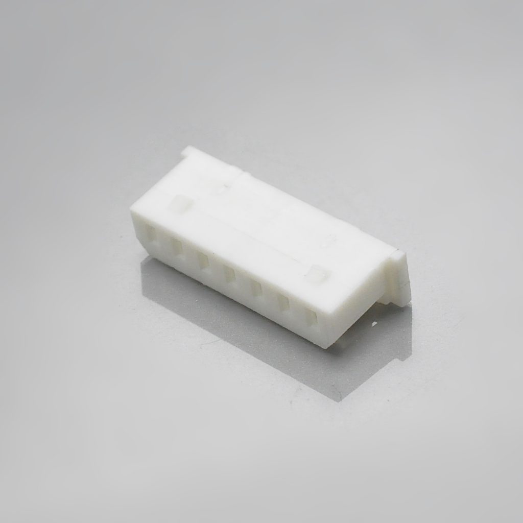
KR2000 2.00mm pitch housing
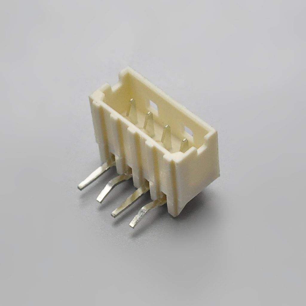
KR2000 right-angle wafer
Decoding the part numbers, and the full cross-reference
Because both manufacturers encode the circuit count inside the part number, this series is unusually easy to convert once you know the pattern — and unusually easy to get wrong when you transcribe it by hand.
The pattern
In the pattern column below, NN stands for the circuit count. Everything else in the string is fixed:
| Maker | Function | Part number pattern | Example (5 circuits) |
|---|---|---|---|
| Molex | Housing | 51004-0NN0 |
51004-0500 |
| Molex | Terminal | 50011-8000 |
one part for the series |
| Molex | Vertical header | 53014-0NN10 |
53014-0510 |
| Molex | Right-angle header | 53015-0NN10 |
53015-0510 |
| KONNRA | Housing | H200001NN0101A |
H200001050101A |
| KONNRA | Terminal | T20000PT0101A |
one part for the series |
| KONNRA | 180° DIP wafer | C2000VD1NN22T0101BB |
C2000VD10522T0101BB |
| KONNRA | 90° DIP wafer | C2000RD1NN22T0101BB |
C2000RD10522T0101BB |
The KONNRA circuit code is a 1NN triple — 102 for 2 circuits, 105 for 5, 115 for 15 — which the drawing’s own ordering-code note confirms: “102:2, 115:15”. Molex’s is a two-digit infix sitting in a different position of the string.
The error mode to watch for is transposition. 51004-0500 and 51004-1000 differ by one character and by five circuits; on the KONNRA side, C2000VD10522T0101BB and C2000VD11522T0101BB differ by one character and by ten. Neither mistake is visible once the parts are out of the bag. Convert by pattern, not by hand-typing.
The cross-reference, as KONNRA publishes it
KONNRA maintains a full Molex-to-KONNRA mapping for this series covering every circuit count from 2 to 15 across all three components. A representative extract:
| Molex | KONNRA | Description |
|---|---|---|
51004-0200 |
H200001020101A |
Housing 2P |
51004-0400 |
H200001040101A |
Housing 4P |
51004-0600 |
H200001060101A |
Housing 6P |
51004-0800 |
H200001080101A |
Housing 8P |
51004-1000 |
H200001100101A |
Housing 10P |
51004-1200 |
H200001120101A |
Housing 12P |
51004-1500 |
H200001150101A |
Housing 15P |
50011-8000 |
T20000PT0101A |
Terminal (all circuits) |
53014-0210 |
C2000VD10222T0101BB |
DIP 180° wafer 2P |
53014-0410 |
C2000VD10422T0101BB |
DIP 180° wafer 4P |
53014-0810 |
C2000VD10822T0101BB |
DIP 180° wafer 8P |
53014-1510 |
C2000VD11522T0101BB |
DIP 180° wafer 15P |
53015-0210 |
C2000RD10222T0101BB |
DIP 90° wafer 2P |
53015-0410 |
C2000RD10422T0101BB |
DIP 90° wafer 4P |
53015-0810 |
C2000RD10822T0101BB |
DIP 90° wafer 8P |
53015-1510 |
C2000RD11522T0101BB |
DIP 90° wafer 15P |
The verified mapping covers the complete 2-to-15 range for the housing, both wafers and the terminal — 46 entries in total. If you need a circuit count not shown above, ask for the specific pair rather than extrapolating the string; the pattern is consistent, but confirming a part number costs a day and a wrong one costs a build.
One naming note. KONNRA’s specification renders the housing and wafer ordering codes with wildcards — H20000***0101A, C2000RD***22T0101BB, C2000VD***22T0101BB — where the asterisks stand for the circuit code, and separately refers to the series internally as “MX2.0” on the drawings (titled “MX2.0 Housing”, “MX2.0 Terminal”, “MX2.0 DIP 90° Wafer”, “MX2.0 DIP 180° Wafer”). If you are searching KONNRA’s site or its documents, “MX2.0” and “KR2000” refer to the same thing, and “MX2.0” is the term used on the drawings.
Cross-reference checklist: ten things to verify before you commit
Work through these in order. Each one corresponds to a specific difference, contradiction or unresolved question identified in this guide.
| # | Check | Why |
|---|---|---|
| 1 | Get the current figure for your actual wire gauge | Molex rates 2.0A at AWG #24 falling to 0.5A at #30. KONNRA publishes only the AWG #24 figure. Design to your gauge, not to the headline. |
| 2 | Decide what you are doing about the lifecycle status | The housing and terminal are NRND and both headers are Obsolete (PCNs issued 2020, effective 2021). Are you designing in, maintaining, or migrating? |
| 3 | Confirm your temperature requirement, then compare both ranges | Molex publishes −20 to +85°C; KONNRA publishes −40 to +105°C. If you need either extension, that changes the decision. |
| 4 | Decide whether the 800V withstanding claim matters to you | KONNRA publishes 800V AC/min against Molex’s 500V AC/1min. It is the supplier’s own tested claim — request the report if you design or production-test to it. |
| 5 | Compare the footprint against Molex’s drawing | The KR2000 is a cross-reference, not a verified drop-in. Put our A and B dimensions next to Molex’s sales drawing for your MicroBlade part number. |
| 6 | Resolve the board-retention question | KONNRA’s specification states solder tab: none; Molex’s header data says PCB retention: yes. This will not show up in a footprint check. |
| 7 | Check the through-hole geometry | Molex specifies a 3.50mm PC tail for a recommended 1.60mm board. Confirm both against your stack. |
| 8 | Check the 90°/180° decision against your layout | The good news: both wafers share the same A and B table, so the footprint is identical and the orientation decision can be deferred. |
| 9 | Set the crimp acceptance criteria per gauge | Conductor crimp height window is ±0.05mm; crimp strength falls from 3.63 kgf to 0.9 kgf across the wire range. Do not use one figure for all circuits. |
| 10 | Update your plating and certification records | Plating is tin on the original and tin over nickel on the KR2000. Molex carries UL E29179 / CSA LR19980; KONNRA does not publish UL/CSA file numbers for this series. |
A supplier who will answer items 4, 6 and 10 quickly and in writing is a supplier you can qualify. Those three are where the answer is not already public in a form you can rely on — and item 6 in particular is the one most likely to be discovered late.
Frequently asked questions from procurement and engineering
Is the KR2000 a drop-in replacement for Molex MicroBlade? Electrically it is close: it matches on 125V, 20mΩ contact resistance, 1000MΩ insulation resistance, AWG 24–30, 0.80–1.40mm insulation and 30-cycle durability. It differs on operating temperature (−40/+105°C against −20/+85°C), on dielectric withstanding (800V against 500V AC), and — depending on what your original design relies on — on board retention. Mechanically, the footprint must be verified against Molex’s sales drawing before anyone calls it a drop-in, because the two manufacturers publish their dimensions in different documents and we are not going to assert a fit we have not checked. Send us your footprint and we will do the comparison.
What is the actual current rating? 2.0A at AWG #24, 1.5A at AWG #26, 1.0A at AWG #28, and 0.5A at AWG #30. That is Molex’s published ladder for the series. The KR2000 publishes 2A qualified as “2A (24AWG)” in its product specification, which is the same figure at the same gauge. The rating is limited by the wire rather than by the connector, which also means a design short of current can often be fixed by going up a wire gauge instead of changing the connector.
Should I still design MicroBlade into a new product? Molex’s own lifecycle data says the housing and terminal are Not Recommended For New Design and both header series are Obsolete, with the change notices issued in 2020 and effective 2021-09-21. For a new design, that is a strong signal to look at the alternatives rather than the original. For an existing product, it is a reason to plan a migration before a supply interruption forces one.
What is Molex’s recommended migration path? Molex points to the Micro-Latch series: terminal 50212, housing 51065, straight header 53253, right-angle header 53254. Note that Molex states explicitly that the replacement “is not a drop in replacement” and that all three parts — terminal, housing and header — have to be replaced together. That is a harness redesign plus a board review plus a re-qualification, which is the real cost of the obsolescence.
Is there a lock, and what kind? Yes — a friction lock, described by Molex as “Locking windows provide secure mating” on the header and as “Friction Lock” on the housing. It engages as the connector is pushed home and has to be deliberately released to separate the parts. It is not the same mechanism as an inner positive lock with an audible click, and it should not be specified as interchangeable with one.
Do I need a wafer or a header? The KR2000 is wire-to-board and needs both a wafer and a housing plus terminals: a housing (H20000***0101A), a terminal (T20000PT0101A) and a DIP wafer in either 180° straight (C2000VD***22T0101BB) or 90° right angle (C2000RD***22T0101BB). There is no board-in version of this series.
Can I use the same footprint for the straight and the right-angle wafer? Yes. KONNRA publishes identical A and B dimension tables for the 180° and 90° wafers across the full 2-to-15 circuit range — A from 2.00 to 28.00mm, B from 6.00 to 32.00mm, advancing 2.00mm per circuit in both. The orientation affects which way the wire exits, not the pattern you drill. That is a useful fact early in a layout: it means the orientation decision does not have to be made before the board is released.
How much insertion force does this connector take? It depends heavily on the circuit count. A 2-circuit housing takes up to 3.60 kgf; a 15-circuit housing takes up to 12.00 kgf (118N). The specification is two linear segments — 0.80 kgf per circuit up to 5 positions, then 0.60 kgf per circuit — so insertion effort grows substantially with a long connector. Plan the mating method, not just the part.
Does the retention degrade over the rated life? Yes, by a fixed 0.10 kgf at every position count — KONNRA publishes initial and 30th-cycle withdrawal figures that differ by exactly 0.10 kgf across the whole table. The absolute loss is constant, so the relative loss is not: a 2-position connector loses 21.7% of its initial withdrawal force by cycle 30, while a 15-position one loses 5.6%. If you are specifying a low-position-count part that will see repeated mating, design against the 30th-cycle figure.
What is the creepage and clearance situation at 125V? Neither manufacturer publishes creepage or clearance distances for this series. At a 2.00mm pitch and a 125V rating, the pitch itself is the limiting dimension. If your product has a regulatory requirement for minimum creepage or clearance — or for a pollution degree above 1 — that is a question for the supplier against your specific application, not something to infer from the pitch.
What are the lead time and MOQ? KONNRA can deliver complete connector set samples within 45 days. Connector production lead time is typically 2–3 weeks, and wiring harness assemblies are quoted separately. MOQ depends on the circuit count, the wafer orientation and the terminal type — send the specific configuration and it will be quoted against the actual part numbers.
Which standards does it carry? Molex’s MicroBlade carries UL File E29179 and CSA File LR19980. KONNRA’s KR2000 documents do not publish a UL or CSA file number. If your product requires a recognised component, ask for the certification status of the specific KR2000 part numbers you intend to use.
What is the difference between the KR2000 and the KR2001? Different originals and different architectures. The KR2000 cross-references the Molex MicroBlade 2.00mm — DIP through-hole, 2 to 15 circuits, 125V, with a friction lock. The KR2001 cross-references the JST PH 2.0 — 2 to 16 circuits, 100V. They share a 2.00mm pitch and nothing else. See our other 2.00mm and 1.5mm series guides, including the Molex CLIK-Mate 1.5 connector guide and the Molex PicoBlade 1.25mm guide, for the adjacent pitch classes.
Start your cross-reference check
Send us the five things below and we will come back with a specific answer rather than a catalogue page — including, if you send the drawing, a footprint comparison against the MicroBlade part you are replacing:
- Your wire gauge and your measured current per circuit, with the number of circuits loaded at once
- Your measured insulation O.D. — we publish a 1.4mm maximum; Molex publishes a 0.80–1.40mm window
- Your circuit count, and whether you need the 180° straight or the 90° right-angle wafer
- Your board: thickness, and the existing MicroBlade footprint or drawing
- Whether your design relies on a board-retention feature beyond the through-hole solder joints
From that we can confirm the housing, wafer and terminal part numbers, the crimp specification, the insertion force at your circuit count, and — where a figure in our published material differs from the original, such as the temperature range and the dielectric strength — give you a written answer against the controlled specification.
- Request a quote — KR2000 pricing, MOQ and configuration for your circuit count, wafer orientation and wire gauge
- Request a sample — complete connector set samples delivered within 45 days
- Request a cross-reference and footprint check — send your MicroBlade drawing or footprint and we will compare the A and B dimensions and the through-hole geometry against the KR2000
- Request the documents — engineering drawing (PDF), product specification PS-KR2000-01 (PDF), package specification (PDF), and the full Molex-to-KONNRA part number mapping
- Request a crimp specification sheet — conductor and insulation crimp heights, widths and pull-strength requirements for 24, 26, 28 and 30 AWG
- Request a lifecycle and second-source review — if your BOM still carries
51004,50011,53014or53015, we will map your current part numbers across and flag what changes - Request a vendor qualification pack — test capability summary, quality documentation and certification status
- Request assembled harnesses — KR2000 assemblies crimped and tested to the specification above
- Submit a drawing for review — we will flag any specification mismatch before you commit tooling
Contact KONNRA Electronics
- Phone: (86)-769-85449875
- Email: info@konnra.com
- Address: No.6 Nanchang South Road, Chijiao, Wangniudun, Dongguan, Guangdong, China
- Contact us
Orderable components: KR2000 Housing · KR2000 Terminal · KR2000 DIP 180° Straight Wafer · KR2000 DIP 90° Right Angle Wafer
➡️ Explore the full 2.0mm pitch range · Wire-to-Board connector category · Molex connector alternatives
Sources and method
This guide compares the original manufacturer’s published documentation with KONNRA’s own published documentation for the cross-reference part. Where the two disagree, both figures are shown and the discrepancy is stated rather than resolved by preference.
Original manufacturer (Molex) — MicroBlade 2.00mm:
- Molex datasheet, 2.00mm (.079″) Pitch MicroBlade Wire-to-Board Header — 53014 (Vertical) and 53015 (Right Angle). Used for: circuit range 2 to 15; “Locking windows provide secure mating”; packaging (bag); UL File No. E29179 and CSA File No. LR19980; mates with 51004; designed in millimetres; voltage 125V; the current table by wire gauge (AWG 24 = 2.0A, 26 = 1.5A, 28 = 1.0A, 30–34 = 0.5A); contact resistance 20 milliohms max; dielectric withstanding voltage 500V AC / 1 min; insulation resistance 1000 megohms min; housing glass-filled 6/6 nylon, UL 94V-0; contact phosphor bronze; plating tin; operating temperature −20 to +85°C; and the full order-number table for both header orientations.
- Molex part detail, 530140310 (2.00mm Pitch MicroBlade Wire-to-Board Header, Vertical, 3 Circuits). Used for: status “Obsolete”; PCN 509450 (issued 2020-09-21) and PCN 509547 (issued 2020-10-16), both with implementation date 2021-09-21 and change reason “OBS – Obsolete”; replacement part number 532530370; current maximum per contact 2.0A; voltage maximum 125V; durability 30 mating cycles max; flammability 94V-0; lock to mating part: yes; metal phosphor bronze; plating mating and termination tin; resin nylon; PCB thickness recommended 1.60mm; PC tail length 3.50mm; shrouded; PCB retention: yes; termination style through-hole; and operating temperature −20 to +85°C.
- Molex part detail, 510040800 (2.00mm Pitch MicroBlade Wire-to-Board Housing, Friction Lock, 5.80mm Height, 8 Circuits). Used for: status “Not Recommended For New Design”; replacement part number 510650800; the migration comment naming the Micro-Latch series (
undefinedterminal,undefinedhousing,undefinedST hdr andundefinedRA hdr) and stating that the replacement is not a drop-in; UL E29179 and CSA LR19980; resin polyester; lock to mating part: yes; mating height 5.80mm; and operating temperature −20° to +85°C. - Molex part detail, 500118000 (2.00mm Pitch MicroBlade Crimp Terminal, Female, 30-24 AWG, Reel). Used for: status “Not Recommended For New Design”; replacement part number 502128000; the same Micro-Latch migration comment; current maximum per contact 2.0A; voltage maximum 125V; metal phosphor bronze; plating tin; packaging reel; wire insulation diameter 0.80–1.40mm; and wire size (AWG) 24, 26, 28, 30. Also the source of the product description that reads “Wire-to-Wire” while the housing and header documents read “Wire-to-Board”.
- Molex sales drawing reference
undefinedand product specificationundefined, referenced from the 51004 housing product page.undefinedwas not retrievable in text form for this review, which is why insertion and withdrawal forces are not compared against the original in this guide. - Molex part detail, 530150210 (right-angle header). Used for: status “Obsolete” and replacement part number 532540270.
Cross-reference manufacturer (KONNRA) — KR2000 series:
- Product specification PS-KR2000-01, Edition A1, issued and revised 2022/2/26, Engineering Dept., Dongguan Konnra Electronics Co., Ltd. Used for: §2.0 part-number table (housing
H20000***0101A, terminalT20000PT0101A, wafersC2000RD***22T0101BBandC2000VD***22T0101BB); §3.0 materials and surface treatment including solder tab: none for both wafers; §4.0 ratings (125V AC/DC, 2A (24AWG) AC/DC, −40°C to +105°C, AWG 24#–30# with insulation O.D. 1.4mm max); §5.1 contact resistance 20 milliohms max; §5.2 insulation resistance 1000 megohms min; §5.3 dielectric strength 800V AC for 1 minute; §6.2 terminal insertion force; §6.3 terminal retention force; §6.4 pin retention force; §6.5 the full crimp specification for 24/26/28/30 AWG; §7.1–7.11 environmental performance including durability (30 cycles), temperature rise (30°C max), vibration, shock, heat, cold, humidity (40±2°C / 100 megohms min after), thermal shock, salt spray (24 hours) and solderability; §8.0 the insertion and withdrawal force table for 2–15 circuits; §9.0 the wave soldering profile; and §10.0 the remark. - Engineering drawings, KR2000 series, Rev A3:
undefined(“MX2.0 Housing”),undefined(“MX2.0 Terminal”),undefined(“MX2.0 DIP 90° Wafer”, part no.C2000RD***22T0101BB),undefined(“MX2.0 DIP 180° Wafer”, part no.C2000VD***22T0101BB). Used for: the SPECIFICATIONS blocks (current 2A, voltage 125V, temperature −40 to +105°C, insulation resistance 1000MΩ min, withstanding 800V AC/min, contact resistance 20mΩ max); materials (PA66 UL94 V-0; phosphor bronze terminal; brass wafer contact; tin plated over nickel); terminal reel quantity 10,000 pcs; applicable wires AWG #24–#30 with insulation O.D. 1.40mm max; the housing dimension table (2–15 circuits) and the wafer dimension tables (2–15 circuits); the ordering-code conventions including the 102:2 / 115:15 circuit code note; and the general tolerance block X.X ±0.30 / X.XX ±0.20 / X.XXX ±0.10 / angle ±2°. - KR2000 product page and the KR2000 Molex-to-KONNRA part number comparison page. Used for: the page specification table (pitch 2.00mm, circuits 2–15, current 2A, voltage 125V; materials; insulation O.D. 1.4mm max; withstanding 800V AC/minute; temperature −40 to +105°C; contact resistance 20mΩ max; insulation resistance 1000MΩ min; plating tin over nickel); the Overview prose; component page links; document download links; and the full 46-entry Molex-to-KONNRA mapping for
51004,50011,53014and53015part numbers used in the conversion table. - KONNRA 2.0mm pitch index page. Used for the cross-reference positioning of the sibling 2.00mm series (KR2001, KR2002, KR2003, KR2004, KR2005, KR2007, KR2009, KR2014, KR2017, KR2021, KR2023) in the pitch-class comparison table.
Not published in any source reviewed: insertion and withdrawal forces for the Molex MicroBlade (held in PS-51004-002, not retrieved); the MicroBlade’s environmental test programme beyond durability, temperature and the electrical parameters listed above; UL or CSA file numbers for the KONNRA KR2000; applicable PCB thickness, PC tail length, mating height and shrouded status for the KR2000; board-retention details for the KR2000 beyond the specification’s “solder tab: none”; and creepage and clearance distances for either part. The KR2000’s dielectric withstanding voltage (800V AC) and operating temperature range (−40 to +105°C) both exceed the original’s published figures, and neither is corroborated by a third-party certification in the documents reviewed — they are reported as the supplier’s own published and tested claims, and flagged for written confirmation where a design depends on them. Molex’s product description of the 50011 terminal as “wire-to-wire” conflicts with every other description of the same system; it is reported as observed rather than reconciled.
Method note. Figures were taken from controlled or manufacturer-published documents where available. The current rating was analysed as a gauge table rather than as a headline value, and the headline 2.0A is reported only together with the four gauges at which it does and does not apply. The insertion and withdrawal force tables were analysed as sequences rather than as isolated values; the insertion force was found to comprise two linear segments meeting at 5 circuits (0.80 kgf per circuit below, 0.60 kgf per circuit above) and the withdrawal force a single linear rule of 0.10 kgf per circuit from 4 circuits upward, with the 2- and 3-position rows as the only exceptions. The post-30-cycle withdrawal values were found to be exactly 0.10 kgf below the initial values at all fourteen position counts, and the resulting percentage losses are reported as calculated from the published figures. Dimensional tables were transcribed and differenced; the 2.00mm per-circuit progression was confirmed to hold without exception in both the housing and both wafer tables, and the identity of the 90° and 180° wafer dimension tables is reported as observed. Lifecycle statuses are quoted from Molex’s own part pages and product change notices, and the migration path is quoted verbatim from Molex’s stated replacement comments.