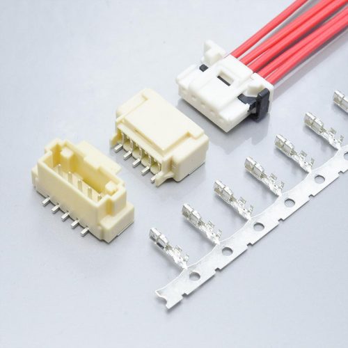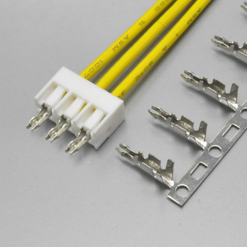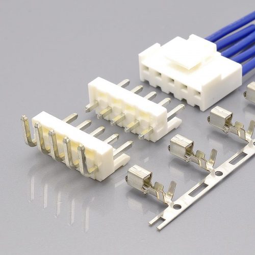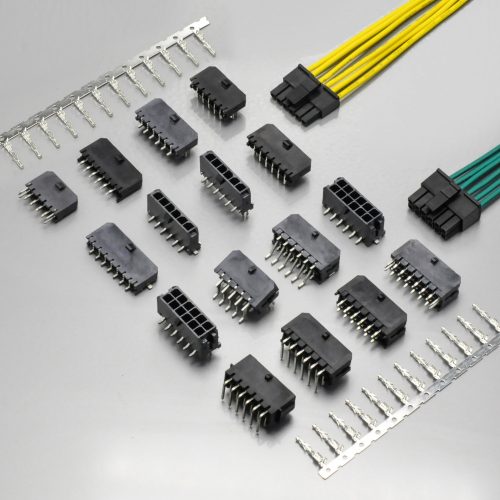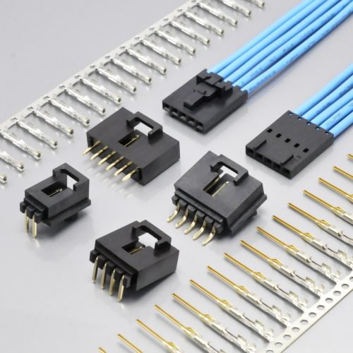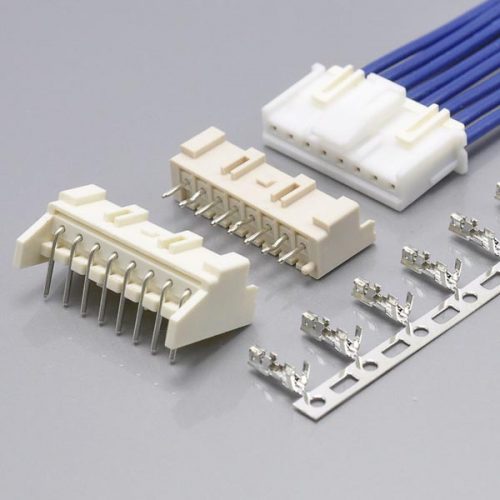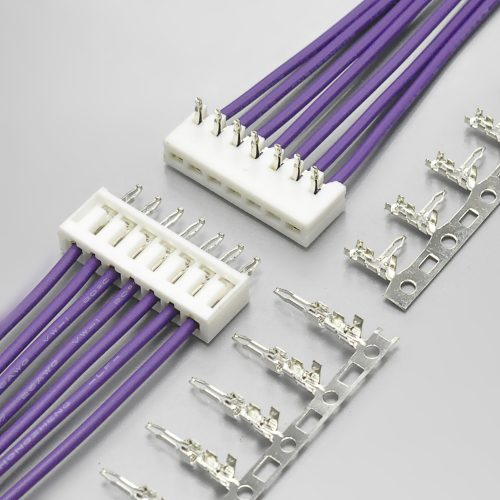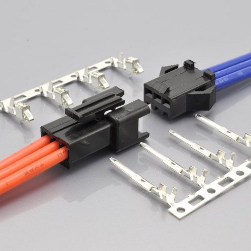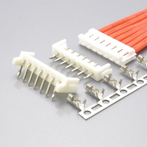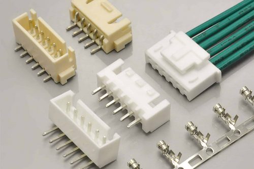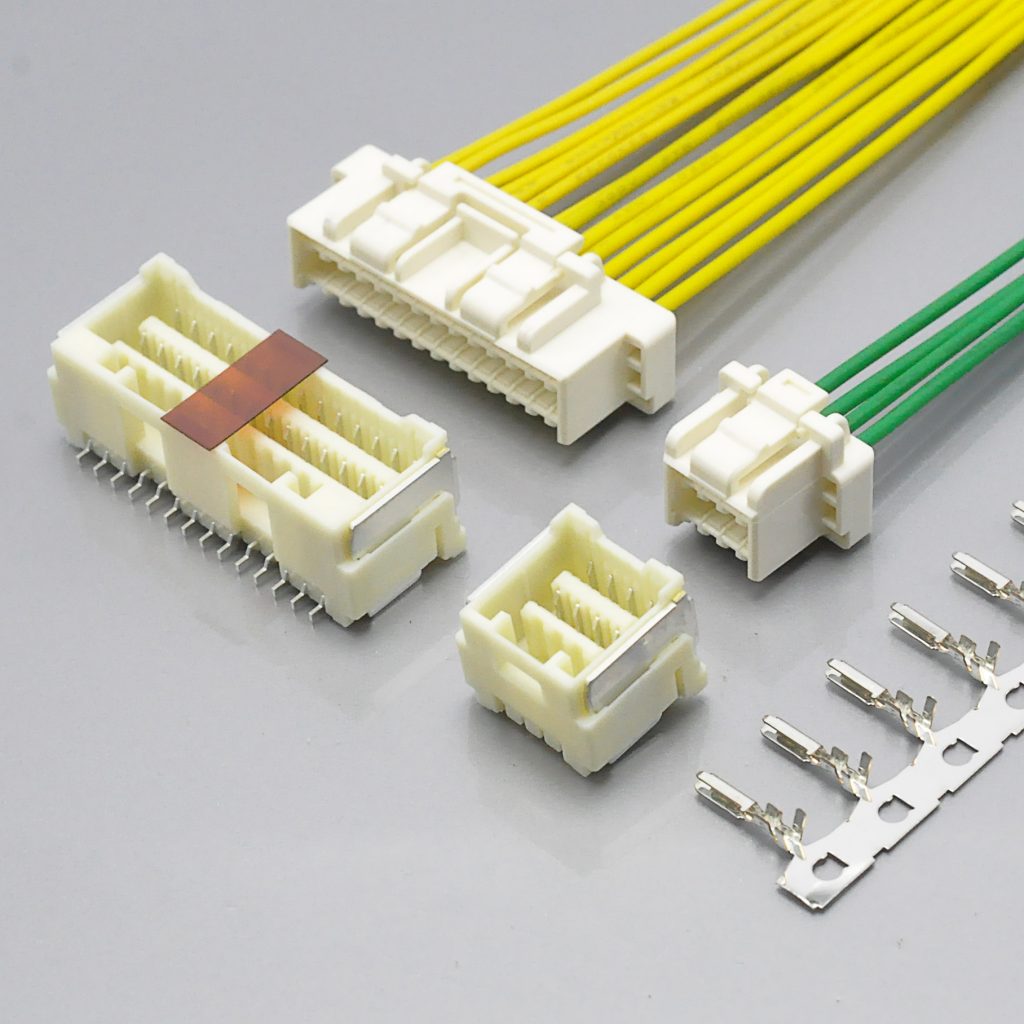
Quick answer: Molex CLIK-Mate 1.5 is a 1.50mm pitch wire-to-board system with an inner positive lock, a tuning-fork terminal, and SMT wafer options, in both single-row and dual-row versions. The current rating is not one number. Molex’s own reference guide quotes 3.0A, but attaches two conditions in the same footnote — “when using minimum circuit size and maximum wire gauge” — and adds that the figure “is for reference only”. The formal product specification for the dual-row version rates the same system at 2.0A at AWG #24, 1.5A at AWG #26, and 1.0A at AWG #28 and #30. Rated voltage is 100V AC(rms)/DC and the temperature range is −40°C to +105°C. The KONNRA KR1507 is the cross-reference equivalent, and it publishes both a single-row range (2 to 15 circuits) and a dual-row range (2×4 to 2×20).
The most useful thing you can do with this series before you specify it is decide which of those current figures applies to your design — because they differ by a factor of three, and all three of them come from the same manufacturer.
That is not a trick or a typo. It is what happens when a connector family spans two row configurations, four wire gauges and an eight-to-thirty-four-circuit range, and when the headline figure in a sales reference guide is quoted at a test condition that almost no real design actually uses. This guide works through the conditions, separates what Molex actually publishes from what circulates, and then lines up the KONNRA KR1507 against both — parameter by parameter, including the places where KONNRA’s own documents disagree with each other.
Every figure below is traceable to a source listed in the final section. Where a number is not published anywhere we could verify, we say so rather than filling the gap.
At a glance — Molex CLIK-Mate 1.5 vs the KONNRA KR1507
| Parameter | Molex CLIK-Mate 1.5 | KONNRA KR1507 single row | KONNRA KR1507 dual row |
|---|---|---|---|
| Pitch | 1.50mm | 1.50mm | 1.50mm |
| Architecture | Wire-to-board, SMT wafer | Wire-to-board, SMT wafer | Wire-to-board, SMT wafer |
| Lock type | Inner positive lock | Inner lock (“pressure internal lock”) | Inner lock (“pressure internal lock”) |
| Circuits | Single row 2–15 · Dual row 8–34 (force table) / up to 26 (reference guide) | 2–15 | 2*4–2*20 |
| Rated voltage | 100V AC(rms)/DC | 100V AC/DC | 100V AC/DC |
| Rated current | 3.0A (reference guide, qualified) · 2.0A @AWG#24 · 1.5A @#26 · 1.0A @#28/#30 (dual-row PS) | 3A (AWG #24) | 2A (24AWG) in the specification · 1.5A in the drawing |
| Temperature range | −40°C to +105°C | −40°C to +105°C | −40°C to +105°C |
| Durability | 30 cycles (tin plated) | 30 cycles | 30 cycles |
| Contact resistance | 20mΩ max | 20mΩ max (PS + drawing); page says 30mΩ | 20mΩ max |
| Insulation resistance | 500MΩ min | 500MΩ min | 500MΩ min (PS); drawing says 100MΩ |
| Dielectric strength | 500V AC(rms) / 1 min | 500V AC / 1 min | 500V AC / 1 min |
| Temperature rise | 30°C max | 30°C max | 30°C max |
| Terminal insertion force | 9.8N (1.0kgf) max | 1.0kgf (9.8N) max | 1.0kgf (9.8N) max |
| Terminal retention | 9.8N (1.0kgf) min | 1.0kgf (9.8N) min | 1.0kgf (9.8N) min |
| Header pin retention | 2.94N (0.3kgf) min | 0.3kgf (2.94N) min | 0.3kgf (2.94N) min |
| Lock strength | 29.4N (3.0kgf) min | 3.0kgf (29.4N) min | 3.0kgf (29.4N) min |
| Applicable wire | AWG #24–28 (502579) · AWG #26–30 (503429) | AWG #24–28 | AWG #24–28 |
| Insulation O.D. | φ0.78–1.28mm (502579) · φ0.7–1.02mm (503429) | 0.78–1.28mm | 0.78–1.28mm |
| Housing material | see sales drawing | PBT, UL94 V-0 | PBT, UL94 V-0 |
| Wafer material | see sales drawing | PA9T UL94 V-0 body | PA9T UL94 V-0 body |
| Plating | Tin (tin-plating variant) | Tin over nickel | Tin over nickel |
| UL file | E29179 | not stated | not stated |
| Mating durability under load | not intended (Molex usage note) | not stated | not stated |
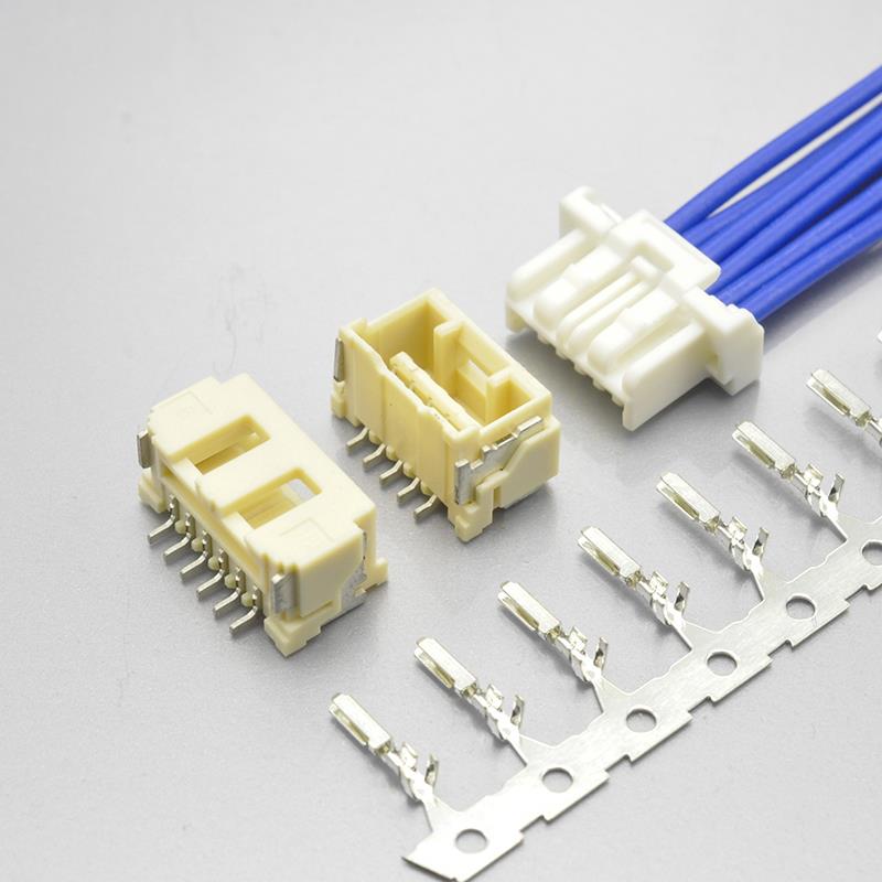
KR1507 single row — CLIK-Mate 1.5 equivalent
Four rows in that table are the ones that cause real design problems, and three of them are about current. Read the next section before you write a current figure into a specification.
The 3A figure, and the two conditions attached to it
Start with what Molex actually publishes, because the headline number comes with fine print that is easy to drop.
Molex’s Core Signal Connectors reference guide lists CLIK-Mate 1.5 with Current (max.) 3.0A and Voltage (max.) 100V, at a wire range of AWG 24–28 (502579) or 26–30 (503429), circuit sizes 2–15 single row. The footnote attached to that column reads:
“When using minimum circuit size and maximum wire gauge. Current (max.) is for reference only.”
Read those two conditions separately, because they do different things.
“Minimum circuit size” points at the derating behaviour. Current-carrying capacity in a multi-position connector falls as more positions are loaded, because the heat from adjacent contacts has nowhere to go. Molex’s dual-row product specification quantifies exactly that, and the numbers are worth printing in full:
| Wire | 8 circuits | 16 circuits | 26 circuits | 34 circuits |
|---|---|---|---|---|
| AWG #24 | 2.5A | 2.0A | 2.0A | 2.0A |
| AWG #26 | 2.0A | 1.5A | 1.5A | 1.5A |
| AWG #28 | 2.0A | 1.5A | 1.0A | 1.0A |
| AWG #30 | 1.5A | 1.0A | 1.0A | 1.0A |
The same table carries five conditions that matter as much as the numbers:
- The values are “for reference only.”
- The derating is “based on not exceeding 30 °C Temperature Rise.”
- Temperature rise is “measured in barrel area of crimp terminal” — not at the housing, not at the contact interface.
- “PCB trace design can greatly affect temperature rise results.”
- “Data is for all circuits powered.”
So the 3.0A headline describes the best case in that table — an 8-circuit connector at AWG #24, where the derating table tops out at 2.5A, and where the rated-current table in the same document says 2.0A. It is a fair figure for a small circuit count at the largest wire, and it is not a figure you can carry to a 26-position connector without checking.
“Maximum wire gauge” is the second condition, and on this series it also determines which terminal you can use. Molex publishes two terminals for the 1.5mm single row:
| Terminal | Wire range | Insulation O.D. |
|---|---|---|
5025790*00 |
AWG #24–28 | φ0.78–1.28mm |
5034290000 |
AWG #26–30 | φ0.7–1.02mm |
The 3.0A headline requires the large wire — which means it requires the 502579 terminal. Choose the 503429 terminal so you can use AWG #30 and the applicable ceiling drops to 1.0A at 16 or more circuits.
What Molex’s formal specification says, at each gauge
The dual-row product specification (series 503149, revision B) states the rated current as a short table rather than one figure:
| Wire size | Rated current (max.) |
|---|---|
| AWG #24 | 2.0A |
| AWG #26 | 1.5A |
| AWG #28 | 1.0A |
| AWG #30 | 1.0A |
That is the number to design against if you are designing against the specification rather than the reference guide: 2.0A at AWG #24, falling to 1.0A by AWG #28.
And now the KONNRA side
The KONNRA KR1507 publishes three values across four documents, and they map onto the three Molex figures almost exactly:
| KONNRA document | Published current | Which Molex figure this is |
|---|---|---|
| Single-row product specification PS-KR1507-01 §4.0 | 3A (24AWG) | Molex reference guide headline (3.0A) |
| Single-row engineering drawing | 3A (AWG #24) | same |
| Dual-row product specification PS-KR1507-02 §4.0 | 2A (24AWG) | Molex dual-row specification, AWG #24 (2.0A) |
| Dual-row engineering drawing | 1.5A | Molex dual-row specification, AWG #26 (1.5A) |
| Single-row product page (spec table) | 3A, no qualifier | Molex headline, both conditions dropped |
| Dual-row product page (spec table) | 1.5A, no qualifier | Molex AWG #26 figure, gauge dropped |
Two things are worth drawing out of that table, and neither is a criticism of KONNRA specifically.
Every KONNRA figure traces back to a real Molex figure at a real gauge. The single row quotes Molex’s headline. The dual row quotes Molex’s AWG #26 value on the drawing and Molex’s AWG #24 value in the specification. Nothing has been invented.
But the web pages drop the gauge. A page reading “Current: 3A” versus “Current: 1.5A” tells you nothing about which wire you must use to get there, and on this series that is the whole question — AWG #24 and AWG #30 are five current steps apart across the derating table at 16 circuits or more. If you are specifying from a web page, get the wire gauge confirmed before you commit the number to a drawing.
And the dual row contradicts itself. PS-KR1507-02 §4.0 says 2A (24AWG); the dual-row engineering drawing says 1.5A. Those are not the same figure, and on this series the gap between them is exactly the gap between AWG #24 and AWG #26. Both are defensible ratings; only one of them can be the one your drawing calls out. That is a question to put to the supplier in writing, and it is one of the checks in the final checklist.
The practical rule. Unless you have your own temperature-rise data on your own board, design to the lower of (the figure for your wire gauge, the figure for your circuit count) — and if you are replacing a CLIK-Mate part, design to the lower of the two suppliers’ figures. On this series that means AWG #24 at a small circuit count gives you 2.0–2.5A, and a 26-position connector at AWG #28 gives you 1.0A. Neither of those is 3A.
Single row and dual row: what actually differs
The CLIK-Mate 1.5 family covers two row configurations, and the difference is larger than the obvious one of position count. It changes which housing you order, which wafer you order, how many locks the connector has, and how much insertion force you are asking an operator to apply.
The part numbering, side by side
KONNRA’s two product specifications use a clean, parallel numbering scheme:
| Single row (PS-KR1507-01) | Dual row (PS-KR1507-02) | |
|---|---|---|
| Housing | H150701**2401A |
H150702**2401A |
| Terminal | T15070PT0101A |
T15070PT0101A |
| Wafer, 90° (SMT right angle) | C1507RS1**11M0101PA |
C1507RS2**11M0101RA |
| Wafer, 180° (SMT straight) | C1507VS1**11M0101RA |
C1507VS2**11M0101RA |
| Circuits | 2P to 15P | 2*4 to 2*20 |
Read the wafer numbers carefully, because the row configuration is encoded in a single character. The digit 1 after RS or VS means single row; the digit 2 means dual row. Everything else in the part number is common. That is convenient for a bill of materials and dangerous for a manual data entry — C1507RS1... and C1507RS2... differ by one digit and by a completely different housing.
Note also that the wafers carry a suffix that distinguishes them: the single-row right-angle wafer is C1507RS1**11M0101P**A (P) while the single-row straight wafer is C1507VS1**11M0101R**A (R). Confirm the suffix against the drawing rather than assuming.
The same terminal serves both variants
This is the single most useful fact about ordering this series: undefined is the terminal for both the single-row and the dual-row KR1507. Both product specifications list the identical terminal part number.
The consequences are practical:
- One terminal part number to stock, one crimp setup, one set of applicator settings, whether you build single-row or dual-row harnesses.
- The crimp specification is shared — the same crimp heights, widths and pull-strength requirements apply to both.
- A change to the terminal affects both variants, which is worth knowing when you qualify a second source or approve a material change.
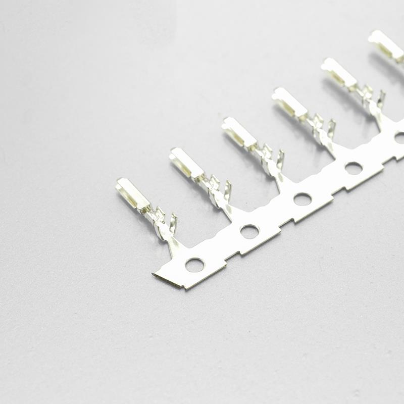
KR1507 terminal — shared by the single-row and dual-row variants
The wire range stops at AWG #28 — and that is a real cross-reference limit
Here is where the KR1507’s coverage is narrower than the Molex system it cross-references, and it is easy to miss because it hides in a four-character range.
Both KONNRA specifications, and both engineering drawings, state the applicable wire as:
AWG 24# ~ 28#, Insulation O.D. 0.78 to 1.28mm
Molex’s system reaches further in both directions of gauge, because it offers two terminals:
| Molex | KONNRA KR1507 | |
|---|---|---|
| Large-wire terminal | 5025790*00 — AWG #24–28, φ0.78–1.28mm |
T15070PT0101A — AWG #24–28, 0.78–1.28mm |
| Small-wire terminal | 5034290000 — AWG #26–30, φ0.70–1.02mm |
no equivalent published |
So:
- AWG #30 is not supported by the KR1507. Molex reaches it with the
5034290000terminal; KONNRA publishes no KR1507 terminal for it. - Insulation below 0.78mm is not supported either. Molex’s small-wire terminal accepts an insulation O.D. down to 0.70mm. The KR1507’s published window starts at 0.78mm. A wire with 0.75mm insulation is inside the Molex window and outside KONNRA’s.
- The crimp specifications published by KONNRA are for 24, 26 and 28 AWG only. There is a 30 AWG column in neither.
If your design uses AWG #30, or a thin-wall insulation below 0.78mm, this cross-reference does not cover it as published — that is a question for the supplier, not an assumption to make. If your design uses AWG #24–28 with standard insulation, the wire side of the cross-reference is a like-for-like match, and the insulation window is identical to Molex’s large-wire terminal down to two decimal places.
How many locks, and why it changes with position count
One detail in KONNRA’s single-row drawing is worth pulling out, because it is the kind of thing that only shows up when you compare a 3-position connector against a 15-position one.
The drawing annotates the housing with three circuit groups:
| Circuit range | Lock count |
|---|---|
| 2P–3P | 1 lock |
| 4P–5P | 1 lock |
| 6P–15P | 2 locks |
So a 2-position housing is held by a single lock, and a 15-position housing by two. That matters for two reasons. First, retention scales with position count — a long housing with one lock would be a lever waiting to be pried open. Second, your insertion and withdrawal forces scale with position count as well, which is exactly what the force table later in this guide shows: from 0.66 kgf insertion at 2 positions to 4.95 kgf at 15.
The dual-row drawing groups its mated-connector views differently — 2x4~2x5, 2x6~2x9, and 2x10~2x20 — which reflects the same idea over a larger connector body.
The locking system: this is the feature the series is named for
“CLIK-Mate” is named for the audible confirmation of mating, and the lock is the part of this connector that most distinguishes it from a friction-lock alternative.
Molex describes the mechanism as an inner positive lock and specifies its strength directly in the dual-row product specification:
6.2.6 Housing Lock Strength (Positive Lock) — Mate connectors and apply axial pull out force at the speed rate of 25±3 mm/minute. — 29.4N {3.0kgf} MIN
KONNRA specifies the same test and the same figure, worded almost identically:
6.5 自锁装置强度 Lock Retention Force — Mate connectors and apply pull-out force at the speed rate of 25±3mm/minute. — 3.0 kgf (29.4 N) min.
29.4 newtons is the force required to pull a correctly mated pair apart without releasing the lock. Put it next to the other retention figures in the same document set and the design intent becomes clear:
| Retention figure | Molex | KONNRA | What it holds |
|---|---|---|---|
| Crimp terminal retention force | 9.8N (1.0kgf) min | 1.0kgf (9.8N) min | Terminal in the housing |
| Header terminal retention force | 2.94N (0.3kgf) min | 0.3kgf (2.94N) min | Pin in the wafer |
| Housing lock strength | 29.4N (3.0kgf) min | 3.0kgf (29.4N) min | Mated pair |
The mated-pair lock is three times stronger than the retention of a single crimped terminal in its housing, and ten times stronger than a pin’s retention in the wafer. That is the correct ordering: the lock is the strong element, so that when something gives under an unexpected load at a connector this size, it gives at a serviceable interface rather than by pulling a terminal out of a housing.
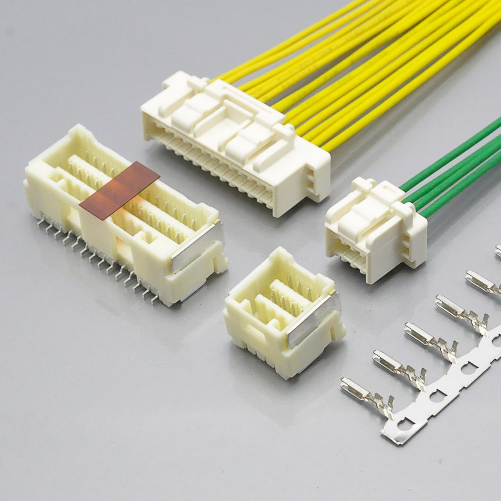
KR1507 dual row — inner lock with audible mating confirmation
Unmating is a two-handed operation, by design
Molex’s usage instructions are explicit about how to release it, and they describe a deliberate action rather than a pull:
“When unmated connectors, positive locks shall be released. Please grip all the wire together, push “lock release bar” with “lock protection wall” to release the lock, then pull out slowly.”
Two details in that sentence are design features rather than instructions. “Grip all the wire together” spreads the load across the whole housing instead of concentrating it on the wire nearest your hand — which is exactly how you avoid peeling one terminal out of a multi-position connector. “Push the lock release bar with the lock protection wall” means the release feature is guarded, so the lock cannot be opened by a wire brushing past it.
And there is a firm rule about when you may not do it at all. Molex’s note 27 in the same document reads:
“This product is not designed for the mating and unmating of the connectors to be performed under the condition of an active electrical circuit. It may cause a spark and product defect if the connectors are mated and unmated in this way.”
So: not a hot-plug connector. If your application requires disconnection under load, this family is the wrong choice regardless of which supplier you buy it from — and that is true of the KONNRA equivalent too, since it is the same contact geometry and the same lock.
Durability, and what it is rated for
Both suppliers rate the series at 30 mating cycles:
- Molex: “Durability — Plating Type: Tin Plated — Number of Cycles: 30 cycles”
- KONNRA: “耐久性 Durability — When mated up to 30 cycles repeatedly by the rate of 10 cycles per minute. (Based upon EIA-364-09C)”
KONNRA adds the test detail and the acceptance criterion, which Molex states separately in its repeated-insertion test: after 30 cycles, contact resistance must remain at or below 40mΩ — double the 20mΩ initial limit.
30 cycles is a modest number, and it is a deliberate one. This is a connector meant to be mated at assembly and left alone. If your application involves periodic field service where a technician unplugs and replugs the harness, count those events against 30 — and note that the force table publishes both initial and 30th-cycle withdrawal forces, both of which are identical, so at least the retention does not degrade over the rated life.
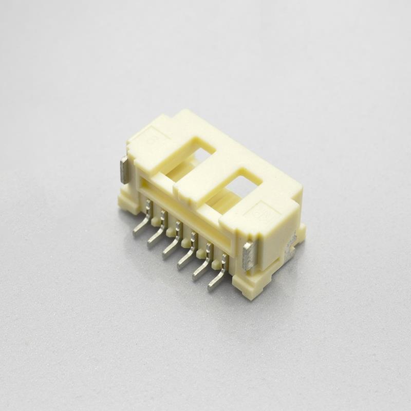
KR1507 single row right-angle wafer
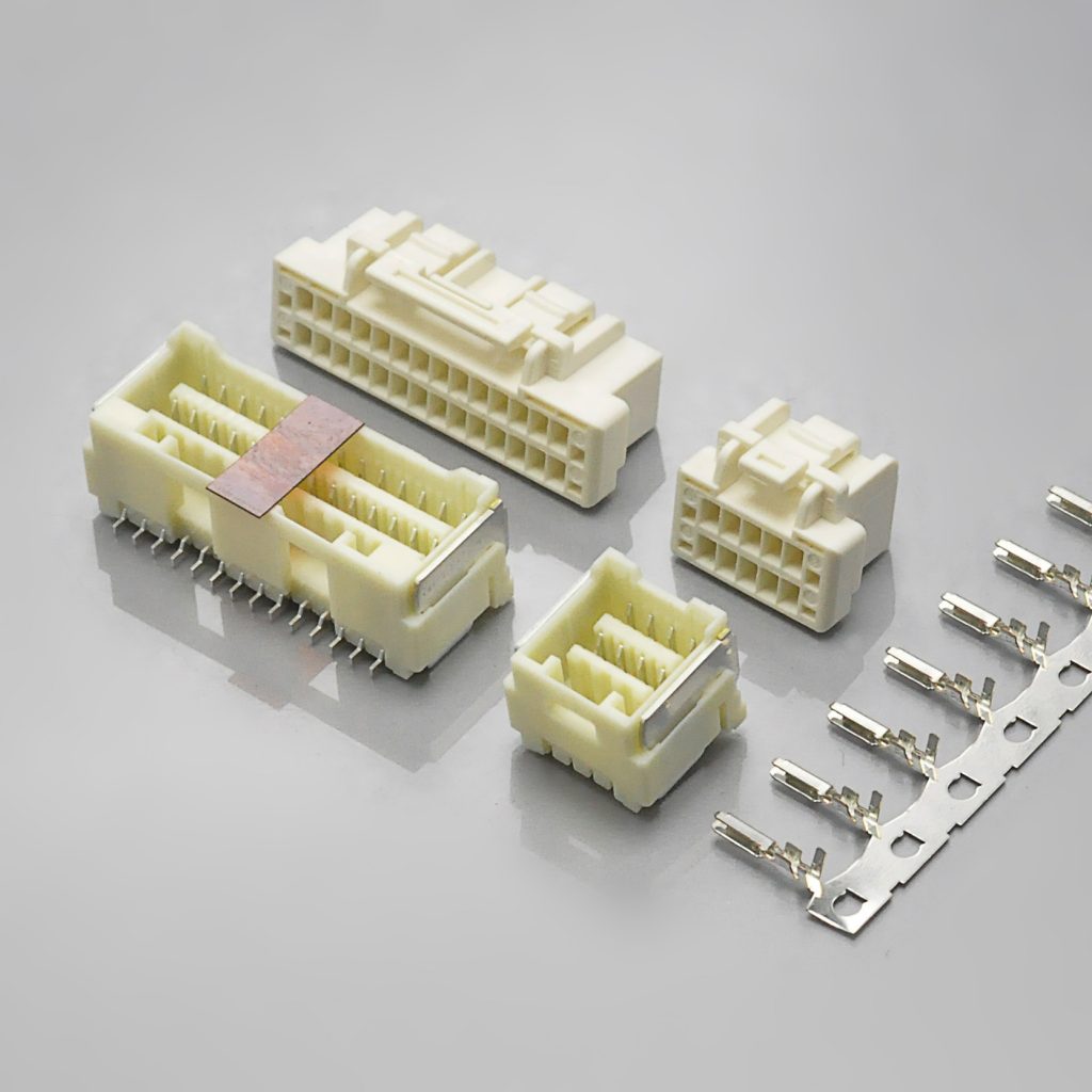
KR1507 dual row wafer and terminal
How to identify whether your connector is a CLIK-Mate 1.5
The 1.50mm pitch class contains at least six distinct families from two manufacturers, and several of them look alike from above. Work through these questions in order — question 2 is the decisive one on this class.
1. Measure the pitch across several positions. 1.50mm on centres. That eliminates the 1.25mm and 1.20mm families (PicoBlade, Pico-EZmate, DF13, DF14, ACH, Micro-Lock Plus 1.25) and the 2.00mm and 2.50mm families (Micro-Latch, Milli-Grid, PH, XH). Measure across at least four pitches and divide — a 1.5mm connector that has been mis-measured as 1.25mm is one of the most common identification errors on a populated board.
2. Where is the lock, and is there one? This is the question that separates the 1.50mm families from each other, because in this pitch class the lock position is the defining architectural difference:
- Lock inside the mating cavity, with a click you can hear and feel → an inner positive lock. On this class that points to CLIK-Mate 1.5 or Molex Spot-On 1.5, both of which Molex documents as “Inner Positive”.
- Lock on the side of the housing, engaged by a visible finger or barb → a side positive lock, which on this class means Pico-Lock 1.5.
- No lock at all — retention by friction between the terminal and the wafer → Pico-SPOX 1.5, documented by Molex as “Friction”.
- No wafer at all, and the housing is soldered straight to the board → a board-in connector, which in this pitch class is the JST SZN / KR1502.
If you can hear a distinct click at the end of insertion and the housing will not release without a deliberate unlatching action, you are looking at the inner-positive-lock group, and CLIK-Mate is the enhanced-tier member of it.
3. Count positions and rows. CLIK-Mate 1.5 covers single row 2–15 and dual row. Molex’s dual-row product specification publishes an insertion/withdrawal table running from 8 to 34 circuits; the reference guide lists dual-row circuit sizes from 8 up to 26. KONNRA’s dual-row range runs 2×4 to 2×20, which is 8 to 40 circuits.
If you count more than 15 positions in a single row, or an odd dual-row count, this is not CLIK-Mate.
4. Look for the tuning-fork contact. The series uses what Molex describes as a tuning-fork terminal and KONNRA describes as a “unique tuning-fork terminal concept”, providing low insertion force and a firm mating contact. If the wafer’s contact is a single flat blade rather than a forked pair, you are looking at a different family.
5. Read any markings, then convert them. Molex’s part numbers for this family are grouped by function — single row uses the 502578 / 502579 / 502584 / 502585 block, dual row the 503149 / 503148 / 503154 block, with through-hole and bottom-entry options in 503159 / 503175 / 503395 and gold-plated variants in the 2130xx / 2132xx range. KONNRA’s equivalents carry a C1507 wafer prefix, an H1507 housing prefix and T15070 for the terminal.
6. Check the wire you would need. The KR1507 takes AWG #24–28 with insulation 0.78–1.28mm. If the harness in your hand is AWG #30, the KR1507 as published does not cover it — see the wire-range section above.
Where CLIK-Mate 1.5 sits in the 1.50mm class
The 1.50mm pitch is unusually crowded, and the families differ in ways that matter more than their current ratings. The table below is built from Molex’s own Core Signal Connectors reference guide, so the lock types and ratings are the manufacturer’s own published positioning:
| Pitch | Family | Lock type | Circuits | Wire range | Current (max.) | Voltage (max.) | Molex tier |
|---|---|---|---|---|---|---|---|
| 1.50mm | CLIK-Mate 1.5 | Inner positive | 2–15 single · 8–26 dual | AWG 24–28 / 26–30 | 3.0A | 100V | Enhanced |
| 1.50mm | Pico-Lock 1.5 | Side positive | 2–12 | AWG 24–32 | 3.5A | 150V | Pro |
| 1.50mm | Pico-SPOX 1.5 | Friction | 2–15 | AWG 24–26 / 24–30 | 3.5A | 250V | Basic |
| 1.50mm | Spot-On 1.5 | Inner positive | 2–16 single · 10–40 dual | AWG 24–28 | 4.0A single / 2.5A dual | 100V | Unique |
| 1.80mm | Pico-EZmate HC | Friction | 2–5 | AWG 22–24 | 5.0A | 250V | Pro |
Three observations fall straight out of that table, and all three are useful when someone asks you why you did not simply pick the highest current rating in the pitch class.
The highest current ratings in the class do not come with a positive lock. Pico-SPOX 1.5 quotes 3.5A and 250V, and Pico-Lock 1.5 quotes 3.5A and 150V — both above CLIK-Mate’s 3.0A headline. But Pico-SPOX is a friction-lock connector, and Pico-Lock’s lock is on the side. That is the trade: the higher-current 1.5mm options give up either the lock or its position.
Only two families in the class have an inner positive lock, and CLIK-Mate is the cheaper of them. Spot-On 1.5 also uses an inner positive lock and also quotes 100V, and it reaches 4.0A in single row — but only 2.5A in dual row, and Molex files it under a different tier. If your requirement is specifically “inner positive lock at 1.50mm”, the choice is between these two, and the deciding factor will usually be circuit count and availability rather than current.
Circuit count is often the real filter. CLIK-Mate’s single row reaches 15 positions. Pico-Lock reaches 12, Pico-EZmate HC only 5, JST GH 6 (via the KONNRA KR1506 equivalent). If you need 14 positions in a 1.50mm single row with a lock, much of that table is already eliminated before you compare a single electrical parameter.
For reference, the KONNRA cross-reference entries in this pitch class position as follows — figures as published on KONNRA’s own 1.5mm pitch index:
| KONNRA series | Cross-references to | Architecture | Current | Voltage | Circuits |
|---|---|---|---|---|---|
| KR1507 (dual row) | Molex CLIK-Mate 1.5 | Wire-to-board | 1.5A | 100V | 2*4–2*20 |
| KR1507 (single row) | Molex CLIK-Mate 1.5 | Wire-to-board | 3A | 100V | 2–15 |
| KR1500 | Molex Pico SPOX 1.5 | Wire-to-board | 2.5A | 250V | 2–15 |
| KR1511 | 1.50mm single row W2B | Wire-to-board | 3A | 100V | 2–15 |
| KR1501 | JST ZH 1.5 | Wire-to-board | 1A | 100V | 2–16 |
| KR1502 | JST SZN 1.5 | Board-in | 1A | 200V page / 50V spec | 2–16 |
| KR1506 | JST GH 1.5 | Wire-to-board | 1A | 50V | 2–6 |
Note how the two KR1507 rows carry different current figures for the same series — 3A for single row and 1.5A for dual row — which is the same single-row-versus-dual-row distinction that Molex makes in its own tables, restated at the index level. And note that the KR1504 entry, which cross-references JST’s 1.5mm board-in family, is a different architecture entirely.
Where KONNRA’s own documents disagree
We compared the KR1507’s published web pages against its controlled specification documents, and the specification documents against each other. Six discrepancies came out, and they are worth listing precisely — not because they are unusual for a cross-reference supplier, but because each one is a number you might otherwise copy into a drawing.
1. The single-row page’s contact resistance does not match its own specification
| Source | Contact resistance |
|---|---|
| Single-row specification PS-KR1507-01 §5.1 | 20 milliohms Max |
| Single-row engineering drawing, item 6 | 20mΩ Max |
| Single-row product page | 30mΩ max |
Two controlled documents say 20mΩ; the web page says 30mΩ. The controlled figure is 20mΩ, and it matches Molex’s own dual-row specification (“Contact Resistance … 20 milliohms MAX”), so 20mΩ is also the figure that makes the cross-reference hold.
2. The dual-row page’s insulation resistance does not match its own specification either
| Source | Insulation resistance |
|---|---|
| Dual-row specification PS-KR1507-02 §5.2 | 500 Megohms Min |
| Dual-row engineering drawing, item 4 | 100MΩ / min |
| Dual-row product page | 100MΩ/ min |
| Molex dual-row product specification | 500 Megohms MIN |
Here the web page and the engineering drawing agree with each other at 100MΩ, while the specification and Molex both say 500MΩ. There is a plausible reason this happened, and it is the same one we found on another series: the single-row specification’s humidity test relaxes the insulation resistance to 100MΩ minimum after 96 hours at 90–95% RH. If a 100MΩ figure was copied out of a post-humidity line into a general specification, it would land exactly here.
Either way, the figure to design against is 500MΩ — that is the initial requirement in the specification, and it is what Molex publishes.
3. The dual-row current rating differs between KONNRA’s own specification and drawing
PS-KR1507-02 §4.0 says 2A (24AWG). The dual-row engineering drawing says 1.5A. Both are legitimate Molex figures for this system — 2.0A at AWG #24 and 1.5A at AWG #26 — but they are not the same rating, and only one can be the controlled value.
This is the discrepancy in the list that most needs a written answer, because it is the parameter a customer is most likely to design to.
4. The dual-row terminal material is described differently in three places
| Source | Terminal material |
|---|---|
| Dual-row specification PS-KR1507-02 §3.0 | Phosphor bronze |
| Dual-row engineering drawing | Phosphor Bronze |
| Dual-row product page | Copper Alloy |
Phosphor bronze is a copper alloy, so the page is not wrong in substance — it is simply less specific. Note that the dual-row drawing describes the wafer contact and the solder nail both as “Copper alloy”, while the specification gives the wafer contact as phosphor bronze and the solder tab as brass. If your qualification document needs the base metal, take it from the specification.
5. Unit symbols are rendered as “Q” on the product pages
Both product pages display resistance values with the ohm symbol replaced: “Contact Resistance: 20m Q/max”, “30m Q/max”, “Insulation Resistance: 100MQ/ min”. The intended values are mΩ and MΩ. It is a rendering artefact rather than a data error, but if you are copying a specification from a web page, confirm the units against the PDF.
6. The dual-row product page exists twice
KONNRA publishes the KR1507 dual row at two URLs with identical content:
/product/kr1507-equivalent-to-molex-mx1-5-alternatives-connector//product/kr1507-series-clik-mate-dual-row-wire-to-board-connector/
Both carry the same title pattern, the same specification table, the same component links and the same document downloads. For a buyer this is a real risk: two pages can be indexed, quoted and linked separately while carrying the same manufacturer part numbers, which makes it harder to be sure you are looking at the current page. It also splits any inbound search authority between two URLs instead of concentrating it on one. Nothing about the product changes — but if you are building a reference document, cite the specification PDF rather than either page.
The force specification is one rule, and both suppliers publish the same one
Insertion and withdrawal force is where a cross-reference claim is easiest to check and hardest to fake, because a force table is 20-odd numbers that either line up or do not.
Molex publishes a force table for the dual row running from 8 to 34 circuits, at the 1st, 6th and 30th insertion. KONNRA publishes two tables — one for the single row from 2P to 15P and one for the dual row from 2*4 to 2*20. Compared directly:
| Circuits | Molex insertion (max), 1st | KONNRA insertion (max), initial | Molex withdrawal (min) | KONNRA withdrawal (min) |
|---|---|---|---|---|
| 8 | 25.9N {2.64kgf} | 2.64 | 1.6N {0.16kgf} | 0.16 |
| 10 | 32.3N {3.30kgf} | 3.30 | 2.0N {0.20kgf} | 0.20 |
| 12 | 38.8N {3.96kgf} | 3.96 | 2.4N {0.24kgf} | 0.24 |
| 14 | 45.25N {4.62kgf} | 4.62 | 2.8N {0.28kgf} | 0.28 |
| 16 | 51.7N {5.28kgf} | 5.28 | 3.2N {0.32kgf} | 0.32 |
| 18 | 58.15N {5.93kgf} | 5.93 | 3.6N {0.36kgf} | 0.36 |
| 20 | 64.6N {6.59kgf} | 6.59 | 4.0N {0.40kgf} | 0.40 |
| 22 | 71.2N {7.26kgf} | 7.26 | 4.4N {0.44kgf} | 0.44 |
| 24 | 77.6N {7.92kgf} | 7.92 | 4.8N {0.48kgf} | 0.48 |
| 26 | 84.1N {8.58kgf} | 8.58 | 5.2N {0.52kgf} | 0.52 |
| 28 | 90.6N {9.24kgf} | 9.24 | 5.6N {0.57kgf} | 0.56 |
| 30 | 97.1N {9.90kgf} | 9.90 | 6.0N {0.61kgf} | 0.60 |
| 32 | 103.5N {10.56kgf} | 10.56 | 6.4N {0.65kgf} | 0.64 |
| 34 | 106.7N {10.88kgf} | 11.22 | 6.6N {0.67kgf} | 0.68 |
Thirteen of the fourteen rows match exactly. That is a stronger statement about a cross-reference than any single rating, because a force table cannot be matched by coincidence — you either build the contact to the same geometry or the numbers diverge.
The single rule behind every number in that table
Look at the progression rather than the individual values. In KONNRA’s tables, every circuit added is worth 0.33 kgf of insertion force and 0.02 kgf of withdrawal force — and the same law holds in Molex’s table:
- KONNRA single row, 2 positions: 2 × 0.33 = 0.66 kgf insertion, 2 × 0.02 = 0.04 kgf withdrawal ✓
- KONNRA single row, 15 positions: 15 × 0.33 = 4.95 kgf, 15 × 0.02 = 0.30 kgf ✓
- KONNRA dual row, 8 circuits: 8 × 0.33 = 2.64 kgf, 8 × 0.02 = 0.16 kgf ✓
- KONNRA dual row, 40 circuits: 40 × 0.33 = 13.20 kgf, 40 × 0.02 = 0.80 kgf ✓
- Molex dual row, 8 circuits: 2.64 kgf / 0.16 kgf — the same law ✓
- Molex dual row, 32 circuits: 10.56 kgf / 0.64 kgf — still the same law ✓
So the specification is not 34 separate measurements. It is one linear rule, applied across both row configurations and both suppliers, and the tables are that rule evaluated at each position count. That is a genuinely useful thing to know: it means you can sanity-check any claimed force figure by multiplying the position count by 0.33, and it means a quoted force that does not fit the rule is worth questioning.
The one row that does not match, and which document is the odd one out
At 34 circuits, KONNRA publishes 11.22 kgf / 0.68 kgf and Molex publishes 106.7N {10.88 kgf} / 6.6N {0.67 kgf}.
KONNRA’s figure is the one that follows the rule: 34 × 0.33 = 11.22 and 34 × 0.02 = 0.68. Molex’s 34-circuit row is the only row in its own table that breaks its own increment — every other step in that document adds 0.33 kgf of insertion force, and its 24th-to-34th progression is short by 0.34 kgf. Its withdrawal figure at that row is similarly short by 0.01 kgf.
We are not going to assert that this is a typographical error in Molex’s document; that is for Molex to say. What can be stated is the observation: at every circuit count from 8 to 32 the two suppliers agree exactly, and at 34 circuits KONNRA’s values continue the linear progression that Molex’s own table establishes everywhere else. If your design uses a 34-circuit (2×17) dual-row connector and the insertion force matters, that is a row worth confirming with both suppliers rather than picking a number.
What this means in the hand
Insertion force is an operator-experience number as much as an engineering one, and this series is specified for hand mating — Molex’s own test condition for 6.2.1 reads “Insert and withdraw connectors with hand.”
| Connector | Insertion force (max) | Feel |
|---|---|---|
| Dual row, 8 circuits (2×4) | 2.64 kgf | light |
| Single row, 15 positions | 4.95 kgf | firm |
| Dual row, 20 circuits (2×10) | 6.59 kgf | heavy |
| Dual row, 40 circuits (2×20) | 13.20 kgf | needs two hands and a method |
Thirteen kilograms of insertion force on a 34mm-wide connector is a real assembly-line consideration. It is the direct consequence of a positive lock rated at 3.0 kgf minimum combined with a contact count that scales linearly — the lock has to be strong enough to hold a large connector, and the force to close it scales with it. If your process involves a 2×20 connector, plan the mating method (fixture, guide pins, or a press) rather than assuming an operator will push it home by hand.
Note also that KONNRA’s table publishes the 30th-cycle withdrawal force as identical to the initial value at every position count — 0.16 at 8 circuits, 0.80 at 40 — so the retention does not degrade across the rated 30-cycle life. Molex’s table shows the same equality in its withdrawal columns.
Crimp and tooling
Because one terminal serves both row configurations, there is one crimp specification for the whole series — and it is the same in both KONNRA product specifications:
| Crimp parameter | 24 AWG | 26 AWG | 28 AWG |
|---|---|---|---|
| Crimp width (conductor) | 1.03 ± 0.03 | 1.03 ± 0.03 | 1.03 ± 0.03 |
| Crimp height (conductor) | 0.65 ± 0.05 | 0.60 ± 0.05 | 0.55 ± 0.05 |
| Crimp width (insulation) | 1.23 max | 1.23 max | 1.23 max |
| Crimp height (insulation) | 1.50 max | 1.40 max | 1.25 max |
| Crimp strength | 3.63 kgf min | 2.27 kgf min | 1.36 kgf min |
| Stripping length | 1.3–1.8mm | 1.3–1.8mm | 1.3–1.8mm |
KONNRA’s crimp strength requirements are stricter than Molex’s
Put the two side by side, converting Molex’s newton figures to kilograms-force:
| Wire | Molex crimp pull-out (min) | KONNRA crimp strength (min) | Ratio |
|---|---|---|---|
| AWG #24 | 29.4N {3.0kgf} | 3.63 kgf | 1.21× |
| AWG #26 | 19.6N {2.0kgf} | 2.27 kgf | 1.14× |
| AWG #28 | 9.8N {1.0kgf} | 1.36 kgf | 1.36× |
KONNRA’s minimum pull strength is higher than Molex’s at every gauge — and the margin is largest at the smallest wire, where crimp quality is hardest to control. That is a meaningful qualification point in favour of the cross-reference part, and it is worth putting in a supplier qualification file: if your incoming inspection uses Molex’s figures as the acceptance criterion, the KR1507 will pass with margin.
Molex publishes pull-out force for AWG #30 as well (4.9N {0.5kgf} min). KONNRA publishes no 30 AWG crimp column, consistent with the KR1507’s wire range stopping at AWG #28.
Tooling
Molex’s dual-row specification points to an Application Tooling Specification for the terminals and states: “ATS for terminals is not provided in this document. ATS for terminals can be available from respective terminal part number page in Molex.com.” The terminal part number — 5025790*00 or 5034290000 — is where the applicator and die information lives.
KONNRA publishes the crimp dimensions and the pull-strength requirements but no applicator part numbers, so the tooling is matched to the crimp table rather than to a named die set. Either way, the crimp height window is narrow — 0.10mm wide at every gauge — and it moves down by 0.05mm per wire step. That is why the insulation O.D. window matters as much here as it did on the current rating: a wire with oversized insulation cannot be closed to the specified conductor crimp height, and the pull strength figures become theoretical.
One detail in KONNRA’s table is easy to misread. The conductor crimp width is the same 1.03 ± 0.03mm at all three gauges, while the crimp height changes. That is normal — the width is set by the terminal’s barrel geometry while the height is set by the tool’s stroke — but it means a single width measurement cannot tell you whether you are set up for 24 AWG or for 28 AWG. Measure the height.
SMT process and board layout
This is an SMT connector on the wafer side, and the wafers carry solder nails as well as contact tails, so the process notes matter more than they would on a through-hole part.
Reflow conditions
KONNRA publishes both an SMT and a wave profile:
| SMT infrared reflow (§9.1) | Wave soldering (§9.2) | |
|---|---|---|
| Peak temperature | 255 ± 5°C, 5–10 seconds | 250°C max, 3–5 seconds |
| Time above 230°C | 20–40 seconds | 60–150 seconds above 217°C |
| Reflow zone | 90–120 seconds | 60–180 seconds |
| Pre-heat | 150–200°C | 150–180°C |
Molex specifies the reflow solder temperature as 245°C maximum, and separately notes that the upper surface of the housing tolerates up to 280°C with pre-heating, provided the parts have been left at 60°C for 24 hours or more beforehand. KONNRA’s published SMT peak is 255 ± 5°C, which sits above Molex’s 245°C headline but inside the 280°C housing-surface allowance — provided your profile is measured at the housing surface, which is where Molex’s allowance is stated. Confirm which point your profile is referenced to before comparing the two numbers, and run your own profile check on your own board rather than adopting either figure.
Both suppliers say the same thing about validating the profile yourself. Molex: “Please investigate the mounting condition (reflow soldering condition) on your own devices beforehand.” KONNRA: “please check welding conditions by your own devices beforehand. Because the condition changes by the soldering devices, P.C.boards, and so on.”
Board layout
KONNRA’s drawings state a recommended PCB layout total tolerance of ±0.05mm, and carry a general tolerance block of X.X ± 0.30 · X.XX ± 0.20 · X.XXX ± 0.10 · angle ± 2°. The housing and wafer tables advance the A dimension by exactly 1.5mm per position — the pitch — with no cumulative tolerance stated.
Molex takes a different approach and declines to treat its published pattern as a specification:
“In the case of changing our recommended board pattern size and designing, please consult in advance because it may cause a mounting issues and soldering defect and more.”
and
“In the case of changing our recommended board pattern size and designing, please consult in advance because it may cause a fatal defect.”
That is worth reading as a design instruction rather than boilerplate. The current derating table already tells you “PCB trace design can greatly affect temperature rise results” — so on this series the board pattern is not only a fit question, it is a thermal one.
Two process notes from Molex that are specific to this connector and easy to skip:
“If you leave any soldering area on this product open, there may be the possibility of a missing terminal short circuiting between pins, terminal buckling or the potential for the connector to come off of the printed circuit board. Therefore, please solder all of the terminals and fitting nails on the printed circuit board.”
Solder every tail and every nail. Partially soldering a wafer to save process time is the documented route to a shorted pin, a buckled terminal or a connector that lifts off the board.
“In the case of metal stencil of more than that solder volume used in our evaluation, please consult in advance because it may cause a flux wicking and more defect.”
Molex evaluated with a T = 0.1mm stencil at 100% aperture ratio. A thicker stencil or a higher aperture ratio puts more solder paste on the joint than the qualification was run with, and the documented failure mode is flux wicking.
And one dimensional detail worth checking on the dual row. In KONNRA’s dual-row wafer table, the B dimension runs 4.50, 6.00, 7.50 … in clean 1.5mm steps up to 2*18P at 25.50 — then 2*19P at 28.00 and 2*20P at 28.50. The 2*19P value is the only entry in the table that breaks the 1.5mm progression (25.50 → 27.00 → 28.50 would be the pattern). The housing table for the same positions steps cleanly. If you are laying out a 2×19 dual-row wafer, confirm that dimension against the current drawing rather than transcribing it.
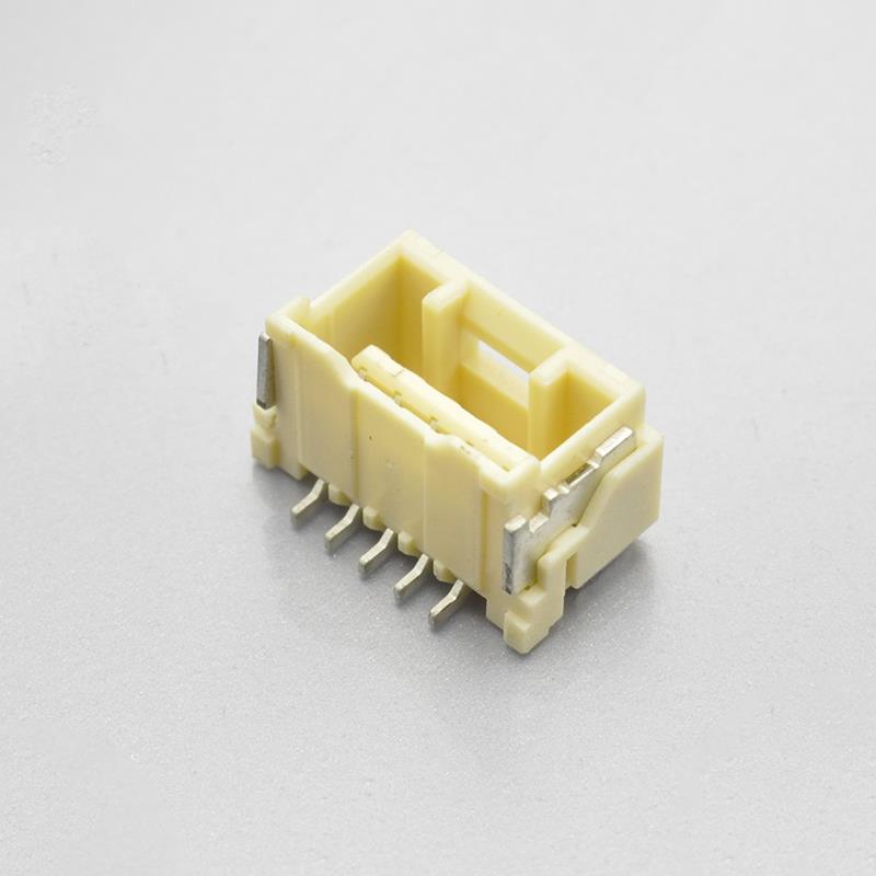
KR1507 single row SMT straight wafer
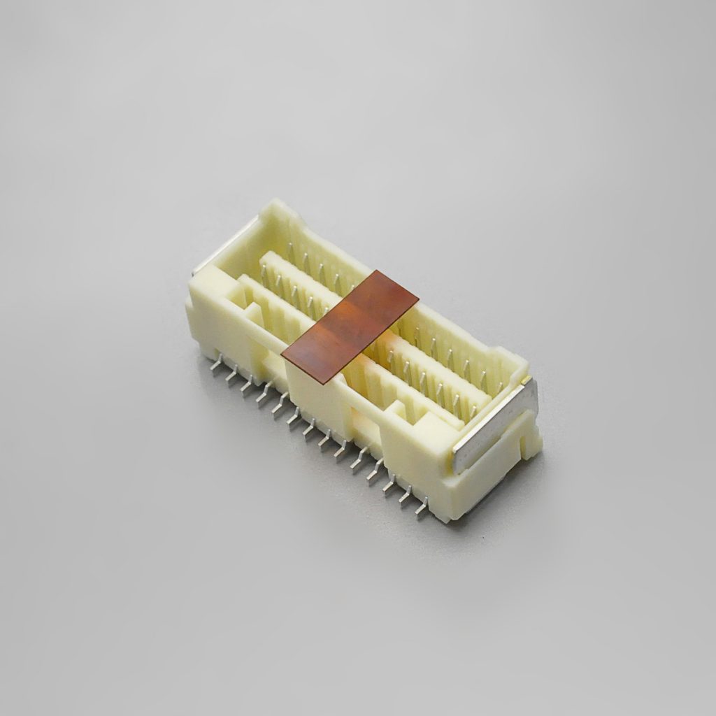
KR1507 dual row SMT straight wafer
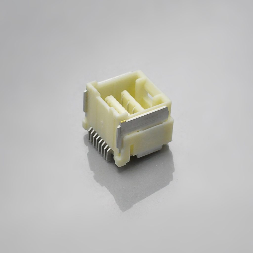
KR1507 dual row SMT right-angle wafer
Environmental qualification: the dual row mirrors Molex, the single row is a lighter subset
This is the part of the comparison that a procurement file actually needs, because on a cross-reference part the question is not only “does it fit” but “was it tested to the same programme.”
Molex publishes a full environmental section in its dual-row specification. KONNRA publishes two — one per row configuration — and they are not the same document with different position counts. Side by side:
| Test | Molex (dual-row PS) | KONNRA dual row | KONNRA single row |
|---|---|---|---|
| Durability | 30 cycles | 30 cycles | 30 cycles |
| Temperature rise | 30°C max | 30°C max | 30°C max |
| Vibration | 1.52mm P-P, 2h/axis, discontinuity ≤1.0μs | 1.52mm P-P, 2h/axis, ≤1μs | 1.5mm P-P, 2h/axis, ≤1μs |
| Mechanical shock | 490 m/s²{50G}, 18 shocks total, 11ms | 490 m/s²{50g}, 3 strokes × 6 directions | same |
| Heat resistance | 105±2°C, 96 hours | 105±2°C, 96 hours | 105±2°C, 96 hours |
| Cold resistance | −40±3°C, 96 hours | −40±2°C, 96 hours | −40±2°C, 96 hours |
| Temperature cycling | 5 cycles (−40±3°C / +105±2°C) | 5 cycles | 5 cycles |
| Humidity | 60±2°C, 90–95% RH, 96 hours | 60±2°C, 90–95% RH, 96 hours | 40±2°C, 90–95% RH, 96 hours |
| Humidity → insulation resistance | must meet 500MΩ | 500MΩ min | 100MΩ min |
| Salt spray | 48±4 hours | 48 hours | 24 hours |
| SO₂ gas | 50±5 ppm, 40±2°C, 24 hours | specified | not specified |
| NH₃ gas | 28% NH₃ solution, 40 minutes | specified | not specified |
| Solderability | 245±5°C, 3±0.5s, 95% wetted | 245±5°C, 3±0.5s, 95% | same |
| Resistance to soldering heat | IR reflow; iron 350±5°C, 5s max | §9.1 / §9.2 profiles | §9.1 / §9.2 profiles |
| Contact resistance on crimped portion | 5.0mΩ max | not published | not published |
What the dual row gets right
The dual-row document tracks Molex’s programme almost line for line: the same 60±2°C humidity condition, the same 48-hour salt spray, and — unusually for a cross-reference part — the same SO₂ and NH₃ gas corrosion tests. Those two gases are a transportation and industrial-atmosphere qualification, and plenty of alternative parts simply omit them. Publishing them is evidence that the dual-row specification was written against the original document rather than assembled from a generic template.
Where the single row is thinner
Four differences stand out, and they all point the same way:
- Humidity is run at 40±2°C instead of 60±2°C. A 20°C lower chamber temperature is a materially milder accelerated test at the same 96-hour duration and the same 90–95% RH.
- Post-humidity insulation resistance is allowed to fall to 100MΩ instead of holding at 500MΩ.
- Salt spray runs 24 hours instead of 48 — half the exposure, at the same 5±1% NaCl and 35±2°C.
- SO₂ and NH₃ gas tests are absent from the document entirely.
Be precise about what that means. A test that is not published is not a test that was failed — it is a test that is not specified, and the only honest reading is that the part has not been qualified against it on paper. If your qualification file requires a 48-hour salt spray or a gas-corrosion result, and you are buying single-row KR1507, that is a question to put in writing rather than an assumption to make in either direction. If you are buying dual-row KR1507, the answer is already in the document.
And note the likely origin of the web page error we found earlier. The single-row specification’s humidity test is the one place in the KR1507 document set where 100MΩ appears as an insulation-resistance requirement. The dual-row product page publishes 100MΩ. The two facts sit together very neatly, and the corrected figure — from the dual-row specification and from Molex — is 500MΩ.
One item only Molex publishes
Molex specifies contact resistance on the crimped portion: 5.0 milliohms MAX — measured after crimping the applicable wire to the terminal, by dry circuit at 20mV / 10mA. This is separate from the mated contact resistance, and it isolates the crimp joint from the contact interface. KONNRA does not publish it. If you need to quantify the crimp separately — which matters on a small-wire crimp — that figure is available from the original and not from the cross-reference.

KR1507 single row housing
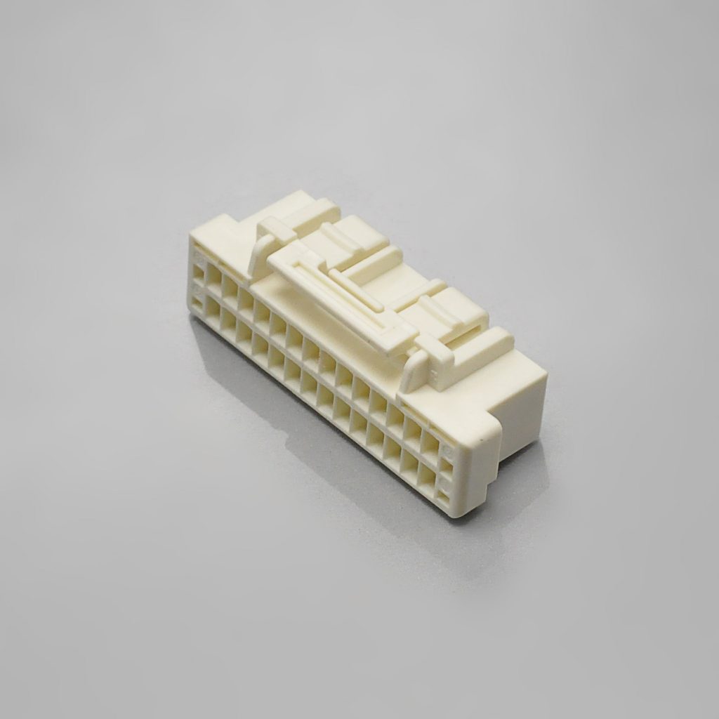
KR1507 dual row housing
Wire routing and strain relief: the figure nobody reprints
Molex publishes one number in this series that is easy to overlook and hard to work out for yourself: a minimum free wire length.
10.0 CABLE TIE AND / OR TWIST TIE LOCATION | CKT Size | Dim T Min. | |—|—| | 8-34 ckt | 35 mm | “The “T” dimension defines a “free” length of wire, or a length of wire that is not subject to significant bias by external factors such as a wire tie, wire twisting, or other means of bending or deforming of the wires that repositions them from their natural relaxed state or location where they enter the housing. Wires are to be dressed in such a manner to allow the terminals to float freely in the pocket. This dimension is general recommendation and may need to be adjusted for different wire gauges and wire type and insulation thickness and insulation material.”
35mm of unconstrained wire before the first tie-down, for the dual-row range. The reasoning behind it is stated in the same sentence: the terminals must be able to “float freely in the pocket.” A tie-down placed too close to the housing converts every harness movement into a side load on the terminal, and the terminal’s only defence is its 1.0 kgf retention in the housing.
Note the phrasing “general recommendation and may need to be adjusted for different wire gauges and wire type and insulation thickness and insulation material.” This is a starting figure, not a tolerance — and it is the kind of design guidance that tells you Molex has seen this failure in the field.
The rest of Molex’s usage notes are a strain-relief checklist
Molex devotes the last three pages of the specification to 27 numbered usage notes, and several of them are specifically about the mechanical environment rather than the connector:
“Please do not use the connector in a condition where the wire, the printed circuit board, or the contact area is experiencing a sympathetic vibration of wires and printed circuit board, and constant movement of devices. This may cause a defect in the contact due to the contact area being worn down. Therefore, please fix wires and printed circuit board on the chassis, and reduces sympathetic vibration.” (note 13)
“The cable assembly should not have a constant stress or pulling force applied on it when it is in the mated condition. This phenomenon may damage the contact area or wiring area (crimping). Therefore, when designing the wire positioning, please ensure that there is enough length of wire to avoid stress on the connector.” (note 22)
“Please do not use the connector alone to provide mechanical support for the printed circuit board (PCB). Please ensure that there is a fixed structure on the phone chassis or other component support for the PCB.” (note 19)
“Please do not do work that the load hangs in the connector like the carrying of the substrate etc. with the connector engages.” (note 15)
“After mated the connector, please do not allow the printed circuit boards to apply pressure on the connector in either the pitch direction or the span direction. It may cause damage to the connector and may crack the soldering.” (note 20)
Those five notes describe the same underlying requirement: the connector is a signal path, not a structural element. The lock is rated at 3.0 kgf, and that rating assumes the harness is supported so the lock is not carrying the assembly’s weight. On a 2×20 connector with a stiff bundle attached, the gap between “the lock is rated for 3 kgf” and “the lock is carrying 3 kgf every time the unit is handled” is entirely a harness-design question.
Two more notes that save rework:
“When extracting a crimp terminal from the housing using a jig, it may deform the housing lance and therefore reduce the terminal retention force after re-inserting of the terminal. Therefore, please ensure to use a new housing after repairing the crimp terminals.” (note 25)
Do not re-use a housing after pulling a terminal out of it with a jig. The retention you are relying on — 1.0 kgf minimum — is produced by a plastic lance that has been deformed by the extraction. A new housing costs a fraction of a field failure.
“The applicable wire for this connector, in principle, is tin-plated copper stranded wire. Please consult us and evaluate it in advance when using other wires.” (note 23)
Tin-plated copper stranded wire is the qualified construction. Solid-core, silver-plated, or any other construction needs a separate evaluation.
And one note about what the connector is protecting you from
The system is qualified with a discontinuity limit of 1.0 microsecond maximum during both vibration (2 hours per axis at 1.52mm peak-to-peak) and mechanical shock (50G, 11ms half-sine). That is a genuine electrical-continuity criterion under excitation, not a “no visible damage” inspection — and combined with the tuning-fork contact, it is the mechanical justification for choosing this family over a friction-lock alternative in a vibrating product.
KR1507 single row right-angle wafer
Cross-reference checklist: ten things to verify before you substitute
Work through these in order. Each one corresponds to a specific difference or contradiction identified in this guide.
| # | Check | Why |
|---|---|---|
| 1 | Write down the current figure for your wire gauge and your circuit count | Molex publishes 3.0A, 2.0A, 1.5A and 1.0A for this system at different gauges and circuit counts. Use the derating table, not the headline. |
| 2 | Confirm which wire gauge your design uses | The KR1507 covers AWG #24–28 with insulation 0.78–1.28mm. AWG #30 and insulation below 0.78mm are inside Molex’s range and outside the KR1507’s. |
| 3 | Decide single row or dual row, and get the row digit right in the part number | C1507RS1… / C1507VS1… are single row; C1507RS2… / C1507VS2… are dual row. One digit apart, different housing. |
| 4 | Ask which dual-row current rating is controlled: 2A or 1.5A | PS-KR1507-02 §4.0 says 2A (24AWG); the dual-row drawing says 1.5A. Get it in writing before you put either on a drawing. |
| 5 | Use 20mΩ for contact resistance and 500MΩ for insulation resistance | The single-row page says 30mΩ and the dual-row page says 100MΩ. Both contradict the specifications, and the specifications match Molex. |
| 6 | Decide whether you need the full environmental suite | The dual-row document includes 60°C humidity, 48-hour salt spray and SO₂/NH₃ gas. The single-row document does not. If your qualification file needs them, specify dual row or ask. |
| 7 | Check the insertion force at your position count | The rule is 0.33 kgf per circuit (plus 0.02 kgf withdrawal). A 2×20 dual row is 13.20 kgf — plan the mating method, not just the part. |
| 8 | Confirm the 34-circuit force row if you use 2×17 | It is the one row where Molex’s and KONNRA’s published figures diverge. |
| 9 | Measure your wire’s insulation O.D. | The window is a tight 0.78–1.28mm, and the crimp height window is only 0.10mm wide. An oversized insulation will not close to spec. |
| 10 | Cite the specification PDF, not the web page | The dual-row product page exists at two URLs, and several page figures contradict the controlled documents. PS-KR1507-01 (single row) and PS-KR1507-02 (dual row) are the documents with numbers, editions and issue dates. |
A supplier who will answer items 2, 4 and 6 quickly and in writing is a supplier you can qualify. Those are the three where the answer is not already public in a form you can rely on.
Frequently asked questions from procurement and engineering
What is the actual current rating — 3A or 1.5A? Both, and neither is the number you should design to without two more pieces of information. Molex’s 3.0A headline is qualified as “minimum circuit size and maximum wire gauge” and marked “for reference only.” Molex’s formal dual-row specification rates it 2.0A at AWG #24, 1.5A at AWG #26, and 1.0A at AWG #28 and #30. The derating table tops out at 2.5A at 8 circuits on AWG #24, falling to 2.0A at 16 circuits or more. Design to your gauge at your circuit count.
Is the KR1507 a drop-in replacement for Molex CLIK-Mate 1.5? On the electrical and mechanical specification it is very close — voltage, temperature range, durability, contact resistance, insulation resistance, dielectric strength, temperature rise, all four retention figures, and thirteen of the fourteen rows of the force table all match exactly, and the environmental programme for the dual row mirrors Molex’s test for test. The limits are on the wire side: AWG #30 and insulation below 0.78mm are not covered, and one terminal serves both row configurations rather than two terminals across two wire ranges. Treat it as a documented cross-reference to be qualified, not as a pin-compatible drop-in.
Can I use one terminal for both single-row and dual-row builds? Yes. undefined is the terminal for both variants — both KONNRA product specifications list the identical part number. One crimp setup, one set of applicator settings, and one fewer part number to control. Note also that it is mechanically retained in the housing at 1.0 kgf minimum and inserted with no more than 1.0 kgf, so the same insertion check applies to both builds.
What is the lock strength, and how do I release it? 29.4N (3.0kgf) minimum to separate a correctly mated pair, tested at 25.4 ± 3mm/min. To release, grip the wires together, push the lock release bar with the lock protection wall, then pull out slowly. Do not simply pull.
Can I disconnect it while the circuit is live? No. Molex states that the product “is not designed for the mating and unmating of the connectors to be performed under the condition of an active electrical circuit” and warns of sparking and product damage. This applies to the KONNRA equivalent as well, since it is the same contact and lock geometry.
How many mating cycles does it have? 30 cycles, both suppliers, with the acceptance criterion that contact resistance stays at or below 40mΩ after the cycles (double the 20mΩ initial limit). The withdrawal force does not degrade over those cycles — KONNRA publishes initial and 30th-cycle values that are identical at every position count.
What is the minimum free wire length before a tie-down? Molex recommends 35mm minimum for 8–34 circuits, described as a general recommendation to be adjusted for wire gauge, wire type and insulation. The purpose is to let the terminals float freely in the pocket so the harness is not loading the lance that holds them.
What do I need for a first article inspection? Eleven measurable items, all published: crimp height (24/26/28 AWG), crimp width, insulation crimp width and height, crimp pull strength (3.63 / 2.27 / 1.36 kgf minimum), terminal insertion force (≤1.0 kgf), terminal retention (≥1.0 kgf), header pin retention (≥0.3 kgf), lock strength (≥3.0 kgf), contact resistance (≤20mΩ), and insulation resistance (≥500MΩ). Once you have built the harness, the mated contact resistance and the lock release force are the two that catch assembly problems.
Do I need a wafer, or is it board-in? The KR1507 is wire-to-board — you order a housing, terminals and a wafer. Wafers are available in SMT 180° (straight) and SMT 90° (right angle), in both single-row and dual-row versions. If your connector has no wafer and its housing is soldered directly to the board, you are looking at a board-in family such as the JST SZN / KR1502 rather than this one.
What are the lead time and MOQ? KONNRA can deliver complete connector set samples within 45 days. Connector production lead time is typically 2–3 weeks, and wiring harness assemblies are quoted separately. MOQ depends on the row configuration, position count and terminal type — send the specific configuration and it will be quoted against the actual part numbers.
Which standards does it carry? Molex’s CLIK-Mate 1.5 carries UL File Number E29179. KONNRA’s KR1507 specifications do not publish a UL or CSA file number. If your product requires a recognised component, ask for the certification status of the specific KR1507 part numbers you intend to use.
What is the difference between the KR1507 and the KR1506? Different originals. The KR1507 cross-references the Molex CLIK-Mate 1.5 — inner positive lock, 2–15 single row or 2×4–2×20 dual row. The KR1506 cross-references the JST GH 1.5 and covers 2–6 circuits. They share a 1.50mm pitch and an inner-lock philosophy and little else. See our JST SZN 1.5 connector guide for the board-in family, and our Molex PicoBlade guide for the 1.25mm class.
Start your cross-reference check
Send us the five things below and we will come back with a specific answer rather than a catalogue page:
- Your measured current per circuit, the number of circuits loaded at once, and your wire gauge
- Your wire: AWG, conductor construction and measured insulation O.D.
- Single row or dual row, and the position count you need
- Wafer orientation — SMT 180° (straight) or SMT 90° (right angle)
- The Molex part numbers you are replacing, or a photo of the mated pair from above
From that we can confirm the housing, terminal and wafer part numbers, the crimp specification, the insertion force at your position count, and — where a figure in our published material is ambiguous, such as the dual-row current rating — give you a written answer against the controlled specification.
- Request a quote — KR1507 pricing, MOQ and configuration for your row configuration, position count and wire gauge
- Request a sample — complete connector set samples delivered within 45 days
- Request a cross-reference verification — KR1507 against your specific CLIK-Mate part numbers, including wire gauge, insulation O.D. and position count
- Request the documents — single row: engineering drawing (PDF), specification PS-KR1507-01 (PDF), package specification (PDF); dual row: engineering drawing (PDF), specification PS-KR1507-02 (PDF), package specification (PDF)
- Request a crimp specification sheet — conductor and insulation crimp heights, widths and pull-strength requirements for 24, 26 and 28 AWG
- Request a vendor qualification pack — test capability summary, quality documentation and certification status
- Request assembled harnesses — KR1507 assemblies crimped and tested to the specification above
- Submit a drawing for review — we will flag any specification mismatch before you commit tooling
Contact KONNRA Electronics
- Phone: (86)-769-85449875
- Email: info@konnra.com
- Address: No.6 Nanchang South Road, Chijiao, Wangniudun, Dongguan, Guangdong, China
- Contact us
Orderable components — single row: Right Angle Wafer · Straight Wafer · Housing · Terminal — dual row: Dual Row Right Angle Wafer · Dual Row Straight Wafer · Dual Row Housing
➡️ Explore the full 1.5mm pitch range · Wire-to-Board connector category · JST connector cross-reference: 20+ series
Sources and method
This guide compares the original manufacturer’s published documentation with KONNRA’s own published documentation for the cross-reference part. Where the two disagree, both figures are shown and the discrepancy is stated rather than resolved by preference.
Original manufacturer (Molex) — CLIK-Mate 1.5:
- Molex Product Specification, CLIK-Mate 1.5 Wire-to-Board Connector System, Dual Row Vertical Tin-Plating SMT, document number 5031491000-PS, revision B, change no. 666482, revised 2021/05/14, 17 pages. Used for: series and part numbers (
5025790*00,5034290000,503149**0*,503154**9*); UL File Number E29179; §4.1 voltage (100V AC rms/DC); §4.2 rated current by wire size (2.0A @ #24, 1.5A @ #26, 1.0A @ #28 and #30) and applicable wires with insulation O.D.; §4.3 current derating table (8/16/26/34 circuits) and its five stated conditions; §4.4 temperature (−40°C to +105°C); §4.5 durability (30 cycles, tin plated); §6.1 electrical performance (contact resistance 20mΩ max, insulation resistance 500MΩ min at 250V DC, dielectric strength 500V AC rms / 1 min, contact resistance on crimped portion 5.0mΩ max, temperature rise 30°C max); §6.2 mechanical performance (crimp pull-out force by gauge, crimp terminal insertion force 9.8N max, crimp terminal retention 9.8N min, header terminal retention 2.94N min, housing lock strength 29.4N min, repeated insertion/withdrawal, vibration at 1.52mm P-P with 1.0 microsecond discontinuity, mechanical shock at 490 m/s²{50G}); §6.3 environmental performance (temperature cycling, heat resistance 105±2°C/96h, cold resistance −40±3°C/96h, humidity 60±2°C 90–95% RH/96h, salt spray 48±4 hours, SO₂ gas, NH₃ gas, solderability, resistance to soldering heat); §7 insertion/withdrawal force table (8–34 circuits, 1st/6th/30th); §8.1 reflow solder temperature 245°C maximum and the 280°C housing-surface note; §10 cable tie location and the 35mm Dim T minimum; §11 notes; §12 instructions upon usage, notes 1–27 including the positive-lock release procedure, the full-solder requirement, the stencil T=0.1mm / 100% aperture note, the prohibition on mating under live circuit, and the requirement to use a new housing after terminal repair. - Molex Core Signal Connectors Reference Guide, document number 987651-9152, “Wire-to-Board Signal Core Products, 0.80 to 2.50mm-Pitch Connectors”. Used for: the 3.0A / 100V headline for CLIK-Mate 1.5 with its footnote (“When using minimum circuit size and maximum wire gauge. Current (max.) is for reference only.”); the CLIK-Mate single-row and dual-row series and circuit sizes; and the lock type, circuit size, wire gauge, current and voltage figures for the other 1.50mm families (Pico-Lock 1.5, Pico-SPOX 1.5, Spot-On 1.5, Pico-EZmate HC) used in the pitch-class comparison table.
Cross-reference manufacturer (KONNRA) — KR1507 series:
- Product specification PS-KR1507-01, Edition A1, issued and revised 2022/2/26, Engineering Dept., Dongguan Konnra Electronics Co., Ltd — single row. Used for: part-number table (housing
H150701**2401A, terminalT15070PT0101A, wafersC1507RS1**11M0101PA/C1507VS1**11M0101RA); §3.0 materials and surface treatment; §4.0 ratings (100V AC/DC, 3A (24AWG), −40°C to +105°C, AWG #24–28 with insulation O.D. 0.78–1.28mm); §5.1–5.3 electrical performance; §6.1–6.6 mechanical performance including lock retention force 3.0 kgf (29.4N) min and the crimp specification; §7.1–7.11 environmental performance including the 40±2°C humidity test with 100MΩ min insulation resistance and the 24-hour salt spray; §8.0 insertion/withdrawal force table (2P–15P); §9.1/9.2 temperature profiles; §10.0 remark. - Product specification PS-KR1507-02, Edition A1, issued and revised 2022/5/26, Engineering Dept., Dongguan Konnra Electronics Co., Ltd — dual row. Used for: part-number table (housing
H150702**2401A, terminalT15070PT0101A, wafersC1507RS2**11M0101RA/C1507VS2**11M0101RA); §4.0 ratings (2A (24AWG)); §5.1–5.3 electrical performance; §6.1–6.6 mechanical performance; §7.1–7.13 environmental performance including the 60±2°C humidity test with 500MΩ min insulation resistance, the 48-hour salt spray, and the SO₂ and NH₃ gas tests; §8.0 insertion/withdrawal force table (2*4–2*20); §9.1/9.2 temperature profiles; §10.0 remark. - Engineering drawing, KR1507 series (single row), Ver A3, drawing numbers 1507H101-A-S (housing), 1507T101-A-S (terminal), 1507WVS101-A-S (SMT 180° wafer). Used for: the “3A (AWG #24) AC, DC” and “100V AC, DC” specification block; contact resistance 20mΩ max; insulation resistance 500MΩ min; withstanding voltage 500V AC/minute; the single-row housing dimension table (2P–15P) and the locked-position grouping (2P–3P and 4P–5P with one lock, 6P–15P with two locks); the terminal material, finish, applicable wire range and reel quantity (10,000 pcs); and the recommended PCB layout tolerance of ±0.05mm.
- Engineering drawing, KR1507 Dual Row series, Rev A1, dated 2022/05/10, drawing numbers 1507H201-A-S (dual-row housing), 1507WVS201-A-S (dual-row SMT 180° wafer), 1507WRS201-A-S (dual-row SMT 90° wafer). Used for: the 1.5A AC, DC current rating and 100MΩ/min insulation resistance published in the drawing specification blocks; the dual-row housing and wafer dimension tables (
2*4P–2*20P); the wafer material listing (PA9T insulator, copper-alloy contact and nail, 1µm minimum matte tin over nickel); and the ordering codesC1507VS2**xx11M0101RA/C1507RS2**xx11M0101RAwith the 204 =2*4Pnumbering note. - KR1507 product pages (single row, and the dual row at both of its published URLs) and KONNRA’s 1.5mm pitch index page. Used for: the page specification tables (single row 3A / 100V / 2–15pin; dual row 1.5A / 100V /
2*4–2*20pin); the page-level materials, insulation O.D., withstanding voltage, temperature range, contact resistance (single row 30mΩ, dual row 20mΩ), insulation resistance (dual row 100MΩ) and plating entries that are compared against the controlled documents; component and document download links; and the cross-reference positioning of the sibling 1.5mm series (KR1500, KR1501, KR1502, KR1506, KR1511) used in the comparison table.
Not published in any source reviewed: a mating-cycle rating for the KR1507 beyond the 30-cycle durability test; contact resistance on the crimped portion for the KR1507; a 30 AWG crimp specification or terminal for the KR1507; UL/CSA file numbers for the KR1507; a named applicator or die set for the KR1507 terminal; and package or reel quantities for the KR1507 wafers and housings. Where a KONNRA document does not include a test that Molex performs (notably the SO₂ and NH₃ gas tests on the single row), this is reported as not specified in the document rather than as a failure. The dual-row current rating and insulation resistance differ between KONNRA’s own specification and its own engineering drawing, and neither document states which is controlled — that question is flagged for written confirmation rather than resolved here.
Method note. Figures were taken from controlled documents where available and from published web pages only where no controlled document exists. Where a web page figure contradicts the controlled specification for the same product, the specification figure is reported as the one to design against and the divergence is listed explicitly. The dimensional tables were transcribed and differenced position by position; the 1.5mm per-position progression in the A dimensions was confirmed to hold across the single-row housing range, the dual-row housing range and the dual-row wafer range, and the single exception found in the dual-row wafer B dimension is reported as observed. The insertion and withdrawal force specifications were analysed as sequences rather than as isolated values; both suppliers’ published tables were found to follow a single linear rule of 0.33 kgf insertion and 0.02 kgf withdrawal per circuit, and the one row where the two suppliers diverge is reported with both published figures rather than summarised.