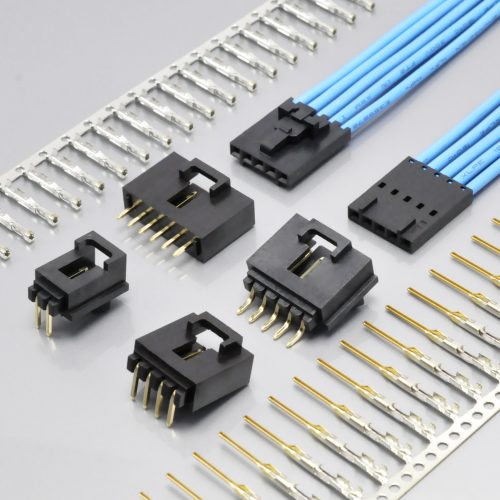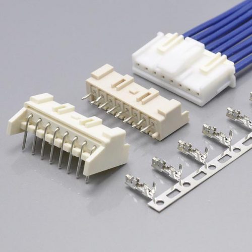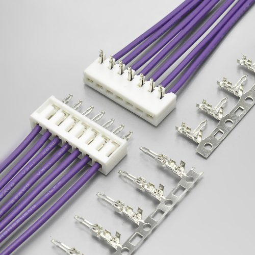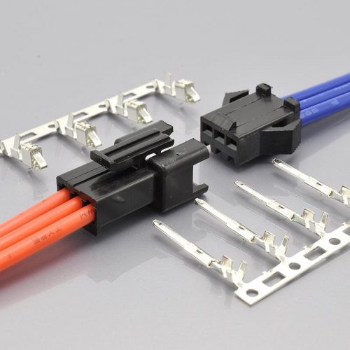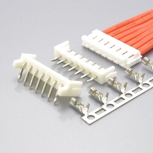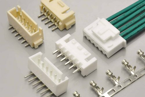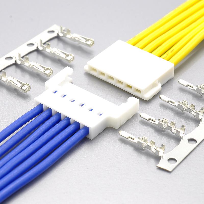
Quick answer: The Molex “MX2.0” 2.00mm wire-to-wire system is the 51005 / 51006 housing pair — 2.00mm pitch, single row, 2.0A per contact, −40°C to +105°C, 94V-0 resin — used with 50013 female and 50012 male crimp terminals. Molex has obsoleted it. Both series carry PCN 514359 (issued 2023-09-27, implemented 2024-10-31, change reason “OBS – Obsolete”, described as “Obsolescence without Replacement”), the part numbers still served are flagged Not Recommended For New Design, and Molex no longer publishes the series part list at all. The KONNRA KR2007 is the cross-reference equivalent and covers 2 to 16 circuits at the same 2.00mm pitch, 2.0A and −40°C to +105°C, with a PA66 UL94 V-0 housing and a published UL file number.
But before any of that, there is a labelling problem you have to know about, because it is the kind of problem that puts the wrong part on a line.
The two vendors use the words “male” and “female” in opposite directions for the housings. KONNRA’s Male Housing is the cross-reference for Molex’s 51005 Female / Receptacle Housing. KONNRA’s Female Housing is the cross-reference for Molex’s 51006 Plug Housing. Order by part number, not by the word — and read the section below before you send a BOM to anyone.
There is a second problem, and it is worse. Two files with the same filename are live on KONNRA’s own site right now, and they disagree about what the same part is called.

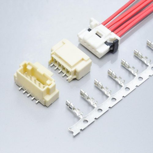
KONNRA KR2007 Series 2.0mm wire-to-wire plug connector, the cross-reference for the Molex 51005 and 51006 housing pair
At a glance
| Item | Molex 51005 / 51006 | KONNRA KR2007 |
|---|---|---|
| Status | Obsolete — PCN 514359, Not Recommended For New Design | Active |
| Pitch | 2.00mm | 2.00mm |
| Rows | 1 | 1 |
| Circuits documented | 2, 3 and 4 | 2 – 16 |
| Application | Wire-to-Wire | Wire-to-Wire |
| Current, max per contact | 2.0A | 2A AC/DC (at 24 AWG) |
| Voltage | 125V | 125V AC/DC |
| Temperature range | −40°C to +105°C | −40°C to +105°C |
| Housing resin | Polyester, flammability 94V-0 | PA66, UL94 V-0 |
| Housing colour | Natural | White |
| Terminal material | — | Phosphor bronze, tin over nickel |
| Terminal series | 50013 female / 50012 male | T2007FPT0101C / T2007MPT0101C |
| Applicable wire | — | AWG 24# – 28#, insulation O.D. 1.40mm max |
| Contact resistance | — | 20mΩ max |
| Insulation resistance | — | 1000MΩ min |
| Withstanding voltage | — | 500V AC / minute |
| Agency approval | UL E29179, CSA LR19980 | UL E482542 |
| Board-mounted half | None (wire-to-wire only) | None (wire-to-wire only) |
Three entries in that table need a note. Molex’s circuit list is only 2, 3 and 4 because that is what survives — with the series part list no longer published and the remaining inventory in the distributor channel, the sizes you can still document are the 2, 3 and 4 circuit housings in each series. If a 5-circuit 51005 ever existed, it is no longer documented by the manufacturer. KONNRA’s range runs continuously from 2 to 16 in single steps. And the KONNRA voltage line is the one the specification uses, 125V AC/DC — not a separate AC and DC figure.
The original is obsolete, and the replacement page does not name it
This is unusual enough to state plainly, because it inverts the usual direction of a cross-reference guide.
Molex is not “hard to find” here. Molex has withdrawn the product. The part-detail page for 51006-0200 carries five separate signals at once:
| Signal | What it says |
|---|---|
| Lifecycle banner | Not Recommended For New Design |
| PCN 514359, change reason | OBS – Obsolete |
| PCN 514359, change description | “As part of Molex’s ongoing strategy to optimize our product structure, Molex is obsoleting this product.” / “Obsolescence without Replacement” |
| PCN implementation date | 2024-10-31 |
| Series part list | “No Series Results Found” — “The parts in this series are not available for display in this list. Please contact Molex for more information on this series.” |
So a design that carries a 51005 or 51006 on its BOM is, today, a design with a sourcing problem — and the manufacturer’s own catalogue will not even list the series for you.
Now the part that is genuinely strange, and it is the reason this article exists.
The KONNRA page for the replacement says its Molex equivalent is “N/A”. The product listing in KONNRA’s own 2.00mm category reads KR2007 Equivalent To Molex N/A mx2.0 alternatives connector, and the page body opens with the fragment N/A connector, 2.00mm Pitch Crimp Terminal, Reel, for 51006 Housing. The cross-reference title and the cross-reference body contradict each other inside one page: the title says the Molex part is N/A, the body names 51006.
And the answer is available — just not on the page you land on. KONNRA publishes four separate component pages for the series, and every one of them names the exact Molex series it replaces:
| KONNRA component | KONNRA page | Molex series it names |
|---|---|---|
| Female Housing | components/2007-hm | 51006 Series |
| Male Housing | components/2007-hg | 51005 Series |
| Female Terminal | components/2007-mt | 50013 Series |
| Male Terminal | components/2007-gt | 50012 Series |
The naming on those four pages is not approximate and it is not aspirational — it matches the manufacturer’s own pairing documents exactly. Molex’s datasheet for the 51006 series states Mates With: 51005 Female Housing and Use With: 50012, and a Molex connector-kit bill of materials lists 50013-8100, “Female Crimp Terminal, Loose, for 2.00mm (.079″) Pitch, 51005 Receptacle” alongside 50012-8100, “Male Crimp Terminal, Loose, for 2.00mm (.079″) Pitch, 51006 Plug.” All four cross-references line up.
So the full cross-reference exists, is correct, and is published — behind four pages that the main product page never links to as a cross-reference, while the main product page’s own title says the answer is “N/A”. If you had looked at that page and concluded there was no defined Molex equivalent, you would have concluded wrongly, and you would have lost the one piece of information that makes the replacement safe to specify.
What to do about it
Use the component pages, not the product page title, and verify against the part numbers:
- Need the part Molex calls 51006 (their “Plug”)? Ask for the KR2007 Female Housing.
- Need the part Molex calls 51005 (their “Female Housing” / “Receptacle”)? Ask for the KR2007 Male Housing.
- Replacing Molex 50013 female terminals? Use
T2007FPT0101C. - Replacing Molex 50012 male terminals? Use
T2007MPT0101C.
The gender language is inverted between the two vendors
This is the single most expensive detail in the whole cross-reference, and it is not a typo in one place — it is systematic.
Molex defines the pair this way in its own catalogue data for 51006-0200:
| Molex field | Value |
|---|---|
| Description | 2.00mm Pitch Wire-to-Wire Plug Housing, 2 Circuits |
| Component Type | Plug |
| Gender | Plug |
| Mates With | 51005 Female Housing |
| Use With | 50012 |
KONNRA defines the same physical pair the opposite way round:
| KONNRA component | Molex series named | Molex’s own word for that series |
|---|---|---|
| Male Housing | 51005 | Female Housing / Receptacle |
| Female Housing | 51006 | Plug |
The housing gender word flips between the two vendors. The terminal gender word does not.
| Molex | KONNRA | Do the gender words agree? |
|---|---|---|
| 51005 Female / Receptacle Housing | H2007M Male Housing |
No — inverted |
| 51006 Plug Housing | H2007F Female Housing |
No — inverted |
| 50013 Female Crimp Terminal | T2007FPT0101C Female Terminal |
Yes |
| 50012 Male Crimp Terminal | T2007MPT0101C Male Terminal |
Yes |
So a Molex BOM that reads “51005 Female Housing + 50013 Female Terminal” converts to “KR2007 Male Housing + undefined Female Terminal” — the housing word inverts, the terminal word stays.
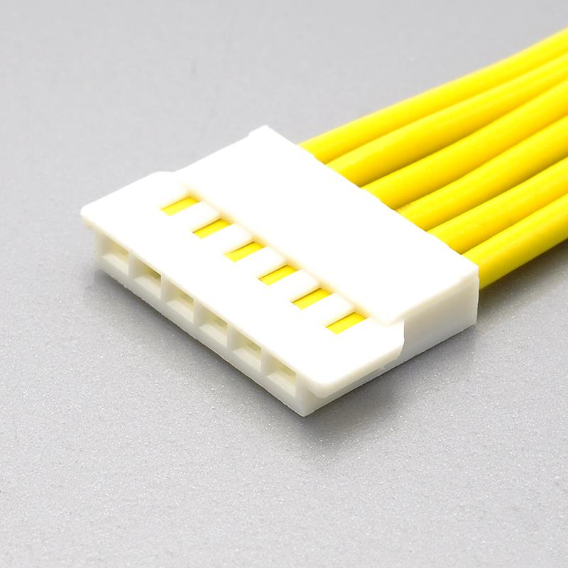
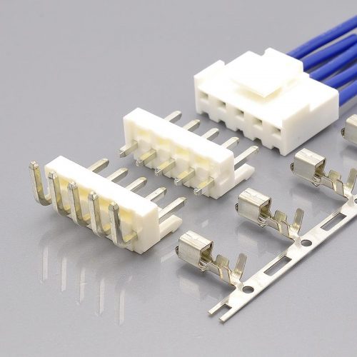
KONNRA KR2007 male housing, the cross-reference for the Molex 51005 female / receptacle housing

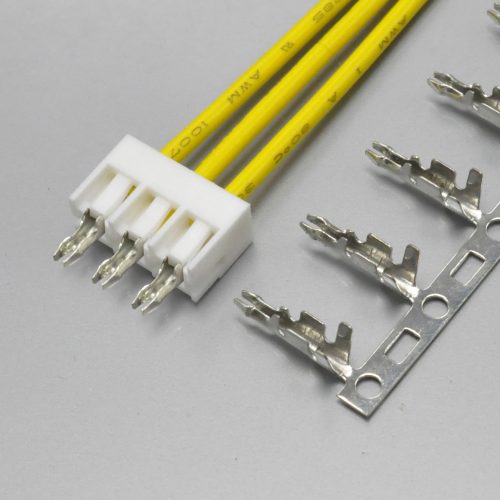
KONNRA KR2007 female housing, the cross-reference for the Molex 51006 plug housing
This is internally consistent, because within either system the two halves are opposite genders: KONNRA’s Male Housing takes the Female Terminal, and its Female Housing takes the Male Terminal. Nothing is wrong with the connector. What is wrong is the assumption that the word “male” means the same thing at both vendors. It does not.
The safe habit is to stop using the gender word as the identifier. Identify the part by the part number, by which Molex series it is compatible with, and by the drawing number — all three of which are unambiguous. H2007M***0101C is drawing 2007HM101-C-S; H2007F***0101C is drawing 2007HF101-C-S. Communicate those, not “the male one.”
Two live files with the same name disagree about the same part
This one is worth checking on your own screen, because it is the reason the paragraph above is worth reading twice.
KONNRA publishes a document titled KR2007-Series-Drawing.pdf. It is currently live at two different paths, and the two files are not the same file:
| Published path | File size | Linked from |
|---|---|---|
| 2023/09/KR2007-Series-Drawing.pdf | 466.6 KB | The four component pages |
| 2026/08/KR2007-Series-Drawing.pdf | 394.2 KB | The main product page |
Both are four pages. Both are marked REV.:A3. Both carry the same part number and the same drawing number on sheet 1 — H2007M***0101C, drawing 2007HM101-C-S. And they title that identical part differently:
| 2026/08 revision | 2023/09 revision | |
|---|---|---|
| Part No. | H2007M***0101C |
H2007M***0101C |
| Drawing No. | 2007HM101-C-S |
2007HM101-C-S |
| REV | A3 | A3 |
| Sheet title | Male Housing | Female Housing |
| Project | MX2.0 Air docking | MX2.0 Air docking |
The same part number, at the same revision number, is titled “Male Housing” in one live file and “Female Housing” in the other.
The part number itself settles it, and it settles it the way the newer file does. The suffix letter after H2007 is the gender: undefined is the male housing, H2007F is the female housing. The specification document agrees — section 2.0 lists H2007F1****01C and H2007M1****01C as the two housings — and the 2026/08 drawing is internally consistent with that. The 2023/09 file contradicts its own part number.
Use the 2026/08 revision. And if you are working from a printed or cached copy of the series drawing, re-pull it, because the copy you have may be the one that labels H2007M***0101C as the female housing.
One thing the drawing gets right that is worth copying
Both revisions spell out the tolerances the dimensions are held to, which is more than many series drawings bother to do:
| Decimal places | Tolerance |
|---|---|
| X.X | ±0.30 |
| X.XX | ±0.20 |
| X.XXX | ±0.10 |
| Angle | ±2° |
| Units | mm |
For a 2.00mm pitch part, that ±0.20 on a two-decimal dimension is the number you need when you are checking whether a replacement will sit in an existing housing opening. It is published, so use it rather than assuming a default.
Where the two systems match exactly
The overlap is real, and it covers the parameters that matter most for a drop-in review.
| Parameter | Molex | KONNRA KR2007 | Match? |
|---|---|---|---|
| Pitch | 2.00mm | 2.00mm | Exact |
| Number of rows | 1 | 1 | Exact |
| Application | Wire-to-Wire | Wire-to-Wire | Exact |
| Current, max per contact | 2.0A | 2A AC/DC at 24 AWG | Exact |
| Operating temperature range | −40°C to +105°C | −40°C to +105°C | Exact |
| Flammability rating | 94V-0 | UL94 V-0 | Exact |
| Board-mounted half | None | None | Exact |
The temperature range matching to both endpoints is the strongest single point in this comparison, because it is the parameter most often quietly narrowed on a drop-in part, and it is the one that shows up last — after the design is frozen. Both vendors publish −40°C to +105°C, and KONNRA’s specification confirms it independently in section 4.0 and again in each of the four engineering drawings.
Note also what is not in that table: nothing about the mating interface. Both documents describe a wire-to-wire system with no board-mounted half at all. There is no wafer, no header, no solder tab. If your design needs a board mount, this is the wrong series at either vendor, and the specification says so explicitly — section 2.0 of the KONNRA specification lists a “Wafer” row with the value None, and section 3.0 then devotes a full material block to wafer base, contact and solder tab, with every field reading N/A for both straight and right-angle versions. Read that block carefully: it is a section that exists only to say the section does not apply.
Where they differ
| Parameter | Molex 51005 / 51006 | KONNRA KR2007 | Nature of the difference |
|---|---|---|---|
| Lifecycle | Obsolete, PCN 514359 | Active | Commercial |
| Housing resin | Polyester | PA66 | Material substitution |
| Housing colour | Natural | White | Cosmetic |
| Circuit range documented | 2, 3, 4 | 2 – 16 | Range |
| Agency | UL E29179, CSA LR19980 | UL E482542 | Different file numbers |
| Voltage | 125V | 125V AC/DC | Consistent |
Two of these deserve more than a table cell.
The resin is a real substitution, and it is the difference a process engineer will notice first. Molex specifies polyester for the 51006 housing; KONNRA specifies PA66, a nylon. Both are rated 94V-0, so the flammability requirement is satisfied either way. But nylon and polyester do not behave identically — they differ in moisture uptake, in how they respond to reflow-adjacent temperatures, and in dimensional stability over humidity. For a wire-to-wire housing that never sees a soldering process this is usually not a problem. If your application has a specific resin called out by a qualified specification, that callout does not carry over, and it needs to be re-qualified rather than assumed.
The agency file numbers are simply different, not better or worse — UL E482542 for the KR2007 against E29179 for the Molex part, and Molex additionally holds CSA LR19980 where no CSA number is published for the KR2007. If your documentation requires a named CSA listing, that is a question to raise rather than an assumption to make.
Molex’s own documents disagree about whether the connector latches
You cannot settle this from the manufacturer’s literature, and you need to settle it, so here is exactly what is on the record.
| Source | What it says about the lock |
|---|---|
Molex part detail, 51006-0200, field Lock to Mating Part |
No |
Molex part detail, 51006-0200, field Gender |
Plug |
Molex datasheet for 51006-0400 (distributor copy) |
“Lock to Mating Part None“ |
| Molex connector-kit datasheet (76650-0229), describing 51005 against 51006 | The plug and receptacle “remain mated very strongly with locking tangs on both sides“ |
| Same kit datasheet | “The plug and receptacle mate with an audio click“ |
Distributor listing for 51005-0200 (third party) |
“2.00mm (.079”) Pitch Wire-to-Wire Plug Housing, Positive Lock, 2 circuits” |
Distributor listing for 51005 series (third party) |
“Mating lock: NA“ |
Molex’s structured data field says there is no lock. Molex’s own descriptive copy says there are locking tangs on both sides and an audible click. And a distributor listing for the same part says “Positive Lock” while another says “Mating lock: NA.”
An audio click and locking tangs on both sides are not decorative details — they are the difference between a connection that stays put under vibration and one that does not. And the “Lock to Mating Part” field is the field a design review reads.
Do not resolve this from the documents. Resolve it on the bench, or ask. It is a two-minute question with samples in hand and an unbounded risk if it is assumed.
The same question, on the KONNRA side, has a published partial answer
The KONNRA specification does not publish a lock force — but it tells you a lock contribution exists, in a way that is easy to miss.
Section 6.1, which covers insertion and withdrawal force, states the test method as inserting and withdrawing at 25.4 ± 3 mm per minute and then adds, in parentheses, “Excluding plastic detents.” The published insertion and withdrawal figures are therefore the contact system alone. Whatever the housing’s detent or latch contributes is deliberately not in the number, and its magnitude is not published anywhere in the document.
Practical consequence: the published insertion force (3.40 kgf at 2 circuits, rising to 6.20 kgf at 16) is a floor for what an operator feels, not the whole of it. If you are sizing an assembly station, a fixture, or a manual insertion task from the published table, you are under-estimating by whatever the detent adds — and the specification does not tell you how much that is. Ask for it, or measure it.
The circuit range, and the part-number code that tells you the size
The KR2007 runs 2 to 16 circuits in single steps — fifteen sizes, not only the even numbers. That is a wider published range than the surviving Molex documentation, which documents 2, 3 and 4.
The size is encoded in the part number, and the code is not the number you might expect:
| Field | Position | Values |
|---|---|---|
| Series and gender | H2007F / H2007M |
F = female housing, M = male housing |
| Circuit code | 3 digits | undefined = 2 circuits, undefined = 16 circuits |
| Insulator material | 2 digits | undefined = PA66 White (the only code published) |
| Suffix | 01C |
Fixed |
So a 2-circuit male housing in white PA66 is H2007M1020101C, and the 16-circuit version is H2007M1160101C.
Note the circuit code convention: the code is a literal undefined followed by the zero-padded circuit count. Two circuits is 102, sixteen is 116, and ten would be 110. This is worth stating because the specification and the drawing express the same part number two different ways, and only one of them can be decoded:
| Document | Mask as printed |
|---|---|
| Product specification, section 2.0 | H2007M1****01C |
| Engineering drawing, “Ordering Code” block | H2007M *** 01 01C |
Both describe the same 14-character number, but the specification’s wildcards straddle a field boundary — the four asterisks in H2007M1****01C cover the last two digits of the circuit code and both digits of the material code. You cannot construct a valid part number from the specification alone. The drawing’s form, which separates the three-digit circuit code from the two-digit material code, is the one to use.
And the ordering code offers exactly one option
The drawing’s insulator-material field publishes exactly one code, 01:PA66 White. That is the complete list. There is no second material code and no colour code.
This matters for one specific reason: the product page advertises capabilities this ordering code cannot deliver. The Overview section lists “Fault-proof interconnect” and describes connectors “equipped with error-proof interconnection systems, such as full keying and color-matching features.” With a single insulator material code and a single published colour, there is no colour to match. Keying and polarization may well be present; colour-coding is not available on this series as the ordering code defines it.
If your assembly procedure relies on colour to prevent cross-mating, this series will not support that method, and the ordering code — not the Overview paragraph — is the document to trust.
The force table: one exact law, one row that does not fit, a claim of zero loss, and one comparison worth making
This is the most informative single table in the specification, and it rewards reading closely. Section 8.0 publishes insertion force and withdrawal force for all fifteen circuit counts, at initial and after 30 insertion/withdrawal cycles. Units are kgf.
The insertion force is an exact linear law
| Circuits | 2 | 3 | 4 | 5 | 6 | 7 | 8 | 9 | 10 | 11 | 12 | 13 | 14 | 15 | 16 |
|---|---|---|---|---|---|---|---|---|---|---|---|---|---|---|---|
| I.F. max (kgf) | 3.40 | 3.60 | 3.80 | 4.00 | 4.20 | 4.40 | 4.60 | 4.80 | 5.00 | 5.20 | 5.40 | 5.60 | 5.80 | 6.00 | 6.20 |
Every one of the fifteen values is reproduced exactly by:
I.F. = 3.00 + 0.20 × (circuits)
Check it at both ends: 3.00 + 0.40 = 3.40 at two circuits, and 3.00 + 3.20 = 6.20 at sixteen. There is no exception anywhere in the table, which means the insertion force is a fixed 3.00 kgf of housing and latch engagement plus 0.20 kgf per contact, with no quantity discount and no friction coefficient changing with contact count.
That last point is the useful one. A linear law with a constant per-contact term means the insertion force you measure on a 2-circuit sample predicts the 16-circuit force exactly — you do not need to build and measure the worst case. Insertion force is therefore not the constraint that forces a circuit-count decision. If a limit is binding you, it will be withdrawal force or something else.
The withdrawal force follows a clean progression — with one row that breaks it
| Circuits | 2 | 3 | 4 | 5 | 6 | 7 | 8 | 9 | 10 | 11 | 12 | 13 | 14 | 15 | 16 |
|---|---|---|---|---|---|---|---|---|---|---|---|---|---|---|---|
| R.F. min, initial (kgf) | 0.32 | 0.33 | 0.34 | 0.34 | 0.36 | 0.37 | 0.38 | 0.39 | 0.40 | 0.41 | 0.42 | 0.43 | 0.44 | 0.45 | 0.46 |
| Predicted by 0.32 + 0.01 × (circuits − 2) | 0.32 | 0.33 | 0.34 | 0.35 | 0.36 | 0.37 | 0.38 | 0.39 | 0.40 | 0.41 | 0.42 | 0.43 | 0.44 | 0.45 | 0.46 |
Fourteen of the fifteen rows follow R.F. = 0.32 + 0.01 × (circuits − 2) to the last digit.
The 5-circuit row does not. It reads 0.34 kgf where the progression requires 0.35 kgf — and the increment that should have appeared between 4 and 5 has instead appeared between 5 and 6, where the table steps by the unusually large +0.02. The neighbouring rows are all +0.01. A single-cell typing error in one row of a published table is the most likely explanation, and it is the pattern to expect rather than a real change in the contact system at five circuits.
Practically: if you are quoting a withdrawal force for a 5-circuit part from this table, confirm it. Every other size can be interpolated with confidence.
And the table claims zero retention loss after 30 cycles — at every size
| Circuits | 2 | 3 | 4 | 5 | 6 | 7 | 8 | 9 | 10 | 11 | 12 | 13 | 14 | 15 | 16 |
|---|---|---|---|---|---|---|---|---|---|---|---|---|---|---|---|
| R.F. min, after 30 cycles (kgf) | 0.32 | 0.33 | 0.34 | 0.34 | 0.36 | 0.37 | 0.38 | 0.39 | 0.40 | 0.41 | 0.42 | 0.43 | 0.44 | 0.45 | 0.46 |
The after-30-cycles column is identical to the initial column at all fifteen circuit counts. Read literally, the specification is publishing zero measurable retention loss after 30 mating cycles — not a small loss, not a percentage, but no change at all, at any size.
That claim sits oddly against the rest of the same document, which does show degradation elsewhere. Section 7.1 runs a 30-cycle durability test and permits contact resistance to rise from 20mΩ max to 40mΩ max — a doubling. So the document expects the interface to change measurably with cycling, and records that change for resistance, but records none for withdrawal force.
There are two readings, and you should establish which one applies before relying on the column:
- The retention genuinely does not degrade over 30 cycles — plausible for a tin-plated contact at only 30 cycles, and a genuinely good result if true.
- The 30th-cycle column was populated as a copy of the initial column rather than from a separate measurement — in which case the column carries no information about retention at all.
The document does not say which. It is a legitimate question to put to a supplier, and it is worth asking, because the answer determines whether the withdrawal figures are a design limit or a nominal value. Note that other series in the same supplier’s 2.00mm range publish a non-zero retention loss in the same position of the same table, so the zero here is a deliberate entry rather than a house convention.
The terminal numbers put the whole force table in perspective
Two figures from section 6.0 reframe what the withdrawal numbers mean:
| Item | Specification | Value |
|---|---|---|
| Terminal insertion force | 6.2 | 1.5 kgf (14.7 N) max, per terminal |
| Terminal / housing retention force | 6.3 | 1.0 kgf (9.8 N) min, per terminal |
A single terminal is required to resist at least 1.0 kgf of axial pull before it leaves its housing. Now compare that against the force needed to unmate the complete connector:
| Circuits | Whole-connector withdrawal (kgf) | Aggregate minimum terminal retention (kgf) | Ratio |
|---|---|---|---|
| 2 | 0.32 | 2.0 | 6.3 × |
| 8 | 0.38 | 8.0 | 21 × |
| 16 | 0.46 | 16.0 | 35 × |
At every circuit count, the connector unmates at a fraction of the force its terminals can withstand. Even at sixteen circuits, the whole connector releases at 0.46 kgf against an aggregate retention of 16.0 kgf — a factor of roughly 35.
This is a good property and it is worth understanding rather than assuming. It means the mating interface is always the intended release point, terminal retention is never the limiting factor in a pull, and a wire will not pull out of a housing before the connector separates. It also means that a failure to unmate is not a retention problem — if a connector will not come apart, the cause is the detent or the mating interface, not the crimp.
Crimp and terminal data
The crimp table is short and specific. All three gauges use the same crimp widths; only the heights and the strength change.
| 24 AWG | 26 AWG | 28 AWG | |
|---|---|---|---|
| Conductor crimp width | 1.20 max | 1.20 max | 1.20 max |
| Conductor crimp height | 0.80 ± 0.05 | 0.70 ± 0.05 | 0.65 ± 0.05 |
| Insulation crimp width | 1.45 max | 1.45 max | 1.45 max |
| Insulation crimp height | 1.40 ± 0.05 | 1.25 ± 0.05 | 1.20 ± 0.05 |
| Crimp strength, min | 3.63 kgf | 2.27 kgf | 1.36 kgf |
| Stripping length | 1.6 – 2.2 mm | 1.6 – 2.2 mm | 1.6 – 2.2 mm |
Four things to take from that table.
The conductor crimp height step is not uniform. From 24 to 26 AWG it drops 0.10mm; from 26 to 28 AWG it drops 0.05mm. Do not assume a straight linear progression across the three gauges when setting up a crimp tool — the middle gauge is not the midpoint.
The insulation crimp step is not uniform either, and it does not mirror the conductor step. It drops 0.15mm from 24 to 26 AWG, then 0.05mm from 26 to 28 AWG. The two ladders are different ladders.
Crimp strength falls faster than conductor area. Going from 24 AWG to 28 AWG, the pull-out requirement drops from 3.63 kgf to 1.36 kgf — a factor of 2.67 — while the conductor cross-section drops by a factor of about 2.5. So the requirement tracks the copper, which is what you want to see: the specification is demanding roughly the same tensile strength per unit of copper across the range, not a flat force that would be trivial at 24 AWG and impossible at 28 AWG.
The stripping length is a single range for all three gauges — 1.6 to 2.2 mm. That is a 0.6mm window, which is wide enough to be practical on a bench tool and narrow enough to matter in a specification. Note it does not vary with gauge, so a single strip setting can serve the whole range.
And the reel quantity, which appears on both terminal drawings rather than in the specification: 13,000 pieces per reel for both the male terminal T2007MPT0101C and the female terminal T2007FPT0101C.
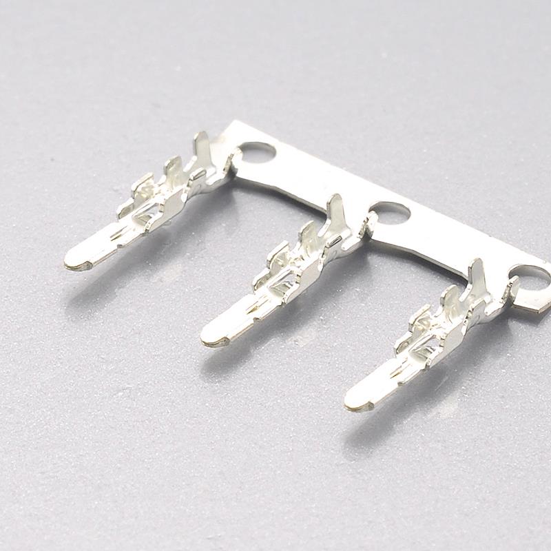
KONNRA KR2007 male terminal, the cross-reference for the Molex 50012 male crimp terminal
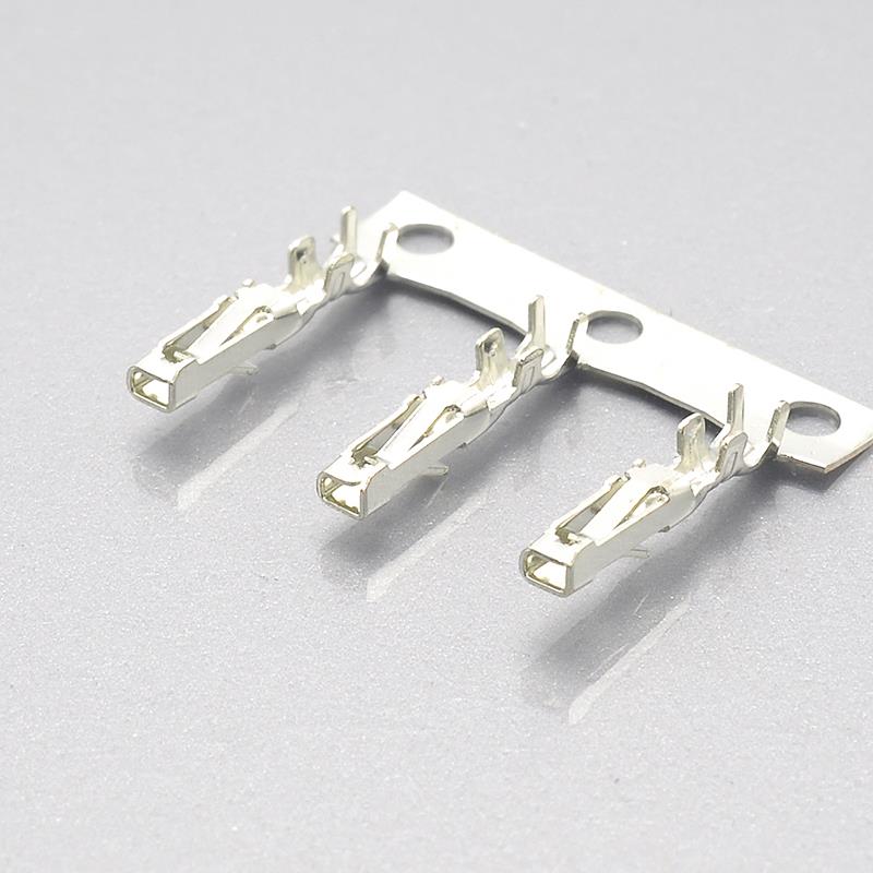
KONNRA KR2007 female terminal, the cross-reference for the Molex 50013 female crimp terminal
Materials, plating and the environmental programme
Materials
| Component | Material | Finish |
|---|---|---|
| Housing (both genders) | PA66, UL94 V-0 | — |
| Terminal (both genders) | Phosphor bronze | Tin plated over nickel |
| Wafer | N/A — the series has no wafer | N/A |
The plating callout is tin over nickel, not bare tin. The nickel underlayer is a barrier between the copper alloy and the tin, and it is the layer that keeps the contact from degrading when the tin diffuses into the substrate over time and temperature. On a part rated to +105°C this is the correct construction and it is stated explicitly rather than left to a general “tin plated” note.
The environmental programme
Nine tests, all referenced to EIA standards. The pattern is consistent: appearance must show no damage, contact resistance is allowed to double to 40mΩ max from the 20mΩ initial limit, and for the vibration and shock tests there is an additional discontinuity limit of 1 microsecond max.
| Test | Condition | Reference |
|---|---|---|
| Durability | 30 mating cycles at ≤ 10 cycles/minute | EIA-364-09C |
| Temperature rise | At rated current load | EIA-364-70B |
| Vibration | 1.5mm P-P, 10~55~10 Hz swept in 1 minute, 2 hours in each of X, Y and Z | EIA-364-28B |
| Shock | 490 m/s² (50g), 3 strokes in each of X, Y and Z | EIA-364-27B |
| Heat resistance | 105 ± 2°C for 96 hours | EIA-364-17B |
| Cold resistance | −40 ± 2°C for 96 hours | EIA-364-59 |
| Humidity | 40 ± 2°C at 90–95% RH for 96 hours | EIA-364-31B |
| Thermal shock | −40°C 30 min → room temp 5 min → +105°C 30 min → room temp 5 min, repeated for 5 cycles | EIA-364-32B |
| Salt spray | 35 ± 2°C, 5 ± 1% solution, 24 hours | EIA-364-26B |
Beyond the table:
| Result | Published limit |
|---|---|
| Temperature rise at rated current | 30°C max |
| Contact resistance, initial | 20mΩ max |
| Contact resistance, after every environmental test above | 40mΩ max |
| Discontinuity under vibration and shock | 1 microsecond max |
| Insulation resistance, initial | 1000MΩ min |
| Insulation resistance, after humidity | 100MΩ min |
The temperature rise limit of 30°C max is the number the 2A rating actually rests on, and it is worth pairing with it: 30°C above ambient, at −40°C to +105°C ambient, means the contact system is being permitted to reach 135°C in a +105°C environment. That is the design margin, stated.
And the humidity test derates insulation resistance by a factor of ten. The initial requirement is 1000MΩ min; after 96 hours at 90–95% RH it is 100MΩ min. That is not a contradiction — a post-conditioning limit is allowed to be looser than an as-supplied limit — but it is a real relaxation, it is ten-fold, and the product page does not mention it. The page’s General Specification table carries a single insulation-resistance row reading “1000MΩ Min” with no post-humidity figure beside it. If your application runs in high humidity, the 1000MΩ figure is the wrong number to design against, and the number you want is in section 7.7 of the specification.
What is not published
A guide is only useful if it says where the documents stop. These are the gaps I could establish.
| Not published | Where you would expect it |
|---|---|
| A UL or CSA file number in the specification or on the product page | The specification has no agency section. UL E482542 is published, but only on the four per-component pages — not on the product page and not in the specification. No CSA number is published anywhere for the KR2007. |
| A packaged, text-readable package specification | Package-spec_KR2007.pdf is published and is a four-page document, but it contains no extractable text — the content is vector or raster graphics. The only packaging figure available in text is the 13,000 pieces per reel on the two terminal drawings. |
| The force contribution of the detent | Explicitly excluded by section 6.1. Not given elsewhere. |
| Any colour or alternate material code | The ordering code publishes exactly one: 01:PA66 White. |
| Mating cycle life beyond 30 cycles | The durability test stops at 30. No longer-term figure is given. |
| Multi-contact current derating | The 2A rating is per contact at 24 AWG. No derating curve against circuit count is published, so the aggregate current a 16-circuit connector can carry is not stated. |
| Housing dimensions | The series drawing and per-component drawings are published as PDFs; I found no dimension tables in text form. Verify against the current drawing rather than a summary. |
| The Molex product specification | PS-51005-001-001.pdf is referenced from the Molex part-detail page and I was not able to retrieve it. All Molex figures quoted in this article therefore come from Molex’s own part-detail pages, Molex datasheet documents still in distribution, and distributor records — not from the withdrawn product specification. |
That last row is the honest limit of this article. The Molex side is quoted from what Molex still serves and what remains in distribution, and the series has been withdrawn, so treat every Molex figure here as “as last published” rather than “current.” The engineering answer to a withdrawn part is to qualify a replacement against your own requirements anyway, which is what the checklist below is for.
How to identify whether your connector is a Molex 51005 / 51006
If you have an unmarked 2.00mm wire-to-wire pair and no part number, these are the features that separate this system from the many other 2.00mm connectors on the market.
Confirm the family first:
- 2.00mm pitch, single row, wire-to-wire. There is no board-mounted half — no wafer, no header, no solder tab, on either mating half. If one side of your connector solders to a PCB, it is not this system.
- A male and a female housing that mate directly, each carrying crimped terminals, with the wire exiting in line with the mating axis. Two crimp terminals per circuit position — a female terminal
50013-equivalent in the 51005 half and a male terminal50012-equivalent in the 51006 half. - Two different terminal part numbers are required. If the same terminal part number works in both housings, you are looking at a hermaphroditic or single-terminal design, not this one.
Then confirm the size:
Count positions from 2 upward. Molex documents 2, 3 and 4. If your part has 5 or more positions it is either an undocumented Molex size or another series — and if it is a KR2007 it runs continuously to 16.
Then confirm the interface:
Per the Molex connector-kit datasheet, the 51005 and 51006 housings are 9.2mm and 10.8mm respectively and produce a mated length of 14.8mm, and the pair is described as mating with an audible click. The datasheet does not label which dimension those two figures describe, so use them as a description of relative size rather than as a datum to measure against. The click, if present, is the distinguishing feature — and note the caveat in the next section about whether the lock is real.
And once you have the number, use the number. The four KONNRA component pages, the specification section 2.0, and the drawing ordering code together resolve the part; the gender word alone does not, for the reasons in the inversion section above.
Where the KR2007 sits in the 2.00mm class
KONNRA’s 2.00mm pitch category is a large one — its Series filter enumerates nineteen codes. Within it, the Molex Connector Alternatives filter returns four series, and their positioning is worth reading carefully, because three of them are labelled almost identically and only one is the wire-to-wire pair:
| KONNRA series | Positioned against | Category |
|---|---|---|
| KR2007 | Molex 2.0mm wire-to-wire (51005 / 51006) | Wire-to-Wire |
| KR2000 | Molex MicroBlade | Wire-to-Board |
| KR2017 | Molex DuraClik | Wire-to-Board |
| KR2021 | Molex MINI50 | Wire-to-Board |
This is the most likely way to order the wrong part from this supplier. Three of those four series carry the string “mx2.0” in their title on the category page — “Molex MicroBlade mx2.0”, “Molex DuraClik mx2.0”, and “Molex N/A mx2.0” — and those three refer to three different Molex families. Only one of the three, KR2007, is the 51005/51006 wire-to-wire system. The other two are wire-to-board products against unrelated Molex families that happen to share the 2.00mm pitch.
So: “mx2.0” on this site means “Molex 2.00mm pitch”, not “Molex 51005/51006.” Filter on Wire-to-Wire and on the 51005 / 51006 / 50013 / 50012 numbers, not on the pitch nickname.
One more positioning note. Of the four Molex alternatives in the 2.00mm category, KR2007 is the only wire-to-wire one. If what you actually need is a board-mounted 2.00mm header to replace a MicroBlade or DuraClik, KR2007 is the wrong answer and its lack of a wafer is the reason — that is not a limitation of the KR2007, it is a different product for a different job.
Cross-reference checklist: ten things to verify before you commit
Work through these in order. The first three are where the money is.
- Order by part number, not by gender. KONNRA’s housing gender word is the opposite of Molex’s for the corresponding part.
H2007M(KONNRA “Male”) replaces Molex 51005, which Molex calls its Female housing.H2007F(KONNRA “Female”) replaces Molex 51006, which Molex calls its Plug. Confirm each line against the Molex series number before releasing a BOM. - Check which series drawing you are reading. Two files named
KR2007-Series-Drawing.pdfare live at two paths, both marked REV A3, and they title the same part number differently. The 2026/08 file is the one consistent with the part numbers; the 2023/09 file labelsH2007M***0101Cas the female housing. Re-pull the current file and re-issue any drawing derived from the older one. - Establish whether the assembly latches, on both sides of the cross-reference. Molex’s structured field says “Lock to Mating Part: No” while Molex’s descriptive copy says locking tangs on both sides and an audible click. KONNRA’s specification confirms a detent exists by excluding it from the force test, but does not publish its force. If the connection must survive vibration, this is a bench test, not a document review.
- Confirm the circuit count against the code, not the description. KR2007 circuit codes are
1plus the zero-padded count —102is 2 circuits,116is 16 — and Molex’s surviving documentation covers 2, 3 and 4 only. If you need 5 or more, you are outside the documented Molex range and should say so on your drawing. - Re-qualify the housing resin. Molex specifies polyester; KONNRA specifies PA66. Both are 94V-0, but a resin callout in your specification does not transfer. If moisture uptake, dimensional stability under humidity, or a qualified material list matters to your application, re-qualify rather than assume.
- Use the post-humidity insulation resistance in humid applications. The initial figure is 1000MΩ min, but section 7.7 permits 100MΩ min after 96 hours at 90–95% RH — a ten-fold relaxation that the product page does not mention.
- Treat the published insertion force as a floor. Section 6.1 excludes plastic detents, so the published 3.40 to 6.20 kgf is the contact system only. Whatever the latch adds is on top and is not published. Size fixtures and manual-insertion tasks with margin.
- Do not treat the 30-cycle withdrawal column as a measured value without confirming it. The after-30-cycles figure equals the initial figure at all fifteen circuit counts, which claims zero retention loss. The same document shows contact resistance doubling over the same 30 cycles. Ask whether the column was measured.
- Check the 5-circuit withdrawal figure specifically. Every other size follows 0.32 + 0.01 × (circuits − 2); the 5-circuit row reads 0.34 where the progression requires 0.35.
- Confirm the crimp settings per gauge rather than interpolating. Conductor crimp height steps by 0.10 then 0.05 across 24/26/28 AWG, and insulation crimp height steps by 0.15 then 0.05 — the two ladders differ and neither is linear. Stripping is 1.6–2.2 mm for all three.
Frequently asked questions from procurement and engineering
Is the Molex MX2.0 wire-to-wire series discontinued?
Yes. Both the 51005 and 51006 series carry PCN 514359 — issued 2023-09-27, implemented 2024-10-31, change reason “OBS – Obsolete” — and the part numbers I was able to open on each series both carry the Not Recommended For New Design flag. Molex’s part list for both series now returns no results at all. Note one internal inconsistency in Molex’s own record: the PCN description reads “Obsolescence without Replacement,” while the part-detail pages list a replacement part number with differences for each part. Either way, the published 51005/51006 part numbers are not orderable as new design content.
What is the difference between 51005 and 51006?
They are the two halves of one mating pair. Molex describes 51005 as the wire-to-wire receptacle / female housing and 51006 as the wire-to-wire plug housing. The 51005 half takes 50013 female crimp terminals; the 51006 half takes 50012 male crimp terminals. They are not interchangeable and you need one of each to make a connection.
Can I mix a KONNRA KR2007 housing with a Molex 51005 or 51006 housing?
The cross-references published by KONNRA name the specific Molex series for each component, and the specification and drawings are consistent with a mating pair. But the two vendors describe the system with inverted gender words, the Molex resin is polyester against PA66 on the KONNRA side, and — critically — Molex’s own documents disagree about whether the assembly latches. A mixed pair therefore stacks an unresolved latching question on top of a material substitution. Qualify a mixed pair on the bench against your own requirements; do not assume interchangeability from the cross-reference table alone.
How many circuits does the KR2007 come in?
Two to sixteen, in single steps — fifteen sizes. Molex’s surviving documentation covers 2, 3 and 4 circuits only.
What wire does it take?
AWG 24# to 28#, with a maximum insulation outside diameter of 1.40mm. The 2A rating is specified at 24 AWG, which is the largest gauge in the range. If you are running 28 AWG, the rated current is quoted against a different conductor and the ampacity question needs its own answer — the specification publishes the rating at 24 AWG only.
Does the KR2007 have a board-mounted version?
No. It is wire-to-wire only. The specification lists a “Wafer” row with the value None, and section 3.0’s wafer material block — base, contact and solder tab, for both straight and right-angle versions — is filled entirely with N/A. If you need a PCB half, you need a different series.
What is the UL file number?
E482542, published on the four per-component pages. It is not in the product specification and not on the main product page, which is why it can be hard to find. No CSA file number is published for the KR2007.
Is the 2A rating per contact or per connector?
Per contact, at 24 AWG. The specification does not publish a multi-contact derating curve, so the aggregate current a 16-circuit connector can carry is not stated in the documents and should be established from test data for your application rather than by multiplying.
Why does the specification exclude the detent from the force test?
Section 6.1 states the insertion and withdrawal figures are measured “Excluding plastic detents.” The published forces therefore describe the contact system only, and the latch contribution — which is what an operator feels — is additional and unpublished.
Start your cross-reference check
If you are holding a BOM with a 51005 or 51006 on it, the useful next step is not a catalogue search — it is a comparison against your actual requirement. Two things make that fast:
- Send the Molex part number and the circuit count. The KR2007 component numbering resolves circuit count and insulator code directly, so a specific replacement part number can be quoted against your existing line rather than against a family.
- Send the drawing you are working from, including the revision and which published path it came from. Given that two live files under the same name disagree about the same part, the revision you hold determines the answer.
The four cross-referenced components are the Male Housing (H2007M, replacing Molex 51005), the Female Housing (H2007F, replacing Molex 51006), the Female Terminal (T2007FPT0101C, replacing 50013) and the Male Terminal (T2007MPT0101C, replacing 50012) — 2 to 16 circuits, 2.00mm pitch, 2A AC/DC, 125V AC/DC, −40°C to +105°C.
Contact KONNRA with the Molex series number, your circuit count, and your working drawing, and the cross-reference can be confirmed against the part number rather than against the gender word.
- View the KONNRA KR2007 2.0mm wire-to-wire connector series
- Download the KR2007 product specification (PS-KR2007-01)
- Download the KR2007 series drawing
- Send an enquiry to KONNRA
Sources and method
Everything in this article is drawn from manufacturer documents and is cited so it can be checked. Where a figure could not be obtained, it is listed as not published rather than estimated.
KONNRA primary documents:
- Product specification PS-KR2007-01, Rev A1, issued 2022/2/26, 6 pages
- Series drawing KR2007-Series-Drawing.pdf, 4 pages, REV A3 — read at both published paths: the 2026/08 file (394.2 KB) and the 2023/09 file (466.6 KB)
- Package specification Package-spec_KR2007.pdf — published, 4 pages, no extractable text
- KR2007 product page
- KR2007 cross-reference listing
- The four component pages: 2007-hm, 2007-hg, 2007-mt, 2007-gt
- 2.00mm pitch category
- Per-component drawings: KR2007-HM_1, KR2007-HG_2, KR2007-MT_3, KR2007-GT_4
Molex primary documents:
- Part detail
51006-0200—molex.com/en-us/products/part-detail/51006-0200. Source of: the Not Recommended For New Design status, PCN 514359 with its 2023-09-27 / 2024-10-31 dates and “OBS – Obsolete” reason, the “Obsolescence without Replacement” description, “2.00mm Pitch Wire-to-Wire Plug Housing, 2 Circuits”, Component Type Plug, Lock to Mating Part: No, Material – Resin: Polyester, Number of Rows 1, Pitch – Mating Interface 2.00mm, Temperature Range – Operating −40° to +105°C, Current – Maximum per Contact 2.0A, Color – Resin: Natural, UL E29179 and CSA LR19980 - Part detail
51005-0200—molex.com/en-us/products/part-detail/51005-0200. Source of the same lifecycle signals, and of the replacement part number5055700201 - Molex part lists
molex.com/en-us/part-list/51005andmolex.com/en-us/part-list/51006— both return “No Series Results Found” - Molex datasheet for
51006-0400(distributor copy, generated 2019-09-18) — source of Flammability 94V-0, Mates With: 51005 Female Housing, Use With: 50012, and “Lock to Mating Part: None” - Molex connector-kit datasheet for
76650-0229— source of the 51005 (9.2mm) / 51006 (10.8mm) / 14.8mm mated length figures, the “audio click”, and “locking tangs on both sides”, plus the bill of materials confirming 50013-8100 as the female crimp terminal for the 51005 receptacle and 50012-8100 as the male crimp terminal for the 51006 plug PS-51005-001-001.pdfis referenced from the Molex part-detail page; it could not be retrieved, so no figure in this article is quoted from it
Method notes:
Insertion and withdrawal force laws are derived from the section 8.0 table and stated as derived. The I.F. relation reproduces all fifteen published values exactly; the R.F. relation reproduces fourteen of fifteen, with the 5-circuit row named as the exception. The “zero retention loss” finding is a direct comparison of the two published columns, not an inference. The terminal-retention ratios in the comparison table are arithmetic on published figures (1.0 kgf min per terminal against the published whole-connector withdrawal force), and are presented as an implication of the published numbers rather than as a tested result.
The gender-inversion finding rests on two sources that were checked against each other: KONNRA’s four component pages naming 51006, 51005, 50013 and 50012, and Molex’s own designation of 51006 as the Plug, 51005 as the Female Housing, 50012 as the male crimp terminal and 50013 as the female crimp terminal.
Corrections are welcome and will be made. If a figure here disagrees with the current revision of a manufacturer document, the manufacturer document is right and this article should be corrected against it.