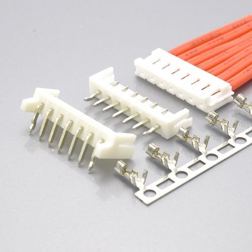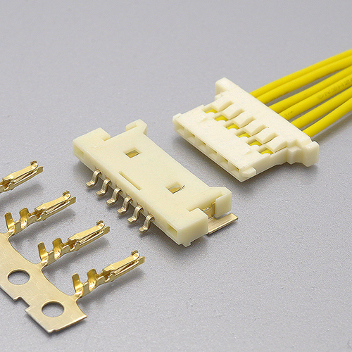
Quick answer: Molex PanelMate is Molex’s 1.25mm-pitch, single-row, wire-to-board connector system, built as a receptacle housing (51146 series) that mates with a low-profile SMT header (53779, 53780 and 55063 plug assemblies) using 50641 or 50753 crimp terminals. Molex rates it 125V AC (RMS)/DC and 1.0A maximum per contact, over an operating temperature range of −40°C to +85°C, for AWG #28, #30 and #32 wire — with a maximum insulation outside diameter of φ0.9mm for #28 and #30, but only φ0.55mm for #32. Its defining feature is height: Molex positions it as the lowest-profile fully-shrouded wire-to-board system in its range, at 1.03mm, 1.3mm or 1.85mm depending on plug assembly, and describes the dielectric strength test as 250V AC (RMS) for one minute. Despite the name, Molex’s own part data records Panel Mount: No — “PanelMate” refers to flat panel displays, not to a panel-mounting (bulkhead) connector. The KONNRA KR1253 series is documented as the cross-reference equivalent, offered as three separately orderable components: a right-angle SMT wafer, a housing and a terminal.
At a glance
| Common trade name | Molex MX1.25 · Molex 1.25mm · “PanelMate” |
| Official Molex product family | PanelMate (1.25mm pitch) — a separate family from PicoBlade 1.25mm |
| Molex wire-side series | 51146 — “PanelMate Wire-to-Board Receptacle Housing, Ultra Low Profile” |
| Molex board-side series | 53779 · 53780 · 55063 plug assemblies (headers); distributors also list 55178 |
| Molex crimp terminals | 50641 (AWG #28–30) · 50753 (AWG #30–32) |
| Pitch | 1.25mm |
| Configuration | Single row, wire-to-board |
| Circuits | Molex 53780 part list lists 2, 3, 4, 5, 6, 7, 8, 9, 10, 14, 15 and 20; KONNRA documents 2–15, 20 and 30 |
| Voltage rating | 125V AC (RMS)/DC (both sides) |
| Current rating | 1.0A maximum per contact (Molex) · 1A (KONNRA) |
| Applicable wire | AWG #28, #30, #32 |
| Insulation O.D. | φ0.9mm max (#28, #30) · φ0.55mm max (#32) — Molex; 0.6 to 0.9mm — KONNRA |
| Contact resistance | 20mΩ max initial (both sides) · 5mΩ max crimped portion (Molex) |
| Insulation resistance | 100MΩ min (both sides) |
| Dielectric strength | 250V AC (RMS), 1 minute (Molex) |
| Operating temperature | −40°C to +85°C (Molex) · −40°C to +105°C (KONNRA) |
| Durability | 30 cycles (Molex product specification) · 50 cycles (Molex part data for the 53780 header) · 30 cycles (KONNRA) |
| Profile height | 1.03mm / 1.3mm / 1.85mm by plug assembly (Molex PS) · 1.90mm maximum described height on molex.com part data · 1.90mm minimum height (KONNRA) |
| Contact material | Phosphor Bronze (both sides) |
| Plating | Molex: gold with 0.200µm min mating / 3.000µm min termination on the 53780 header; 0.203µm min on terminal 50641. KONNRA: Tin or Gold flash over Nickel, no thickness published |
| Retention | Friction lock — Molex part data records Lock to Mating Part: No for the 53780 header; KONNRA describes friction locks plus shell hooks |
| Panel mount | No — per Molex part data for the 51146 housing |
| Standards | Molex UL E29179 · CSA LR19980; KONNRA UL E482542 |
| Lifecycle status | 51146 housing: Not Recommended For New Design; 53780 header: Obsolete |
| KONNRA equivalent | KR1253 |
“—” indicates the parameter is not stated in the manufacturer documentation reviewed for this guide.
Is “Molex MX1.25” the same as PanelMate?
This is where most cross-references go wrong, so it is worth settling first.
“MX1.25” is not a Molex product name. The string is trade shorthand built from the 1.25mm pitch, and at 1.25mm Molex sells more than one family. PanelMate is one of them; PicoBlade is the other, and they are different connector systems that do not mate.
| Molex PanelMate | Molex PicoBlade | |
|---|---|---|
| Pitch | 1.25mm | 1.25mm |
| Molex wire-side series | 51146 | 51021 |
| Configuration | Wire-to-board | Wire-to-board and wire-to-wire |
| Circuits | up to 20 in the 53780 part list | 2 to 15 |
| Rated current | 1.0A | 1.0A (0.8A at AWG #32) |
| Voltage | 125V | 125V |
| Contact design | Blade-type pin, shell hooks, friction lock | Two-point contact, friction lock |
| Profile | 1.03 / 1.3 / 1.85mm by plug assembly | Not positioned as an ultra-low-profile system |
| Position in the range | Lowest-profile fully-shrouded wire-to-board system from Molex | The mainstream 1.25mm workhorse |
The practical consequence: if your design was released against a PanelMate part number, do not accept a PicoBlade cross-reference as equivalent — even though the pitch, the voltage rating and the 1.0A per-contact figure are identical on paper. The board-side footprints are different, the mating interfaces are different, and the low-profile geometry that PanelMate exists to deliver is not reproduced by PicoBlade.
Rule of thumb: at 1.25mm, confirm the Molex series number on the drawing before you cross-reference anything. Molex alone runs PanelMate (51146), PicoBlade (51021 / 53048), MSTB-family equivalents and Pico-EZmate at 1.20mm — and none of them mate with each other.
What Is the Molex PanelMate Connector?
Molex describes PanelMate as offering “the lowest profile of any fully-shrouded wire-to-board system from Molex”, and states that “the PanelMate series of connectors was designed for Flat Panel Display Panels that require thin, low profile connectors”. The series features an SMT header with robust solder tabs and a solder-conducting SMT fillet tail design for secure PCB retention.
Molex’s own product specification for the family (document PS-51146-010) states its scope as “1.25mm PITCH WIRE TO BOARD SMT CONNECTOR”. That one line already tells you two things that matter: the connector is wire-to-board, and the board side is surface mount.
Three design choices define the series:
- Ultra-low profile. The family is sold as three plug-assembly heights — 1.03mm (55063), 1.3mm (53779) and 1.85mm (53780) — with molex.com describing the 53780 as a “1.90mm Height” part. That discrepancy between a document value (1.85mm) and a catalogue value (1.90mm) is normal for this family, and it is the reason a PanelMate footprint check belongs in your drawing review rather than in a datasheet summary.
- An SMT header with real PCB retention. Both the product specification and Molex’s series description emphasise the solder tabs (“fitting nails” in the specification’s own wording) and the fillet tail geometry. The series exists because a 1.25mm connector on a thin display board has almost no room for a retention feature, so the retention has to come from the solder interface itself.
- A crimped wire side with a friction lock. The 51146 receptacle housing carries the terminals crimped onto AWG #28–32 wire; the housing is the half that is withdrawn when the assembly is serviced.
Key characteristics:
- 1.25mm pitch, single row, wire-to-board
- 1.0A maximum per contact, at 125V AC (RMS)/DC
- AWG #28, #30 and #32, with a gauge-specific insulation window
- −40°C to +85°C operating range, including terminal temperature rise
- Gold plating on the mating interface, tin on the termination interface
- SMT headers in three heights, all right-angle, all shrouded
- UL E29179 / CSA LR19980 on both the housing and the header
- Available in 2 to 20 circuits in the published 53780 part list
A short glossary, because this series uses specific terms
- Receptacle housing — the wire-side half. Molex’s PanelMate housing series is 51146.
- Receptacle terminal — the crimp contact that goes into the housing. PanelMate uses two: 50641 for AWG #28–30 and 50753 for AWG #30–32.
- Plug assembly — Molex’s name for the board-mounted header. The PanelMate range is 53779, 53780 and 55063.
- Solder tab / fitting nail — the metal tab at the end of the header that solders to the PCB and carries the mechanical load. In this family it is the primary retention feature.
- Friction lock — retention by friction between the housing and the header, with no separate latch to release. Molex’s part data for the 53780 header records Lock to Mating Part: No, which is consistent with a friction-only interface.
- Blade-type pin — the header pin geometry. KONNRA’s documentation states that the blade design reduces the risk of damage during mating.
- Panel mount — a connector designed to be fastened through a chassis or enclosure panel. Molex records Panel Mount: No for this family. See the dedicated section below.
- Insulation O.D. — the outside diameter of the wire’s insulation, quoted by Molex per wire gauge on this series. The crimp barrel must match it.
- Coplanarity — the flatness of the header’s solder tails. Molex specifies this only for the unmounted part.
- Hot-mating — mating or unmating while current is flowing. Molex explicitly excludes it on this series.
Molex PanelMate and KONNRA KR1253 Specifications
| Parameter | Molex PanelMate (Molex documentation) | KONNRA KR1253 (KONNRA documentation) |
|---|---|---|
| Pitch | 1.25mm | 1.25mm |
| Row configuration | Single row (1) | Single row (1) |
| Connection type | Wire-to-Board | Wire-to-Board |
| Circuits | 53780 part list: 2, 3, 4, 5, 6, 7, 8, 9, 10, 14, 15, 20 | 2 to 30 (drawings: 2–15, 20, 30) |
| Voltage rating | 125V AC (RMS)/DC | 125V AC/DC |
| Current rating | 1.0A max per contact | 1A (rated at 28 AWG) |
| Applicable wire | AWG #28, #30, #32 | AWG 28# to 32# |
| Insulation O.D. | φ0.9mm max (#28, #30) · φ0.55mm max (#32) | 0.6 to 0.9mm |
| Contact resistance | 20mΩ max initial · 5mΩ max crimped portion | 20mΩ max (spec PDF and drawings) |
| Insulation resistance | 100MΩ min (500V DC, 1 minute) | 100MΩ min (500V DC, 1 minute) |
| Dielectric withstanding voltage | 250V AC (RMS) / 1 minute | 500V AC / 1 minute in the specification PDF and terminal drawing; 250V AC / minute in the product-page table and housing drawing |
| Operating temperature | −40°C to +85°C (including terminal temperature rise) | −40°C to +105°C |
| Durability | 30 cycles (PS-51146-010) · 50 cycles (53780 part data) | 30 cycles |
| Temperature rise | 30°C max at rated current | 30°C max at rated current |
| Vibration | 1.5mm P-P, 10–55–10 Hz in 1 minute, 2 hours in each of X, Y, Z axes, cable fixed | Same amplitude, sweep and duration |
| Mechanical shock | 490 m/s² (50G), half-sine, 11ms, 3 shocks in each of 6 directions (18 total) | 490 m/s² (50G), 3 strokes in each of X, Y, Z |
| Housing material | Flammability 94V-0 | PA66 UL94 V-0 (Nylon 66 / PA9T on the wafer) |
| Contact material | Phosphor Bronze | Phosphor Bronze |
| Plating | Gold 0.200µm min mating / 3.000µm min termination (53780 header); gold 0.203µm min (terminal 50641) | Tin or Gold flash over Nickel — no thickness published |
| Retention | Friction lock; part data records Lock to Mating Part: No | Friction locks plus shell hooks |
| Panel mount | No | Not documented as a panel-mount part |
| Mounting | SMT, right-angle, three heights (1.03 / 1.3 / 1.85mm) | SMT 90° right-angle wafer |
| Assembly feature | Solder tabs / fitting nails; solder-conducting fillet tail | SMT solder tails for PCB retention; anti-flux penetration shield |
| Standards | UL E29179, CSA LR19980 | UL E482542 |
| Lifecycle | Housing Not Recommended For New Design; 53780 header Obsolete | Active |
| Mates with | 51146 housing ↔ 53779 / 53780 / 55063 plug assemblies | KR1253 wafer ↔ KR1253 housing |
Where the two documents agree: the 1.25mm pitch, the single-row configuration, the wire-to-board connection type, the 125V rating, the 1.0A per contact, the AWG #28–32 wire range, the 20mΩ maximum initial contact resistance, the 100MΩ minimum insulation resistance, the 30-cycle durability figure, the 30°C maximum temperature rise, the phosphor bronze contact material, the friction-lock retention concept, and the vibration and shock test conditions, which are written to the same amplitude, sweep rate and 490 m/s² (50G) shock level.
Where they differ: the operating temperature range, the circuits available, the dielectric withstanding voltage (and KONNRA’s internal inconsistency on that same field), the insulation diameter window at AWG #32, the plating thickness, the crimp pull-out force, the profile height and header count, and the lifecycle status. Each is covered below.
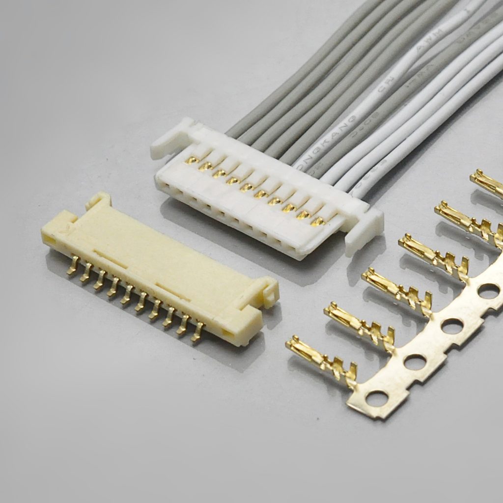
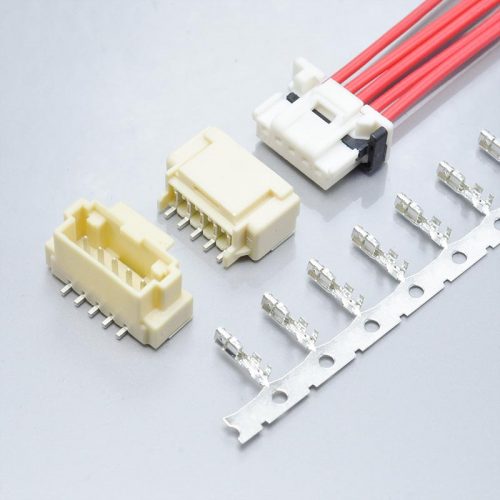
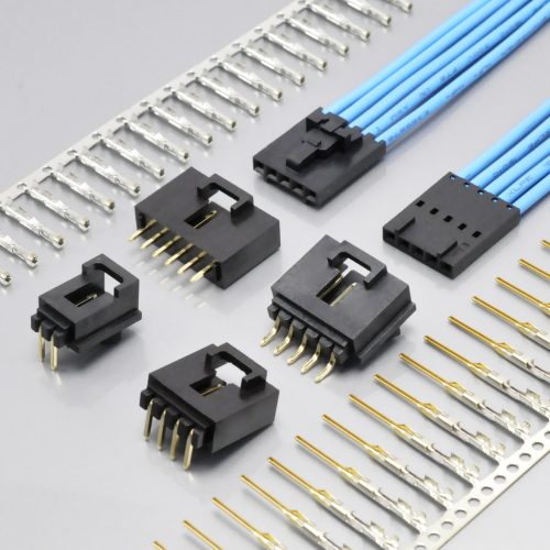
Figure 1 — KONNRA KR1253 series: 1.25mm pitch PanelMate wire-to-board connector
Figure 1 — KONNRA KR1253 series: 1.25mm pitch PanelMate wire-to-board connector
➡️ View the KONNRA KR1253 MX1.25 (PanelMate) Connector
Panel Mount: What “PanelMate” Actually Means
The name invites a specific and expensive mistake, so it is worth stating plainly.
PanelMate is not a panel-mount connector. Molex’s part data for the 51146 receptacle housing records Panel Mount: No. The name refers to the flat panel display market the series was designed for — Molex’s series description says the connectors “was designed for Flat Panel Display Panels that require thin, low profile connectors” — not to mounting through a chassis panel.
What the series actually is: a board-mounted, right-angle SMT header that sits flat against a display or main board, with a crimped wire harness plugging into it. Molex’s product specification opens with the scope “1.25mm PITCH WIRE TO BOARD SMT CONNECTOR”, and KONNRA’s own overview describes the KR1253 as designed “for flat panel displays with extra thin connectors”, with “SMT headers and SMT solder tails designed to provide strong PCB retention”.
Why the distinction matters for a cross-reference:
- If your design needs a bulkhead or chassis-panel feed-through, neither the original nor the cross-reference is the right part. You need a different family — and it is the panel requirement, not the pitch, that decides which.
- If your design is a display board with a wire harness crossing the enclosure, PanelMate is exactly the intended product: the harness passes through the enclosure opening as a wire bundle, and the connector stays on the PCB. Nothing in Molex’s documentation describes a PanelMate part that fixes to the enclosure itself.
- The retention load therefore lands on the solder tabs. Molex’s specification requires that all terminal tails and fitting nails are soldered, and warns that leaving any soldering area open risks terminal drop-out, pin-to-pin shorts, terminal buckling or the connector coming off the PCB. On a display board with a harness hanging off it, this note is the one that decides field reliability.
Ask the question directly on the enquiry: “does your application require the connector to be fastened to an enclosure panel?” If the answer is yes, the requirement is a panel-mount (bulkhead) connector, and the answer is not a PanelMate part number on either side.
Molex PanelMate = KONNRA KR1253: Part Number Cross-Reference
Molex’s PanelMate documentation splits the system across four series, and the product specification names the individual part numbers in each.
| Molex PanelMate component | Molex part number | KONNRA equivalent |
|---|---|---|
| Receptacle housing, ultra low profile | 51146-**00 (for example 51146-0500, 5 circuits) |
KR1253 housing — H125301****01A |
| Crimp receptacle terminal, AWG #28–30 | 50641-8*** |
KR1253 terminal — T12530PG0201A (gold) · T12530PT0101A (tin) |
| Crimp receptacle terminal, AWG #30–32 | 50753-8*** |
KR1253 terminal — same two documented part numbers |
| Plug assembly, H = 1.03mm | 55063-**19 (bulk) · 55063-**70 (embossed tape) |
Not documented |
| Plug assembly, H = 1.3mm | 53779-**19 (bulk) · 53779-**70 (embossed tape) |
KR1253 right-angle SMT wafer — C1253RS1**09*****RA (orientation to confirm) |
| Plug assembly, H = 1.85mm | 53780-**19 · 53780-**70 · 53780-**20 · 53780-**29 |
KR1253 right-angle SMT wafer — C1253RS1**09*****RA |
| Alternative header series | 55178 (listed by distributors as compatible) | Not documented |
The three orderable components on the KONNRA side, each with its own page:
| Component | KONNRA page | KONNRA states it is compatible with |
|---|---|---|
| Right Angle Wafer | Right Angle Wafer | 53779 / 53780 Series |
| Housing | KR1253 Housing | 51146 Series |
| Terminal | KR1253 Terminal | 50641 Series |
Note how the compatibility mapping lines up — and where it stops. The KONNRA housing is declared compatible with the 51146 housing series, the wafer with the 53779/53780 header series, and the terminal with the 50641 terminal series. That is a component-level cross-reference, which is what a second-source qualification needs. It does not cover the 55063 (1.03mm) or 55178 headers, and it does not name the 50753 (AWG #30–32) terminal series. If your design uses those, raise them explicitly rather than assuming the family mapping covers them.
Which crimp terminal goes with which wire
Molex splits the PanelMate terminal across two series, by wire range:
| Terminal series | Wire range | Documented termination features |
|---|---|---|
50641-8*** |
AWG #28–30 | Gold 0.203µm min mating and termination plating; wire insulation diameter 0.50–0.90mm (per molex.com part data for 506418041) |
50753-8*** |
AWG #30–32 | Documented in Molex’s PS-51146-010 part-number table; individual part data not reviewed for this guide |
Two consequences for the cross-reference:
- The two ranges overlap at AWG #30. Exactly as with most sub-2mm Molex systems, that overlap means the gauge alone does not select the terminal — the second question is which series your approved part number already names.
- KONNRA documents one terminal pair, not two. The KR1253 documentation publishes
T12530PG0201A(gold) andT12530PT0101A(tin), both with a stated wire range of AWG 28# to 32#. On the KONNRA side the gauge split that Molex makes across 50641 and 50753 is not published, so a design that depends on the specific crimp barrel geometry of one Molex series should ask for it directly.
On plating thickness, the two sides are not describing the same thing at the same resolution. Molex publishes micron figures: 0.200µm minimum gold on the mating interface and 3.000µm minimum on the termination of the 53780 header, and 0.203µm minimum on both interfaces of terminal 506418041. KONNRA publishes the finish but not the thickness — “Tin or Gold flash over Nickel” on the product page, the specification PDF and the drawings. The word “flash” is not a thickness specification on either side. If your part qualification names a micron value, that value has to be confirmed on the enquiry.
PanelMate vs Everything Else at 1.25mm
1.25mm is the most crowded pitch in the connector industry. Several manufacturers, at least six systems — and no two of them mate.
| Connector system | Pitch | Current | Voltage | KONNRA equivalent |
|---|---|---|---|---|
| Molex PanelMate | 1.25mm | 1.0A | 125V | KR1253 |
| Molex PicoBlade | 1.25mm | 1.0A (0.8A @ AWG #32) | 125V | KR1250 · KR1251 |
| Molex Pico-EZmate | 1.20mm | 1.5A | 50V | KR1200 |
| Hirose DF13 | 1.25mm | 1A | 150V | KR1256 |
| Hirose DF14 | 1.25mm | 1A | 150V | KR1255 |
| JST GH | 1.25mm | 1A | 50V AC/DC | KR1259 |
| KONNRA KR1252 (board-in) | 1.25mm | 1A | 125V | — |
| KONNRA KR1254 | 1.25mm | 1A | 200V | — |
Figures for the Hirose, JST and Pico-EZmate rows are taken from KONNRA’s published 1.25mm series data, which is consistent with those manufacturers’ own documentation; the PanelMate and PicoBlade rows are taken from Molex’s own documentation, cited in Sources and method.
Three things this table settles:
- “1.25mm” identifies a pitch, not a connector. Six of the eight systems here sit at exactly 1.25mm, from three manufacturers. KONNRA cross-references them as KR1253 (PanelMate), KR1250/KR1251 (PicoBlade), KR1255 (DF14), KR1256 (DF13) and KR1259 (JST GH). Getting the pitch right is the first step, not the answer.
- PanelMate and PicoBlade are the two Molex options at this pitch, and they are not interchangeable. Same pitch, same 125V, same 1.0A per contact — different series numbers, different footprints, different contact geometry. The choice between them is made by the profile height requirement, not by the electrical rating.
- The voltage rating separates these systems more than the current rating does. PanelMate and PicoBlade carry 125V; JST’s GH at the same pitch carries 50V. If your circuit runs above 50V, the GH family is out at any current — and PanelMate is the higher-headroom choice between the two Molex families for the same reason it was specified in the first place: it was built for display panels with higher bus voltages than a 50V logic interface.
Specification Differences to Verify Before You Cross-Reference
Ten points deserve attention before you sign off a PanelMate cross-reference. Each states which document each figure comes from, because on this family the two sides disagree in specific, checkable places.
- The operating temperature range is not the same, and it is the largest single difference. Molex rates PanelMate at −40°C to +85°C — stated in PS-51146-010 §3 and repeated in molex.com part data for both the
51146housing and the53780header. KONNRA documents −40°C to +105°C on its product page, in PS-KR1253-01 §4 and on all three drawings. That is a 20°C difference at the top end, and it is not a rounding detail: the two sides also run their heat-resistance tests at different setpoints — Molex at 85±2°C for 96 hours, KONNRA at 105±2°C for 96 hours. If your thermal analysis assumes 105°C capability because the replacement is specified that way, verify it against your own temperature-rise testing rather than reading it off the datasheet.
- The dielectric withstanding voltage is claimed differently — and KONNRA’s own documents disagree with each other. Molex specifies 250V AC (RMS) for 1 minute between adjacent terminals or ground, with a pass criterion of no breakdown (PS-51146-010 §4-1-3). KONNRA’s specification PDF §5.3 specifies 500V AC for 1 minute, and the KR1253 terminal drawing also shows 500V AC/minute. But the KONNRA product-page table and the KR1253 housing drawing both show 250V AC/minute. So: on this parameter the product page agrees with the original — 250V AC, both sides — while the specification PDF and terminal drawing claim double that. Do not quote 500V without resolving which document governs. Note also that the rated voltage — 125V — is the same on both sides, so this is purely a test-claim difference, not a rating difference.
- The KONNRA product page states contact resistance as 30mΩ Max, which contradicts KONNRA’s own specification. The product-page general specification table says 30mΩ Max. KONNRA’s PS-KR1253-01 §5.1 specifies 20 milliohms Max, measured by dry circuit at 20mV maximum and 100mA maximum, and all three KR1253 drawings show 20mΩ Max — as do KONNRA’s wafer, housing and terminal component pages. Molex specifies 20mΩ max initial. The product page is the outlier on its own side; the figure to work from is 20mΩ max, which matches the original.
- The insulation diameter window does not fully overlap at AWG #32. Molex specifies a gauge-specific window: φ0.9mm maximum for AWG #28 and #30, but only φ0.55mm maximum for AWG #32 (PS-51146-010 §3). KONNRA documents a single window, 0.6 to 0.9mm, with no gauge split, against a wire range that includes AWG #32. A wire that satisfies KONNRA’s lower bound at 0.6mm is outside Molex’s φ0.55mm maximum for #32 — so a #32 design cannot be validated against both documents at once. Note that KONNRA’s figure publishes a lower bound as well as an upper bound, so check both ends against your actual cable.
- Durability is 30 cycles on one Molex document and 50 on another — and KONNRA says 30. PS-51146-010 §4-3-1 specifies 30 mating cycles at a rate below 10 cycles per minute, after which contact resistance must remain within 40mΩ. molex.com part data for the
53780header states Durability (mating cycles max): 50. KONNRA’s PS-KR1253-01 §7.1 specifies 30 cycles at up to 10 cycles per minute with the same 40mΩ maximum criterion. So 30 cycles is the figure both sides substantiate, and the 50-cycle catalogue value needs confirming if your service model depends on it.
- The number of circuits available is wider on the KONNRA side, and KONNRA’s own drawings disagree about the top of the range. Molex’s
53780part list enumerates 2, 3, 4, 5, 6, 7, 8, 9, 10, 14, 15 and 20 circuits. The KONNRA housing drawing states 2~15, 20, 30, and the product page states 2–30. The KONNRA wafer drawing states “Circuits: 2~20,30”, which omits 15 and does not match the housing drawing. Treat 30 positions as beyond the published Molex header range and confirm both the exact count and which drawing governs.
- Crimp pull-out force is specified higher on the KONNRA side. Molex’s minimum crimp pull-out figures are 9.8N (1.0 kgf) at AWG #28, 4.9N (0.5 kgf) at #30 and 2.9N (0.3 kgf) at #32. KONNRA’s PS-KR1253-01 §6.5 lists crimp strength minimums of 1.36 kgf, 0.9 kgf and 0.7 kgf for the same three gauges. A higher minimum on the replacement is not automatically a problem, but it is a different test claim on a different crimp barrel, and it should be confirmed as applying to the wire you actually use.
- Terminal retention and pin retention are also specified higher by KONNRA. Molex specifies crimp terminal retention force at 4.9N (0.5 kgf) minimum and header terminal retention at 2.0N (0.2 kgf) minimum (PS-51146-010 §4-2-4, §4-2-5). KONNRA specifies terminal/housing retention 0.7 kgf (6.86N) minimum and pin retention 0.3 kgf (2.94N) minimum (§6.3, §6.4). Same direction as item 7 — the replacement claims more, on its own test method.
- Insertion and withdrawal force largely agree, with one anomalous row to check. Molex specifies insertion force at 2.1N (0.22 kgf) per circuit maximum and withdrawal at 0.2N (0.02 kgf) per circuit minimum. KONNRA’s PS-KR1253-01 §8.0 tabulates total force per circuit count, and at the low end it lines up exactly: 2 circuits → 0.44 kgf insertion maximum and 0.04 kgf withdrawal minimum, which is 0.22 and 0.02 kgf per circuit. The KONNRA table’s 15-position row shows withdrawal force of 2.30 kgf, against a pattern that would predict 0.30 kgf and a 16-position value of 0.32 kgf — this reads as a typographical error in the published table and should be confirmed rather than quoted.
- Plating thickness, wire construction and gas testing are documented by Molex and not by KONNRA. Molex specifies the gold thickness on the mating interface (0.200µm min on the 53780 header, 0.203µm min on terminal
506418041) and termination plating of 3.000µm min on the header. Molex also states that the applicable wire is, in principle, tin-plated copper stranded wire, and that other constructions require consultation and evaluation, and it specifies SO₂ gas (50±5ppm, 40±2°C, 24 hours) and NH₃ gas (40 minutes over 28% solution at 25mL per 1L) exposure tests. KONNRA’s KR1253 specification PDF lists no plating thickness, no wire construction and no gas tests. If your qualification includes any of those three, they are open items.
Two further environmental-test conditions worth lining up, because they are close but not identical. Molex’s humidity test runs at 60±2°C, 90–95% RH for 96 hours with insulation resistance allowed to fall to 10MΩ minimum afterwards, while KONNRA’s runs at 40±2°C, 90–95% RH for 96 hours with 100MΩ minimum. Molex’s salt spray runs 48±4 hours at 35±2°C with 5±1% NaCl; KONNRA’s runs 24 hours under the same concentration and temperature. And Molex’s temperature cycling is −55°C to +105°C, while KONNRA’s thermal shock is −40°C to +105°C. None of these is a defect — they are different test severities, and they decide whether a qualification can be carried over or has to be repeated.
Design Cautions Worth Carrying Into Your Review
Molex publishes an unusually long and specific note list for this family — thirty-seven numbered notes in PS-51146-010. They are not marketing; they are the failure modes the product is known to have, and they are the most useful part of the document for anyone designing this connector in or out. KONNRA does not publish an equivalent list, and its own overview adds two design features worth noting in the same breath: an anti-flux penetration design described as fully shielded, and a construction that prevents the connector from being inserted backwards.
- Do not mate or unmate under load. Molex states this product “is not designed for the mating and unmating of the connectors to be performed under the condition of an active electrical circuit”, and that doing so “may cause a spark and product defect”. If your service procedure disconnects this connector live, that procedure needs changing.
- Withdraw slowly, axially and straightly. Molex’s instruction is to hold the wires together lightly, put a finger on the lock, push the release bar with the flat of the finger until the lock is completely released, then withdraw. Angled or rough withdrawal “might cause damage to connector”.
- A continuous pulling or stress force must not be present when mated. Molex states this can damage the contact area, the crimp and the terminal lock. The design guidance is to leave enough wire length and slack that no tension reaches the connector.
- Use a new housing after extracting a terminal. Extracting a crimp terminal with a jig can deform the housing lance and “reduce the terminal retention force enormously” after re-insertion. Molex’s instruction is to fit a new housing when repairing crimp terminals.
- Mating alignment matters. Mate along the mating axis. If diagonal mating is unavoidable, lightly contact the external faces of the receptacle housing and the plug at under 10° to position them, then push straight in until fully mated.
- Respect the per-circuit rating, and the sum. Molex notes that the sum of the current across several circuits must not exceed the maximum allowable current — the per-circuit figure is not the whole answer.
- Do not wash the connectors. Molex states that any washing process may damage the product’s function.
- Avoid sympathetic vibration between the wires and the PCB. Molex’s guidance is to fix both wires and PCB to the chassis, so that sustained relative movement cannot wear the contact area and cause a defect.
- Do not carry the board by the harness while mated, and do not apply pressure in the pitch, span or rotational direction after mating — Molex states this may damage the connectors and crack the solder joints.
- Solder every terminal tail and every fitting nail. Molex warns that leaving any soldering area open risks terminal drop-out, pin-to-pin short circuits, terminal buckling, or the connector coming off the PCB.
- Expect the flatness specification to be a pre-mount specification. Molex requires PCB warpage, measured from one edge of the connector to the other, to be a maximum of 0.02mm, and states that coplanarity is assured only before mounting — there is no guarantee after mounting or after reflow.
- Air reflow is assumed; N₂ reflow needs separate evaluation. Molex states the product is intended for air reflow, and that nitrogen reflow requires separate evaluation because solder wicking can occur. Hand-soldering repair is specified at 370–400°C for a maximum of 5 seconds, with no excessive pressure and no excess solder or flux.
- Do not let the connector carry the board, and do not stack bare boards on it after mounting. Molex also requires consulting before designing to a modified board pattern, and before mounting on a flexible or other special PCB — the general performance verification was carried out on a glass-epoxy board.
The reflow profiles are close but not identical, and this is the one process parameter worth putting side by side. Molex specifies a peak of 250 +5/−0°C, 20–40 seconds at 230°C minimum, 90–120 seconds of preheat at 150–200°C, with a reflow count of 1 maximum. KONNRA specifies 5–10 seconds at a 255±5°C peak, 20–40 seconds at minimum 230°C and 90–120 seconds of preheat at 150–200°C. The preheat and time-above-liquidus windows match; the peak temperatures differ by roughly 5°C. Both manufacturers tell you to verify the profile on your own equipment and boards, and on this family that instruction is not boilerplate — the whole point of the product is a thin moulding sitting on a thin board.
Components and Configuration Options
The KR1253 is specified as three separately orderable components — a right-angle SMT wafer, a housing and a terminal. KONNRA’s component pages map each one to the Molex series it substitutes for, which is what makes a component-level cross-reference check possible.
Wafer (board-mounted header)
| Attribute | KONNRA documented value |
|---|---|
| Assembly type | Wafer |
| Compatible with | 53779 / 53780 Series |
| Orientation / mounting | SMT 90° right angle |
| Positions | 2P to 30P |
| Insulator | High temperature thermoplastics (drawing) · PA66 (component page) |
| Contact | Phosphor bronze |
| Solder nail / tab | Brass |
| Plating | Gold plated over Nickel |
| Part number pattern | C1253RS1**09*****RA |
| UL | E482542 |
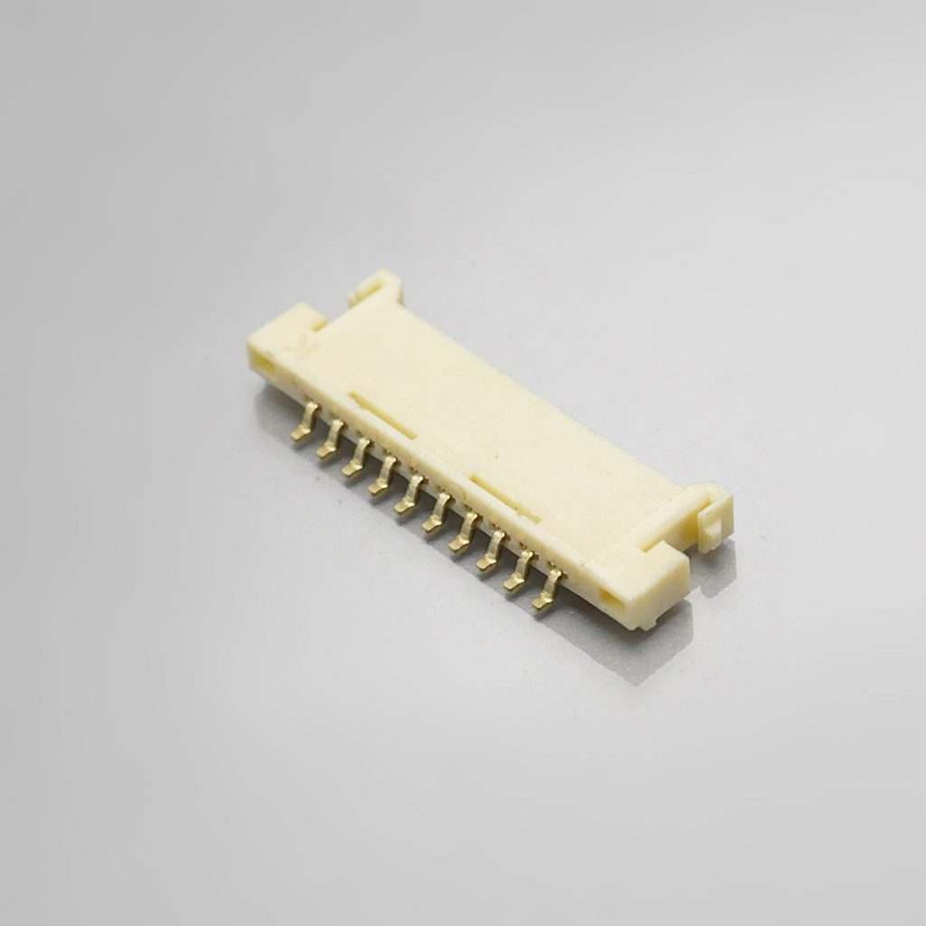
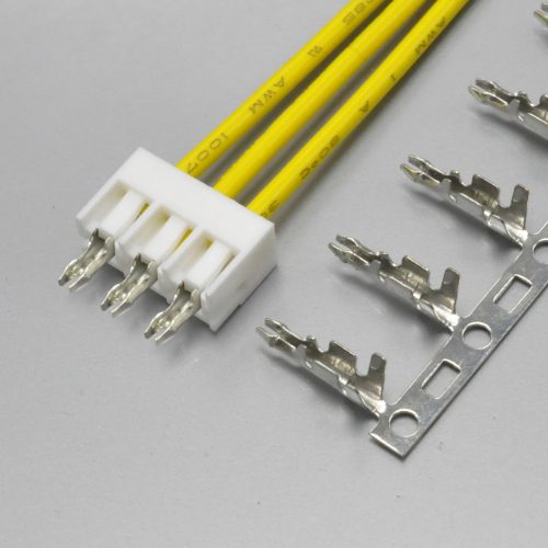
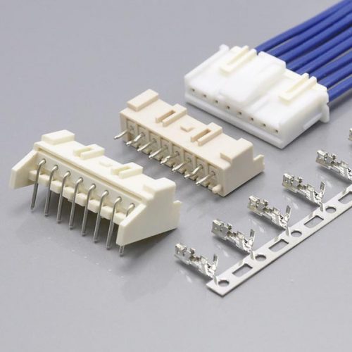
Figure 2 — KR1253 right-angle SMT wafer, the board-side half of the PanelMate interface
Figure 2 — KR1253 right-angle SMT wafer, the board-side half of the PanelMate interface
One documentation point to carry into your review. In PS-KR1253-01, the material table lists the wafer twice: once as “Straight (SMT 180°)” with the base, contact and solder tab all marked N/A, and once as “Right Angle (SMT 90°)” with PA9T base, phosphor bronze contact and brass solder tab. The KR1253 drawings describe the wafer as “SMT 90° WF” only. On the documentation reviewed, this series is specified as a right-angle SMT wafer; a straight SMT 180° variant is not substantiated by the material table. If your layout needs a vertical header, that is a question for the enquiry rather than an assumption.
Housing (wire side)
| Attribute | KONNRA documented value |
|---|---|
| Assembly type | Housing |
| Compatible with | 51146 Series |
| Positions | 2P to 30P |
| Material | PA66 UL94 V-0; the housing drawing states Nylon 66 UL 94V-0 |
| Colour | Beige (component page); the ordering code offers white, black and beige |
| Wire / cable size | 28# to 32# |
| Part number pattern | H125301****01A |
| UL | E482542 |
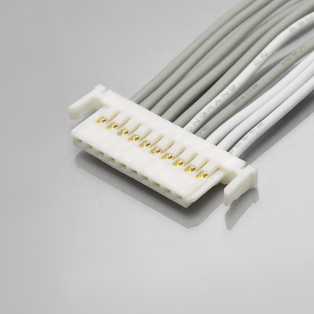
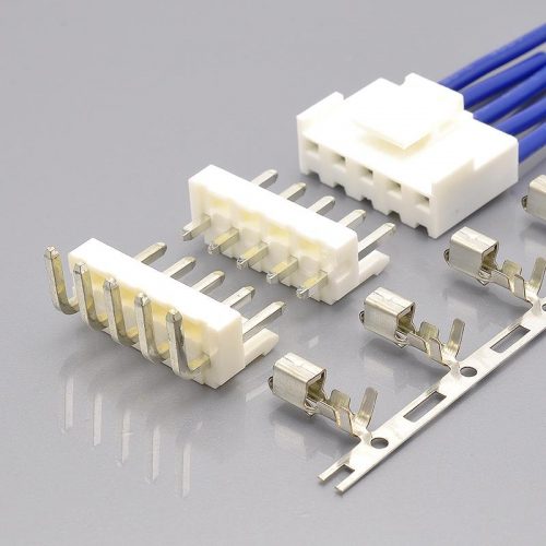
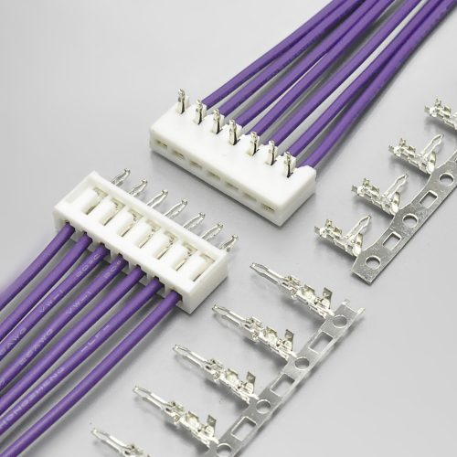
Figure 3 — KR1253 housing, the wire-side half that carries the crimped terminals
Figure 3 — KR1253 housing, the wire-side half that carries the crimped terminals
Terminal (crimp contact)
| Attribute | KONNRA documented value |
|---|---|
| Assembly type | Terminal |
| Compatible with | 50641 Series |
| Material | Phosphor bronze |
| Plating | Gold plated over Nickel (gold part number) · Tin plated (tin part number) |
| Part numbers | undefined (gold) · undefined (tin) |
| Applicable wire | AWG 28# to 32# |
| Insulation O.D. | 0.6 to 0.9mm |
| UL | E482542 |
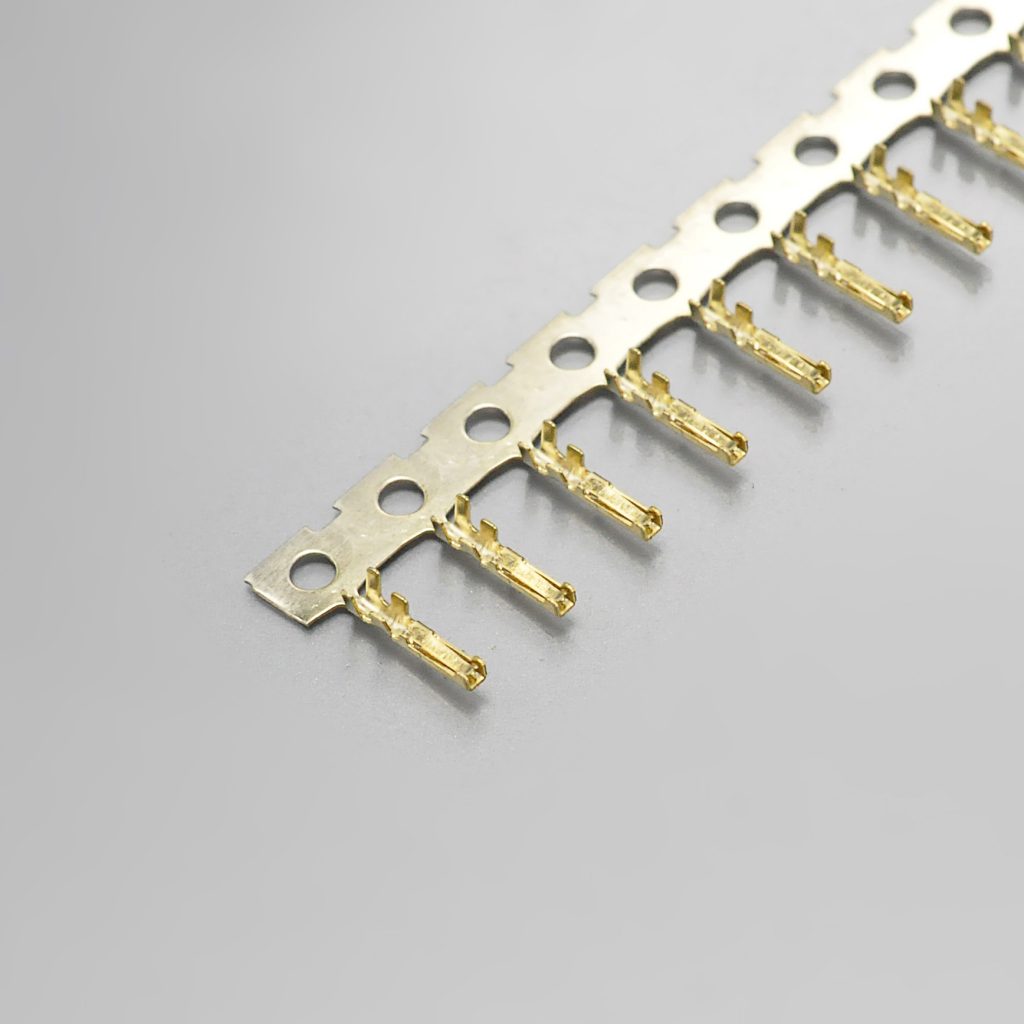
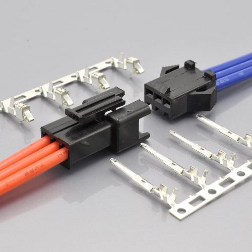
Figure 4 — KR1253 terminal, the crimp contact for AWG #28 to #32 wire
Figure 4 — KR1253 terminal, the crimp contact for AWG #28 to #32 wire
The crimp dimensions are published, which is what a harness house actually needs. PS-KR1253-01 §6.5 gives crimp height ranges of 0.53–0.60mm at AWG #28, 0.48–0.55mm at #30 and 0.43–0.50mm at #32, a crimp width of 0.85±0.1mm, an insulation crimp width of 1.00mm maximum, insulation crimp heights of 1.15 / 1.10 / 0.85mm maximum across the three gauges, crimp strength minimums of 1.36 / 0.9 / 0.7 kgf, and a strip length of 1.2–1.5mm. On the Molex side, the equivalent crimp detail lives in the separate application specifications CS-50641 and CS-50753, which PS-51146-010 points to by name rather than reproducing. If you are moving a harness between the two, the tooling and the crimp height targets are a per-terminal question on both sides.
Series documentation
- KR1253 series engineering drawing (PDF)
- KR1253 product specification (PDF)
- KR1253 package specification (PDF)
- KR1253 housing product drawing (PDF)
- KR1253 terminal product drawing (PDF)
➡️ Request drawings for your circuit count and orientation
One more configuration note. KONNRA’s product specification for the wafer lists only the right-angle SMT 90° construction, and the whole series is documented as surface mount — Molex’s own scope line for the family is “WIRE TO BOARD SMT CONNECTOR”. So neither side of this cross-reference publishes a through-hole variant of PanelMate. If your design is based on a through-hole header, it is not a PanelMate design and the KR1253 is not the part to quote against it.
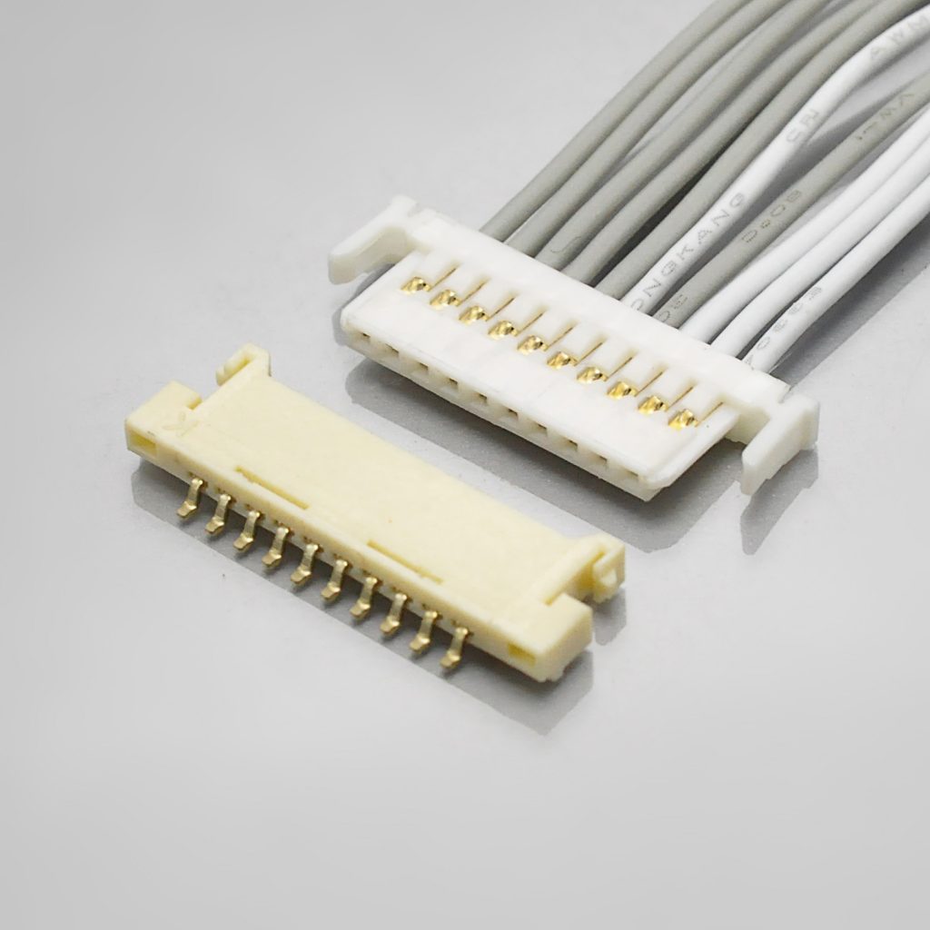
Figure 5 — KR1253 wafer and housing mated
Figure 5 — KR1253 wafer and housing mated
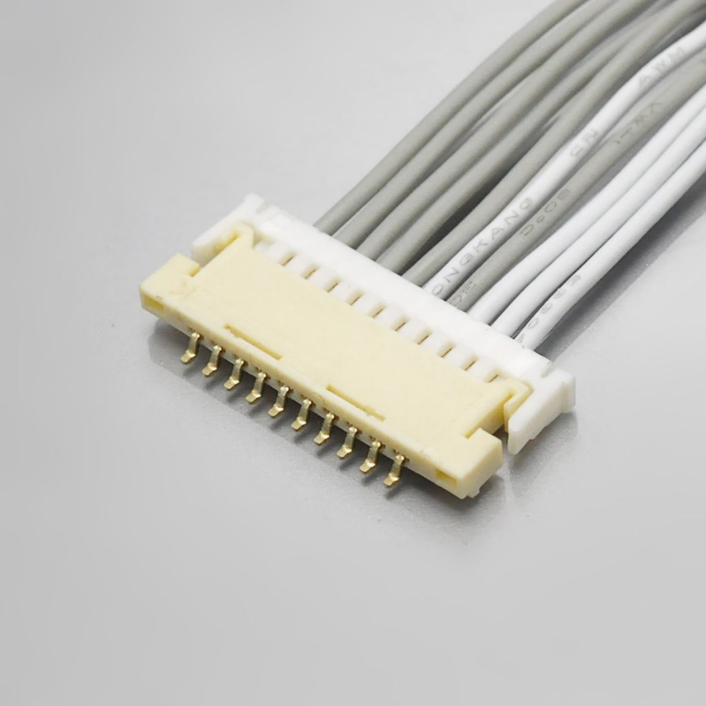
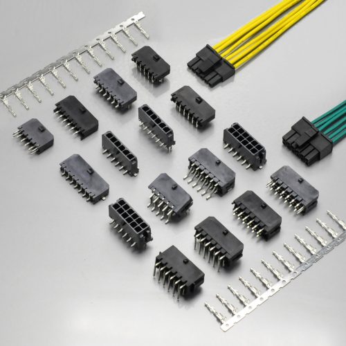
Figure 6 — KR1253 1.25mm pitch wafer and housing
Figure 6 — KR1253 1.25mm pitch wafer and housing
What the Molex PanelMate Is Used For
Molex states the series “was designed for Flat Panel Display Panels that require thin, low profile connectors” and positions it as “the lowest profile of any fully-shrouded wire-to-board system from Molex”. KONNRA describes the KR1253 as designed “for flat panel displays with extra thin connectors”, with a minimum height of 1.90mm, for flat panel LCDs such as entertainment displays, consumer electronics, personal computers and mobile devices that can be as small as 10 centimeters or less.
| Application | Why PanelMate fits |
|---|---|
| Flat panel displays and display modules | This is the design intent — an ultra-low-profile, fully shrouded, wire-to-board system for boards that have almost no vertical clearance |
| Compact consumer electronics and handhelds | 1.25mm pitch in a fully shrouded body, with a profile as low as the plug assembly you select |
| Personal computers and mobile devices | The series is documented for devices down to a very small size; the harness leaves the board as a wire bundle rather than through a panel connector |
| Boards assembled on an SMT line | SMT headers, embossed tape on reel packaging, solder tabs, and shrouded construction for handling |
| Designs that need more than 50V of headroom | 125V, against 50V for JST’s GH at the same 1.25mm pitch |
| Signal and low-power harnesses in vibration environments | Shock and vibration tested to 490 m/s² (50G) and 1.5mm P-P sweep, with friction-lock retention and shell hooks |
| Applications where the harness crosses an enclosure wall | The harness passes through the enclosure opening; the connector itself stays on the PCB |
What it is not for. At a rated 1.0A per contact this is a signal and low-power interface, not a power connector. It is not a panel-mount or bulkhead connector — Molex records Panel Mount: No. It is explicitly not for hot-mating: Molex states the product is not designed for mating or unmating under an active circuit. And with a 30-cycle durability specification on both sides, it is not a connector to design a repeated-service cycle around.
Cable Assembly Options
KONNRA builds assemblies on the KR1253 interface in the standard harness configurations:
| Cable type | Description | Typical use |
|---|---|---|
| Single-headed | Housing on one end, bare wire leads on the other | Pigtail from a display board header to a termination point |
| Same-side-head | Housing on both ends, same orientation | Extending a run between two boards |
| Reverse-side-head | Housing on both ends, reversed orientation | Routing through a fold, hinge or display pivot |
| Adapter and transition cables | KR1253 on one end, another interface on the other — for example to JST GH 1.25mm (KR1259) or SH 1.00mm | Where the two ends of a run use different connector families |
Two assembly notes that come straight from Molex’s own specification.
First, the connector must not carry the harness load. Molex’s note list requires enough wire length and slack that no continuous pulling or stress force reaches the connector when it is mated, because that damages the contact area, the crimp and the terminal lock. On a display board where the harness routes through a moving hinge, that requirement shapes the whole harness drawing.
Second, crimp tooling is a per-terminal document, not a connector document. Molex publishes the crimp details in CS-50641 and CS-50753, named in the connector product specification but not reproduced in it. KONNRA publishes its crimp dimensions inside PS-KR1253-01 §6.5, including the height windows at all three gauges. If your harness house needs to move between the two, expect to qualify the crimp again.
Key materials are prestocked, and complete connector set samples can be delivered within 45 days.
➡️ Explore KONNRA wiring harness capabilities
Sourcing the Molex PanelMate: What Procurement Teams Ask
Engineering decides that a connector will work. Procurement decides whether the supply chain around it is safe. On this family, that second question has a documented answer that does not depend on price.
“Can you be a second source without changing our design?” That is what a documented cross-reference is for. The KR1253 is specified against the Molex PanelMate system at component level — cell by cell: the housing against the 51146 series, the wafer against the 53779/53780 series, and the terminal against the 50641 series — with matching 1.25mm pitch, 125V rating, 1.0A per contact and the same AWG #28–32 wire range. We confirm equivalence against your specific part number, because circuit count, wire gauge, insulation diameter, plating finish and header height all change the answer.
“The original is going obsolete — how long can you support the programme?” This is now the strongest documented reason to open the enquiry. molex.com records the 51146 housing as Not Recommended For New Design, with a replacement part number of 5055650501, and records the 53780 header as Obsolete, under product change notification 516676 issued 2025-03-10 with an implementation date of 2026-05-31. A connector family that is being withdrawn on a published schedule is a programme risk regardless of who supplies the replacement. Ask your second source for a product lifecycle statement and a change notification process, not just a price.
“How long for samples?” Complete connector set samples can be delivered within 45 days. Where you need to validate crimp pull-out force or retention before committing — both of which are specified in detail on this series by both manufacturers — sample harnesses can be supplied from the same process used in production.
“What qualifications do you hold?” ISO9001, ISO14001, IATF16949, ISO45001:2018, ISO13485, IPC620, and UL product and operational safety certifications. The KR1253 wafer, housing and terminal pages each carry a UL file reference, E482542, at component level — which is the level your qualification documentation wants it, rather than a brand-level claim.
“How do we know the parts match your documentation?” A CNAS-accredited laboratory with 45+ sets of precision testing instruments, with dimensional and electrical verification data available on request. 95% of production processes carry full-line intelligent visual CCD inspection; automotive series receive 100% CCD inspection. On this specific series, note that the published documents themselves carry two internal conflicts — the 30mΩ contact resistance on the product page against 20mΩ everywhere else, and the 250V against 500V withstanding voltage. Ask which document governs, and ask for the test report.
“Are you a manufacturer or a trader?” A manufacturer. Dongguan Konnra Electronics Co., Ltd., founded 2004, with in-house mould design, injection moulding, stamping, assembly, and inspection — so the connector and the cable assembly come from one quality system.
“What volumes can you support?” KONNRA reported 2025 sales of RMB 310 million, with connectors at 60% and wiring harnesses at 40% of the product mix, across four production bases with automation coverage exceeding 95%.
“Who else buys from you?” KONNRA states that it serves global cooperative clients including BYD, Volkswagen, and DJI.
➡️ Request the vendor qualification pack — certificates, test capability summary, product drawings, and a sample plan in one enquiry.
How to Get a Cross-Reference Check on Your MX1.25 Part Number
Most PanelMate enquiries stall on the same thing: the buyer is not sure what information the supplier needs, so the enquiry never gets sent. Here is the complete list.
Send us:
- The original part number, if you have it — a housing such as
51146-**00, a terminal such as50641-8***or50753-8***, or a plug assembly such as53780-**19 - Circuit count — the Molex
53780part list runs to 20, and KONNRA documents 2–30; 30 needs to be raised explicitly - Header height required — Molex offers 1.03mm (55063), 1.3mm (53779) and 1.85mm (53780); KONNRA documents a 1.90mm minimum height for KR1253, so the height is the first thing to reconcile
- Wire gauge, and the insulation outside diameter. Molex allows φ0.9mm at #28 and #30 but only φ0.55mm at #32; KONNRA documents 0.6–0.9mm, so AWG #32 needs specific confirmation
- Plating finish required — gold flash or a specified thickness. Molex publishes 0.200µm / 0.203µm minimum on the mating interface; KONNRA documents the finish but not the thickness
- Terminal series, if your approved part number names one — 50641 for AWG #28–30 or 50753 for AWG #30–32. KONNRA documents a single terminal pair across AWG #28–32
- Your required operating temperature. Molex rates the family to +85°C; KONNRA documents +105°C. This is the largest single documented difference
- Your load current and circuit count, so the per-circuit rating and the sum-of-current note can be settled rather than assumed
- Whether the application requires the connector to fix to an enclosure panel. If it does, neither part number is the right one — Molex records Panel Mount: No
- Application and annual volume, plus a drawing or photo if the part number is unreadable or the design has been reverse-engineered
When you send a part number, we will confirm four things against Molex’s own documentation: the terminal that matches your wire gauge and insulation diameter, the gold thickness you need, the header height and mounting type, and whether your design needs an option beyond the published range so it can be quoted honestly rather than assumed. Those four are where a PanelMate cross-reference most often goes wrong.
What you get back: a mapped KONNRA part number with the relevant product and engineering drawings, a specification comparison against your original part, and a sample and quote plan.
Engineer’s Pre-Release Checklist
Run this before you release a drawing for a PanelMate-family connector.
- Series number confirmed, not inferred. At 1.25mm, Molex PanelMate (51146) and Molex PicoBlade (51021) are different systems with different footprints. They do not mate.
- Pitch measured, not assumed. 1.25mm also covers Hirose DF13/DF14 and JST GH; 1.20mm is Molex Pico-EZmate. None of them mate.
- Panel-mount requirement settled. Molex records Panel Mount: No for this family. If the connector has to fasten to the enclosure, stop and re-specify the family.
- Header height matched to the original — 1.03mm, 1.3mm or 1.85mm by plug assembly, against a KONNRA-documented 1.90mm minimum height.
- Circuit count inside both published ranges — Molex
53780part list to 20; KONNRA 2–30. Counts above 20 need explicit confirmation. - Wire gauge and insulation diameter inside both windows — Molex φ0.9mm max at #28/#30 and φ0.55mm max at #32; KONNRA 0.6–0.9mm. At AWG #32 the two windows do not fully overlap.
- Operating temperature aligned to the original — +85°C per Molex, +105°C per KONNRA. If the design assumes 105°C, substantiate it.
- Dielectric withstanding voltage resolved — 250V AC (RMS), 1 minute per Molex and per KONNRA’s product page and housing drawing; 500V AC, 1 minute per KONNRA’s specification PDF and terminal drawing. Quote one, and know which.
- Contact resistance taken from the right document — 20mΩ max on both sides; the 30mΩ Max on KONNRA’s product-page table is that page’s own outlier.
- Plating thickness specified — Molex publishes 0.200µm / 0.203µm minimum on the mating interface; KONNRA publishes “gold flash” with no thickness.
- Sum of current across circuits checked against the maximum allowable, not just the per-circuit figure.
- Crimp specification qualified — Molex crimp details live in CS-50641 / CS-50753; KONNRA publishes height and width windows in PS-KR1253-01 §6.5, and its published 15-position withdrawal-force row should be treated as unverified.
- Service procedure checked for hot-mating. Both sides exclude it; Molex states unmating under an active circuit may cause a spark and product defect.
- Terminal extraction procedure written. Molex advises fitting a new housing after extracting a terminal, because the lance deforms and retention drops enormously.
- Mating axis alignment part of the build instruction — straight along the axis, or under 10° if diagonal mating is unavoidable.
- Withdrawal instruction written — hold wires together, release the lock completely, withdraw slowly and axially, never at an angle.
- Wire construction confirmed as tin-plated copper stranded, or raised for evaluation if it is not.
- All solder tails and fitting nails soldered, per Molex’s requirement. On a board whose only retention is the solder interface, this is a reliability requirement rather than a process preference.
- Harness strain relief designed so no continuous load reaches the mated connector, and the harness not used to carry the board.
- Reflow profile agreed against both documents — peak 250 +5/−0°C (Molex) versus 255±5°C (KONNRA), with the same preheat and time-above-liquidus windows. Air reflow assumed; N₂ reflow requires separate evaluation.
➡️ Send us your drawing. We will review it against the KR1253 specification and come back with any mismatch we find — before you commit tooling. Submit a drawing for review
Why Source PanelMate-Family Connectors from KONNRA
Dongguan Konnra Electronics Co., Ltd. (brand: KONNRA) was founded in 2004 and is a National High-Tech Enterprise specialising in connector and wiring harness research, development, production, and sales.
Manufacturing depth. A vertically integrated process covering precision mould design and manufacturing, automation design, precision injection moulding, stamping, assembly, and CCD visual inspection. Automation coverage exceeds 95% across production lines.
Testing and validation. A CNAS-accredited laboratory with 45+ sets of precision testing instruments, and CAE analysis — contact nonlinear analysis, material nonlinear analysis, motion simulation, thermal field analysis, and high-frequency analysis — performed in Ansys 2022 R1. Verification data is available on request.
Inspection coverage. Full-line intelligent visual CCD inspection covers 95% of production processes, using Mitsubishi and Panasonic PLC control systems with FA25–35mm optical lenses and 5-megapixel cameras. Automotive connector series receive 100% CCD visual inspection.
Quality systems. ISO9001, ISO14001, IATF16949, ISO45001:2018, ISO13485, IPC620, and UL product and operational safety certifications, with automotive-grade series additionally certified to LV214 and US CAR-2.
Capacity and delivery. Production bases in Dongguan Wangniudun (30,000 m², 350+ employees), Dongguan Changan (10,000 m², 150+ employees), and Hunan Daoxian (2,600 m², 100+ employees), with regional offices in Beijing, Chongqing, Hunan, Shanghai, and Kunshan. Key materials are prestocked, and complete connector set samples can be delivered within 45 days. KONNRA reported 2025 sales of RMB 310 million, with connectors at 60% and wiring harnesses at 40% of the product mix, and has served global cooperative clients including BYD, Volkswagen, and DJI.
Custom and joint R&D. Where a standard part does not fit — a header height that is not in the published range, a defined gold thickness, a non-standard harness length, or a transition to another interface — KONNRA supports customer joint R&D customisation.
How to Identify Whether Your Connector Is a PanelMate
If you are holding a connector and a drawing you cannot match, work through these in order:
- Measure the pitch. 1.25mm points at Molex PanelMate, Molex PicoBlade, Hirose DF13/DF14 or JST GH. 1.20mm points at Molex Pico-EZmate. 1.00mm points at Pico-Clasp or JST SH.
- Measure the mated height. PanelMate is sold by height — 1.03mm, 1.3mm or 1.85mm by plug assembly. If the mated stack is very low and the board side is SMT, PanelMate is the likely family.
- Check the mounting type. PanelMate’s board side is surface mount; Molex’s scope line for the family is “Wire to Board SMT Connector”. A through-hole header at 1.25mm points elsewhere.
- Count the positions and check the packaging. The Molex
53780part list runs to 20 circuits, and the headers ship embossed tape on reel — consistent with an SMT line. - Look for the solder tabs. PanelMate’s header relies on solder tabs / fitting nails and a fillet tail design for PCB retention; their presence is consistent with the family.
- Read the part number if there is one. 51146 is the housing, 53779 / 53780 / 55063 are plug assemblies, and 50641 / 50753 are crimp terminals.
- Check whether the housing is meant to fix to a panel. PanelMate housings are not panel-mount parts. If a part is fastened through a chassis, it is a different family.
If you are still unsure, photograph the connector next to a ruler, with any part number markings visible, and send it to us. At this pitch, the measurement identifies the family; the part number identifies the variant — and on this family the height is as important as the pitch.
Frequently Asked Questions
What is a Molex PanelMate connector?
Molex PanelMate is a 1.25mm-pitch, single-row, wire-to-board connector system designed as an ultra-low-profile solution for flat panel displays. Molex builds it from a 51146 receptacle housing, 50641 or 50753 crimp terminals, and 53779, 53780 or 55063 SMT plug assemblies. It is rated 125V AC (RMS)/DC and 1.0A maximum per contact, for AWG #28, #30 and #32, over −40°C to +85°C.
Is Molex MX1.25 the same as PanelMate?
No — “MX1.25” is trade shorthand for the 1.25mm pitch, and Molex sells more than one family at that pitch. At 1.25mm, MX1.25 can mean PanelMate (51146) or PicoBlade (51021 / 53048). They share the pitch, the 125V rating and the 1.0A per-contact figure, and they do not mate with each other. Confirm which family your drawing names before cross-referencing.
What is the difference between PanelMate and PicoBlade?
Configuration and profile. PanelMate is wire-to-board only, and exists to deliver the lowest profile fully-shrouded wire-to-board system in Molex’s range — sold at 1.03mm, 1.3mm and 1.85mm by plug assembly. PicoBlade covers wire-to-board and wire-to-wire, uses a two-point contact design, and is available in 2 to 15 circuits. Both are 1.25mm, both are 125V, both are 1.0A per contact. The choice is driven by profile height and configuration, not by the electrical rating.
Is PanelMate a panel-mount connector?
No. Despite the name, Molex’s own part data for the 51146 housing records Panel Mount: No. The name refers to flat panel displays: Molex states the series “was designed for Flat Panel Display Panels that require thin, low profile connectors”. The connector mounts to the PCB; the wire harness passes through the enclosure as a bundle. If your design needs a connector fastened through a chassis panel, this is not the family.
What is the current rating of the PanelMate?
1.0A maximum per contact, per molex.com part data for the 53780 header. Molex also notes that the sum of the current used on several circuits must not exceed the maximum allowable current, so the per-circuit figure is not the whole answer. KONNRA documents 1A, rated at 28 AWG.
What is the voltage rating of the PanelMate?
125V AC (RMS)/DC, stated in Molex’s product specification PS-51146-010 as the maximum allowable voltage, and repeated as 125V in molex.com part data. KONNRA documents the same 125V AC/DC — on the voltage rating, the two sides agree.
What wire does the PanelMate use?
AWG #28, #30 and #32, with a gauge-specific insulation window: φ0.9mm maximum for #28 and #30, and φ0.55mm maximum for #32. Molex also states that the applicable wire is, in principle, tin-plated copper stranded wire, and that other constructions require consultation and evaluation. Note that KONNRA documents a single window of 0.6 to 0.9mm, which does not extend down to Molex’s φ0.55mm figure for AWG #32.
Which PanelMate crimp terminal do I need?
There are two: 50641-8*** for AWG #28–30 and 50753-8*** for AWG #30–32. The ranges overlap at AWG #30, so the gauge alone does not select the terminal. Molex’s part data for 506418041 also gives 0.203µm minimum plating on both the mating and termination interfaces, and a wire insulation diameter of 0.50–0.90mm. KONNRA documents one terminal pair — T12530PG0201A (gold) and T12530PT0101A (tin) — across AWG #28–32.
How many circuits does the PanelMate come in?
Molex’s 53780 part list enumerates 2, 3, 4, 5, 6, 7, 8, 9, 10, 14, 15 and 20 circuits. KONNRA documents the KR1253 as 2–15, 20 and 30 on the housing drawing and 2–30 on the product page, while the wafer drawing states 2~20,30. 30 positions is beyond the published Molex header range — confirm the count explicitly if you need it.
What is the dielectric strength of the PanelMate?
Molex specifies 250V AC (RMS) for one minute between adjacent terminals or ground, with a pass criterion of no breakdown — PS-51146-010 §4-1-3. KONNRA’s product-page table and housing drawing also state 250V AC/minute, so the product page agrees with the original. However, KONNRA’s specification PDF §5.3 and the terminal drawing state 500V AC for one minute. Resolve which KONNRA document governs before quoting a figure. The rated voltage — 125V — is 125V on both sides either way.
What is the operating temperature range of the PanelMate?
−40°C to +85°C, and Molex states this includes the terminal temperature rise generated by conducting electricity, that applicable wires must also meet the range, and that the connector must not freeze at low temperature. KONNRA documents −40°C to +105°C for the KR1253. This is the largest single documented difference between the two specifications.
What is the durability of the PanelMate?
30 mating cycles, per PS-51146-010 §4-3-1, after which contact resistance must remain within 40mΩ — and molex.com part data for the 53780 header states Durability (mating cycles max): 50. KONNRA specifies 30 cycles for the KR1253, so 30 is the figure both sides substantiate.
Is the PanelMate going obsolete?
Molex’s own part data says so. The 51146 housing is recorded as Not Recommended For New Design, with 5055650501 as a replacement part number, and the 53780 header is recorded as Obsolete under product change notification 516676, issued 2025-03-10 with an implementation date of 2026-05-31. If your programme is still buying this family, that schedule belongs in your risk register.
Can the PanelMate be mated under load?
No. Molex states the product “is not designed for the mating and unmating of the connectors to be performed under the condition of an active electrical circuit”, and that doing so “may cause a spark and product defect”. If your service procedure disconnects this connector live, the procedure needs changing.
What is the KONNRA equivalent of the PanelMate?
KR1253 — documented at 1.25mm pitch, 2–30 positions, 1A, 125V, single row, wire-to-board, and offered as three separately orderable components: a right-angle SMT wafer (declared compatible with the 53779/53780 series), a housing (51146 series) and a terminal (50641 series). KONNRA’s specification also publishes crimp dimensions, retention forces and environmental test conditions that make a like-for-like comparison possible — including the points where the two sides differ.
How long does it take to get samples?
Complete connector set samples can be delivered within 45 days. Key materials are prestocked. If you need to validate crimp pull-out force, retention or the operating temperature question before committing, ask for sample harnesses from the production process rather than bench-built ones.
Start Your Cross-Reference Check
KONNRA supplies the KR1253 series as individual components or as complete pre-crimped cable assemblies, and builds adapter and transition harnesses to order.
- Request a quote — KR1253 pricing, MOQ and configuration options for your circuit count, height and plating
- Request a sample — complete connector set samples within 45 days
- Request cross-reference verification — confirm KR1253-to-PanelMate equivalence against your specific part number, including the terminal for your wire gauge and insulation diameter
- Request a height match — Molex sells this family at 1.03mm, 1.3mm and 1.85mm; KONNRA documents 1.90mm minimum height, so the height is the first thing we will reconcile
- Request AWG #32 confirmation — Molex allows φ0.55mm insulation at #32, while KONNRA documents 0.6–0.9mm
- Request the temperature position — Molex rates the family to +85°C, KONNRA documents +105°C
- Request drawings — series engineering drawing, product specification, package specification and component drawings
- Request a vendor qualification pack — certificates, test capability summary and quality documentation
- Request adapter harnesses — KR1253 to JST GH 1.25mm, to SH 1.00mm, or another interface on the far end
- Submit a drawing for review — we will flag any specification mismatch before you commit tooling
Contact KONNRA Electronics
- Phone: (86)-769-85449875
- Email: [email protected]
- Address: No.6 Nanchang South Road, Chijiao, Wangniudun, Dongguan, Guangdong, China
- Contact us
➡️ Explore the full 1.25mm pitch range · Molex connector alternatives · Wire-to-board connector catalogue
Sources and method. Every figure in this guide is taken from a published manufacturer document, and the source is named so it can be re-checked.
Molex PanelMate figures come from Molex’s own documentation. From the Molex product specification PS-51146-010 (revision E, “1.25mm Pitch Wire to Board SMT Connector”, document file PS-51146-010, sheets 1–17): the scope statement; the part-number table listing receptacle terminals 50641-8*** (AWG #28–30) and 50753-8*** (AWG #30–32), receptacle housing 51146-**00, and plug assemblies 53779-**19 / 53779-**70 (H=1.3), 53780-**19 / 53780-**70 / 53780-**20 / 53780-**29 (H=1.85) and 55063-**19 / 55063-**70 (H=1.03); the maximum allowable voltage of 125V AC (rms)/DC; the allowable current and applicable wire table giving 1A at AWG #28 with φ0.9mm max insulation, 1A at AWG #30 with φ0.9mm max insulation, and 1A at AWG #32 with φ0.55mm max insulation; the ambient temperature range of −40°C to +85°C including terminal temperature rise, with the notes on non-operating connectors after reflow, wire temperature compliance and freezing at low temperature; the 20mΩ max contact resistance measured by dry circuit at 20mV max and 10mA; the 5mΩ max contact resistance on the crimped portion; the 100MΩ min insulation resistance at 500V DC; the 250V AC (rms) for 1 minute dielectric strength test with a no-breakdown criterion; the insertion force of 2.1N (0.22 kgf) per circuit maximum and withdrawal force of 0.2N (0.02 kgf) per circuit minimum at a rate of 25±3mm/minute; crimp pull-out forces of 9.8N (1.0 kgf) at #28, 4.9N (0.5 kgf) at #30 and 2.9N (0.3 kgf) at #32; the crimp terminal insertion force of 4.9N (0.5 kgf) maximum, crimp terminal retention force of 4.9N (0.5 kgf) minimum and header terminal retention force of 2.0N (0.2 kgf) minimum; 30 cycles repeated insertion/withdrawal with a 40mΩ max criterion; the 30°C max temperature rise; the vibration condition of 1.5mm P-P, 10–55–10 Hz in 1 minute, 2 hours in each of X, Y, Z axes with the cable fixed and its 40mΩ max and 1 microsecond max discontinuity criteria; the mechanical shock condition of 490 m/s² (50G), half-sine, 11ms, 3 shocks in 6 directions (18 total); the heat resistance test at 85±2°C for 96 hours, cold resistance at −40±3°C for 96 hours, humidity at 60±2°C / 90–95% RH for 96 hours with 10MΩ min insulation resistance afterwards, temperature cycling of 5 cycles of −55°C for 30 minutes and +105°C for 30 minutes, salt spray of 48±4 hours at 35±2°C with 5±1% NaCl, SO₂ gas at 50±5ppm for 24 hours at 40±2°C and NH₃ gas from a 28% solution for 40 minutes at 25mL per 1L, solderability at 245±5°C for 3±0.5 seconds with 95% coverage, and resistance to soldering heat including hand soldering at 370–400°C for a maximum of 5 seconds; the reflow profile of 250 +5/−0°C maximum peak, 20–40 seconds at 230°C minimum, 90–120 seconds of preheat at 150–200°C and a maximum reflow count of 1; and the full note list, including the exclusions on hot-mating, washing, sympathetic vibration, carrying the substrate with connectors mated, load in the pitch, span and rotational directions, the sum-of-current restriction, tin-plated copper stranded wire as the applicable construction, replacement of the housing after extracting a crimp terminal, the withdrawal instruction, mating alignment under 10°, the requirement to solder all terminal tails and fitting nails, the 0.02mm maximum PCB warpage for coplanarity, the pre-mount-only coplanarity guarantee, the reference to crimp specifications CS-50641 and CS-50753, the air-reflow assumption with nitrogen reflow requiring separate evaluation, and the requirement to consult before using a flexible or other special PCB.
Also from Molex: the molex.com part-detail page for 537800870 (“1.25mm Pitch PanelMate Header, Surface Mount, Right-Angle, 1.90mm Height, 8 Circuits”), giving Current – Maximum per Contact 1.0A, Voltage – Maximum 125V, Durability (mating cycles max) 50, Temperature Range – Operating −40° to +85°C, material and plating data (phosphor bronze metal, gold plating on the mating interface, tin on the termination), single row, right angle, shrouded, PCB retention, 94V-0, agency values UL E29179 and CSA LR19980, and the lifecycle status Obsolete with PCN 516676 dated 2025-03-10 and an implementation date of 2026-05-31; the molex.com part-list page for series 53780, giving the circuit-count facets 2, 3, 4, 5, 6, 7, 8, 9, 10, 14, 15 and 20, Plating min – Mating 0.200µm, Plating min – Termination 3.000µm and Embossed Tape on Reel packaging; the molex.com part-detail page for 511460500, giving Panel Mount: No, the status Not Recommended For New Design with replacement part 5055650501, −40° to +85°C, 94V-0, UL E29179 and CSA LR19980; and the molex.com part-detail page for 506418041 (“PanelMate Crimp Receptacle Terminal, 30-28 AWG, Reel Gold (Au)”), giving Wire Size (AWG) 28, 30, Wire Insulation Diameter 0.50–0.90mm, Plating min – Mating 0.203µm, Plating min – Termination 0.203µm, phosphor bronze, and the status Not Recommended For New Design with replacement part 5054311100. Molex’s series-level description of PanelMate as “the lowest profile of any fully-shrouded wire-to-board system from Molex”, designed for “Flat Panel Display Panels that require thin, low profile connectors”, with an SMT header featuring robust solder tabs and a solder-conducting SMT fillet tail design, is taken from Molex product information as republished in the distributor datasheet for part 51146-0500 (RS Online document, generated 2016-class Molex datasheet content). The Molex part numbers for the plug assemblies and terminals, and the restricted names “H=1.03 / H=1.3 / H=1.85”, are as printed in the PS-51146-010 part-number table.
KONNRA KR1253 figures come from KONNRA’s published documentation. From the KR1253 product page, “KR1253 Equivalent To Molex PanelMate mx1.25 alternatives connector”: the pitch of 1.25mm, 2–30pin circuits, 1A current, 125V voltage, single row, wire-to-board category, and its cross-reference to Molex PanelMate; the general specification table listing PA66/PA6T/UL94/Phosphor Bronze/Brass, Insulation O.D 0.6 to 0.9mm, Withstanding Voltage 250V AC/minute, −40°C to +105°C, Contact Resistance 30mΩ Max, Insulation Resistance 100MΩ Min and Product Plating Tin or Gold flash over Nickel; and the overview and advantages text covering the flat-panel-display design intent, the 1.90mm minimum height, the KONNRA-designed crimp latch, the construction that prevents backwards insertion, SMT headers and solder tails for PCB retention, friction locks and shell hooks, the blade-type pin design, the anti-flux-penetration shielding, phosphor bronze contacts and the AWG #26–#32 / 1.0A statement in the overview text. From the KR1253 product specification PS-KR1253-01 (issued and revised 2022/2/26, edition A1): the part numbers H125301****01A, T12530PG0201A, T12530PT0101A and C1253RS1**09*****RA; the material and surface-treatment table (housing PA66 UL94 V-0; terminal phosphor bronze with Tin/Gold plated over nickel; right-angle SMT 90° wafer with PA9T base, phosphor bronze contact and brass solder tab, all gold plated over nickel; the straight SMT 180° rows marked N/A); the ratings table (125V AC/DC, 1A at 28AWG, −40°C to +105°C, AWG 28# to 32# with insulation O.D. 0.6 to 0.9mm); §5.1 contact resistance 20 milliohms max by dry circuit at 20mV max and 100mA max per EIA-364-23C; §5.2 insulation resistance 100 Megohms min at 500V DC for 1 minute per EIA-364-21B; §5.3 dielectric strength at 500V AC for 1 minute with a no-breakdown criterion per EIA-364-20A; §6.1 insertion and withdrawal force at 25.4±3mm/minute per EIA-364-13D referencing §8.0; §6.2 terminal insertion force 0.5 kgf (4.9N) max; §6.3 terminal/housing retention force 0.7 kgf (6.86N) min; §6.4 pin retention force 0.3 kgf (2.94N) min; §6.5 crimp heights of 0.53–0.60 / 0.48–0.55 / 0.43–0.50mm for 28/30/32 AWG, crimp width 0.85±0.1, insulation crimp width 1.00 max, insulation crimp heights 1.15 / 1.10 / 0.85 max, crimp strength 1.36 / 0.9 / 0.7 kgf min and stripping 1.2–1.5mm; §7.1 durability of 30 cycles at up to 10 cycles per minute with a 40 milliohms max criterion per EIA-364-09C; §7.2 temperature rise 30°C max per EIA-364-70B; §7.3 vibration at 1.5mm P-P, 10–55–10 Hz in 1 minute, 2 hours in each axis with 40mΩ max and 1 microsecond max discontinuity per EIA-364-28B; §7.4 shock at 490 m/s² (50g) with 3 strokes in each of X, Y, Z per EIA-364-27B; §7.5 heat resistance 105±2°C for 96 hours; §7.6 cold resistance −40±2°C for 96 hours; §7.7 humidity at 40±2°C, 90–95% RH for 96 hours with 100 Megohms min and dielectric strength to meet §5.3; §7.8 thermal shock of 5 cycles between −40°C and +105°C; §7.9 salt spray of 24 hours at 35±2°C with 5±1% solution; §7.10 solderability at 245±5°C for 3±0.5 seconds with 95% coverage; §7.11 solder resistance at 255±5°C for 5–10 seconds; §8.0 the insertion and withdrawal force table by circuit count (including the 2-circuit 0.44 insertion / 0.04 withdrawal values and the 30-circuit 6.60 / 0.60 values, and the 15-circuit row showing 3.30 / 2.30 / 2.30); and §9.0 the SMT infrared reflow condition of 5–10 seconds at a 255±5°C peak, 20–40 seconds at minimum 230°C and 90–120 seconds of preheat at 150–200°C. From the KR1253 series engineering drawing (KR1253-Series-Drawing_2026.5.13.pdf): the housing sheet statement of Withstanding voltage 250V AC/minute, the Nylon 66 UL 94V-0 insulator, the circuit counts 2~15, 20, 30 and the housing ordering code with its white, black and beige colour options; the terminal sheet statement of Withstanding voltage 500V AC/minute, 20mΩ Max contact resistance, phosphor bronze material, AWG#28~#32 conductor size, 0.6~0.9mm insulation O.D. and the two plating part numbers; and the wafer sheet for the “MX1.25 Ultra-thin SMT 90° WF” with high temperature thermoplastics insulator, phosphor bronze contact, brass solder nail, gold plating over nickel, circuit counts stated as 2~20,30 and part number C1253RS********A. From the KONNRA component pages for the right angle wafer, the housing and the terminal: the declared compatibility with the 53779/53780, 51146 and 50641 Molex series respectively, the wafer physical data (PA66, beige, phosphor bronze, gold flash over nickel, AWG 28#–32#) and the UL E482542 reference carried on all three pages. KONNRA’s 1.25mm pitch category page is the source for the KR1253 series listing and for the other 1.25mm family entries used in the comparison table. The company facts in the “Why Source PanelMate-Family Connectors from KONNRA” section are KONNRA’s own published company information.
Values not stated in the documents reviewed for this guide are marked “Not documented” or flagged for confirmation rather than estimated. Specifically: KONNRA does not publish a plating thickness, an applicable wire construction, SO₂ or NH₃ gas test results, or a per-gauge terminal split for the KR1253; KONNRA’s product page states a 30mΩ Max contact resistance that conflicts with the 20mΩ Max figure in its own specification and drawings, and states a 250V AC/minute withstanding voltage where its specification PDF and terminal drawing state 500V AC/minute; KONNRA’s published 15-position withdrawal-force row reads as a typographical error; and the KONNRA wafer drawing’s circuit range (“2~20,30”) is inconsistent with the housing drawing (“2~15,20,30”). Each of these is identified in the body of the guide and should be confirmed with the manufacturer before it is quoted in a qualification document.