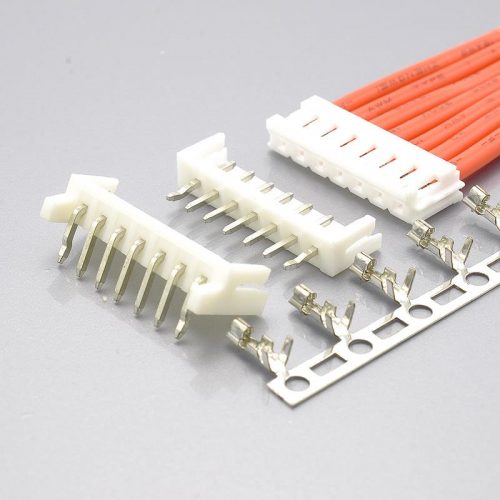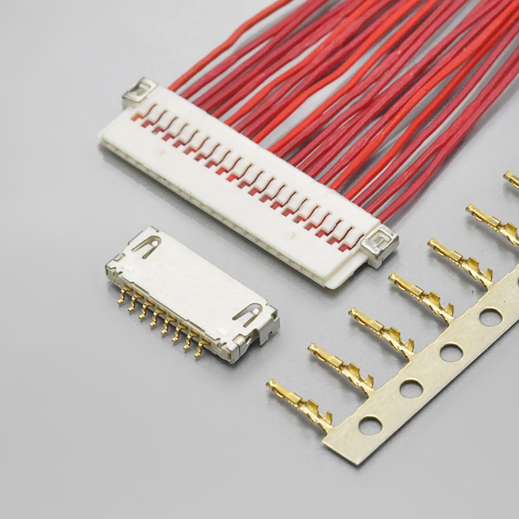
Quick answer: The Hirose DF19 is a 1.0mm pitch, single-row, low-profile wire-to-board connector supplied in 8, 14, 20 and 30 contacts. Its defining feature is that one receptacle accepts three different plug types — crimped discrete wire, FPC, or micro-coaxial cable. It is rated 100V AC, with a current rating that depends on your wire: 1A at AWG #28, 0.9A at #30, 0.8A at #32, 0.5A at #36, 0.5A for FPC, and 0.3A for AWG #40 micro-coaxial cable. Operating temperature is −35°C to +85°C, contact resistance is 30mΩ max (50mΩ max on the FPC path), and rated durability is 30 insertion/withdrawal cycles. Hirose describes it as the de facto standard for LCD panel connections on panels under 12 inches. The KONNRA KR1002 series is documented as its cross-reference equivalent, covering 8 to 30 circuits at 1.0mm pitch in a right-angle SMT wafer, with housing and crimp terminal.
At a glance
| Manufacturer of the original | Hirose Electric Co., Ltd. — not JST |
| Series | DF19 |
| Pitch | 1.0mm |
| Configuration | Single row, board-to-cable / board-to-FPC / board-to-micro-coaxial cable |
| Positions | 8, 14, 20, 30 only |
| Mated interface | One receptacle accepts discrete-wire, FPC or micro-coax plugs |
| Voltage rating | 100V AC |
| Current rating | 1A / 0.9A / 0.8A / 0.5A by wire gauge (see the table below) |
| Operating temperature | −35°C to +85°C |
| Durability | 30 cycles |
| Receptacle heights | 1.65mm, 1.1mm or 1.0mm depending on mounting style |
| Typical use | LVDS display connections in panels under 12 inches |
| KONNRA equivalent | KR1002 (8–30 circuits, 1.0mm pitch) |
Because the DF19 is the connector that links a display panel’s LVDS harness to a mainboard, the questions engineers and buyers actually ask about it are narrow and practical: how many positions, which wire, which mounting height, and whether a second source exists. This guide answers those with every figure traced to Hirose’s or KONNRA’s own documentation — and it flags the four places where the two documents disagree, instead of averaging them.
What this guide covers:
- Is the DF19 a JST or a Hirose connector? (It is Hirose — this is the most common mix-up about the series)
- Hirose DF19 and KONNRA KR1002 specifications, side by side
- Complete part number cross-reference — receptacles, plugs, contacts, ground plates
- Why the current rating changes with your wire gauge, and why a single “1A” hides that
- The 3-in-1 interface: one receptacle, three cable systems
- Mounting styles and what each one costs you in board height
- Crimp contacts, applicable wire, strip length, and the tooling requirement
- DF19 vs the other Hirose 1.0mm and 1.25mm series
- Sourcing questions procurement teams ask
- A cross-reference checklist for your specific part number
Is the DF19 a JST or a Hirose connector?
The DF19 is a Hirose Electric series. There is no JST series designated DF19.
The mix-up is common enough to be worth stating plainly, and there are two reasons for it.
First, the two brands’ small wire-to-board connectors are used side by side on the same boards, and both get called “JST connectors” in conversation — JST stands for Japan Solderless Terminal, and over time the name has become a generic label for any small crimp-style wire-to-board connector. A DF19 receptacle sitting next to a JST SH header on a laptop mainboard is easy to mislabel.
Second, the two families share a pitch. Hirose’s DF19 and JST’s SH are both 1.0mm pitch — and KONNRA’s cross-reference range reflects that symmetry, with KR1002 for the Hirose DF19 and KR1000 for the JST SH. Same pitch, same board, same supplier conversation, completely different mating interface.
They are not intermateable. A 1.0mm pitch Hirose DF19 receptacle will not accept a JST SH plug, and vice versa. If one end of your design is a DF19 receptacle and the other end of your harness is an SH housing, you need a transition harness rather than a direct mate. KONNRA’s harness division builds adapter and transition cables to order, which is the usual route for exactly this situation.
Rule of thumb: at 1.0mm pitch, always cross-reference on the part number, never on the pitch or the appearance. DF13, DF14, DF19, DF20, DF50, FX15, JST SH and JST GH all live within a fraction of a millimetre of each other, and none of them mate with any other.
What Is the Hirose DF19 Connector?
The DF19 is a 1.0mm pitch, single-row, low-profile wire-to-board connector for high-speed differential signalling. Hirose states it is accepted by the industry and market as the “de facto” standard for LCD panel connections, specifically panels under 12 inches, and describes it as a high-performance connector for LVDS high-speed differential signals.
The unusual part is the interface. Hirose designed the DF19 so that a single receptacle will accept plugs terminated three different ways, and so that the finished plug assembly has the same external dimensions whichever way you terminate it. That is what makes the series a design decision rather than just a part number: a board can ship with a crimped harness in one build and an FPC tail in another, using the same receptacle footprint.
Key characteristics:
- 1.0mm pitch, single row — 8, 14, 20 or 30 contacts
- One receptacle, three cable systems — crimped discrete wire, FPC, or micro-coaxial cable
- Uniform plug dimensions — the plug assembly’s external dimensions stay the same across all three termination types
- Low profile — receptacles at 1.65mm, 1.1mm or 1.0mm depending on mounting style
- Ground connection through metal grounding plates — the ground line connects to a metal shell, which is what makes the series suitable for shielded LVDS runs
- High-speed signal integrity — specified for LVDS differential pairs
- Four mounting styles — top-board, offset, reverse-mount offset and vertical
- Glow wire compliant — compliant with IEC60695-2-11
- Gold-plated contacts as standard on the receptacle and the crimp contact
- Thin cable accommodation — accepts micro-coaxial cable up to Ø1.6mm and FPC up to 1.7mm
- 30-cycle rated durability — a low figure, and one that surprises designers (see below)
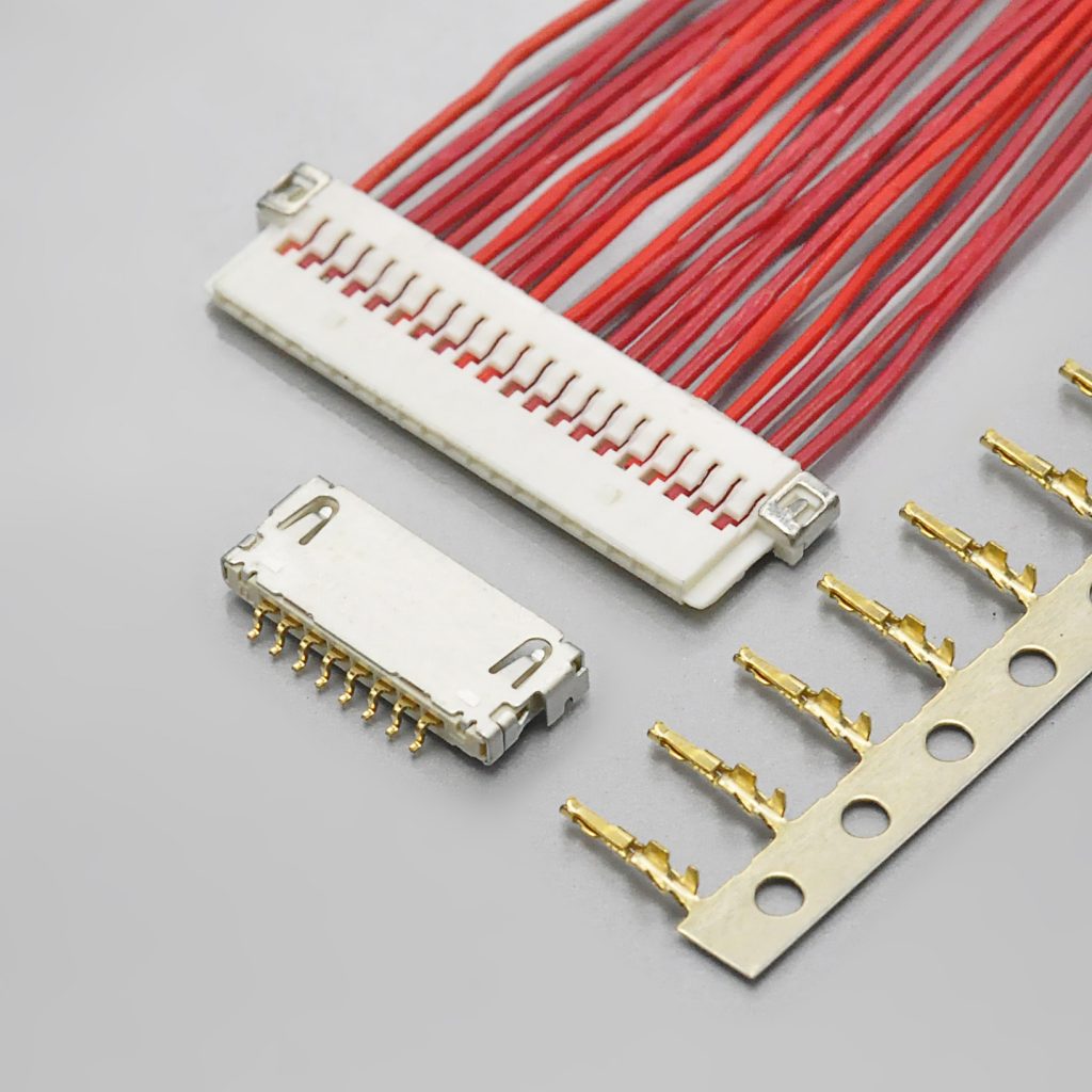
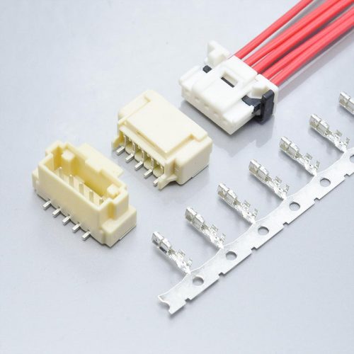
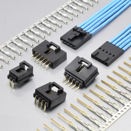
Figure 1 — KONNRA KR1002 series: 1.0mm pitch connector for the Hirose DF19 interface
➡️ View the KONNRA KR1002 Hirose DF19 Equivalent
A short glossary, because this series uses all four terms
- Receptacle — the board-mounted half, soldered to the PCB. In the DF19 numbering this is the part with a
Pin it (DF19G-20P-1H). - Plug — the cable-side half. In the numbering this is the part with an
S(DF19-20S-1C). - Discrete wire — ordinary insulated hook-up wire, crimped into a contact and inserted into a plug housing. The
CinDF19-20S-1Cmeans discrete wire. - FPC — flexible printed circuit, a flat ribbon of copper traces on polyimide. The
FinDF19G-20S-1Fmeans FPC. - Micro-coaxial cable — a very fine coaxial cable, here AWG #40. The
SDinDF19G-20S-1SDmeans micro-coax. - LVDS — low-voltage differential signalling, the high-speed interface family that display panels use to talk to a mainboard. Differential pairs need controlled impedance and a solid ground path, which is why the DF19’s grounding plates matter.
- Offset mounting — the receptacle body sits beside the board edge rather than on top of it, trading board area for a lower profile.
Hirose DF19 and KONNRA KR1002 Specifications
| Parameter | Hirose DF19 (Hirose documentation) | KONNRA KR1002 (KONNRA documentation) |
|---|---|---|
| Pitch | 1.0mm | 1.00mm |
| Row configuration | Single row | Single row |
| Connection type | Board-to-cable, board-to-FPC, board-to-micro-coax | Wire-to-Board |
| Positions | 8, 14, 20, 30 | 8 – 30 |
| Current rating | 1A at AWG #28; 0.9A at #30; 0.8A at #32; 0.5A at #36; 0.5A for FPC; 0.3A for AWG #40 micro-coax | 1A |
| Voltage rating | 100V AC | 100V |
| Operating temperature | −35°C to +85°C (including temperature rise from current flow) | −40°C to +105°C |
| Operating humidity | 20% to 80% | — |
| Insulation resistance | 500MΩ min. at 100V DC | 500MΩ min. |
| Withstanding voltage | 300V AC / one minute, no flashover or insulation breakdown | 500V AC / minute |
| Contact resistance | 30mΩ max. (50mΩ max. on the FPC path), measured at 100mA | 30mΩ max. |
| Insertion / extraction force | Min. 0.2N, max. 3N per contact (steel pin Ø0.2±0.005) | — |
| Durability | 30 insertion/withdrawal cycles | — |
| Vibration | No electrical discontinuity of 1μs or more — 10 to 55Hz, 0.75mm single amplitude, 2 hours in each of 3 directions | — |
| Humidity (steady state) | 96 hours at 40±2°C, 90–95% RH; contact resistance 30mΩ max, insulation resistance 500MΩ min | — |
| Temperature cycle | −55°C → +5 to +35°C → +85°C → +5 to +35°C, 5 cycles | — |
| Receptacle insulator | Polyamide, black or beige, UL94V-0 | PA66 / PA6T / UL94 |
| Receptacle contact | Phosphor bronze, gold plated | Phosphor bronze |
| Grounding plate | Phosphor bronze, tin plated or tin-copper plated | — |
| Plug insulator | Polyamide, beige | — |
| Micro-coax plug insulator | LCP, beige, UL94V-0 | — |
| Crimp contact | Phosphor bronze, gold plated | — |
| Plating | Gold plated (receptacle contacts and crimp contacts) | Gold flash / Tin over Nickel |
| Applicable discrete wire | AWG #28 (7/0.127mm), #30 (7/0.1mm), #32 (7/0.08mm) — jacket 0.5–0.6mm; AWG #36 (7/0.05mm) — jacket 0.27mm | Insulation O.D. 0.8mm max |
| Applicable micro-coax | AWG #40 (7/0.03mm) — jacket 0.3–0.4mm | — |
| Applicable FPC | t = 0.145±0.03mm | — |
| Recommended wire style | UL1571 (thin type) | — |
| Strip length | 1.2mm to 1.9mm | — |
| Mounting styles | Top-board (1.65mm high), offset K (1.0mm high), offset L (1.1mm high), reverse offset KR (1.0mm high), vertical | Right angle SMT |
| Approvals / compliance | RoHS; glow wire compliant to IEC60695-2-11 | RoHS compliant; UL94 |
| Tooling | Hirose-approved applicator and press required — non-approved tools void the warranty | — |
” — ” means the parameter is not stated in the manufacturer documentation reviewed for this guide. Confirm any blank against the current Hirose DF19 catalog and the KR1002 product specification before releasing a drawing.
The Feature That Defines the DF19: One Receptacle, Three Cable Systems
Most wire-to-board connectors accept exactly one kind of cable. The DF19 accepts three, and this is the single most important thing to understand before cross-referencing it.
| Plug type | Hirose plug part numbers | How it terminates | Rated current | Ground plate |
|---|---|---|---|---|
| Crimped discrete wire | DF19-…S-1C (no grounding plate) / DF19G-…S-1C(05) (with grounding plate) |
Insulated wire crimped into a contact, contact inserted into the plug housing | 1A at AWG #28 | Optional |
| FPC | DF19G-…S-1F(05) |
Flat flexible circuit folded into the plug | 0.5A | Required |
| Micro-coaxial cable | DF19G-…S-1SD(05) |
Fine coax soldered to the contact | 0.3A at AWG #40 | Required |
Two Hirose design rules sit behind this table:
- The same receptacle serves all three. Hirose states that the same receptacle will accept plugs terminated with discrete wire, FPC or micro-coaxial cable — so a board design can commit to one footprint and still leave the cable architecture open.
- The plug’s external dimensions do not change. Hirose states the plug assembly’s external dimensions remain the same whether it is terminated with discrete wire, FPC or micro-coaxial cable. A mechanical envelope validated for a crimped harness stays valid if the build changes to an FPC tail.
Hirose also requires grounding plates when terminating with FPC or micro-coaxial cable. These are separate line items — they are ordered as their own part numbers and installed with their own tooling.
Why this matters more than anything else when cross-referencing: a DF19 replacement is not one connector — it is an interface. If your design uses the discrete-wire path only, a crimp-style equivalent can cover it. If your design depends on the FPC or micro-coaxial path, the grounding plates and the plug bodies are part of the requirement, and they are not interchangeable with a housing and a terminal.
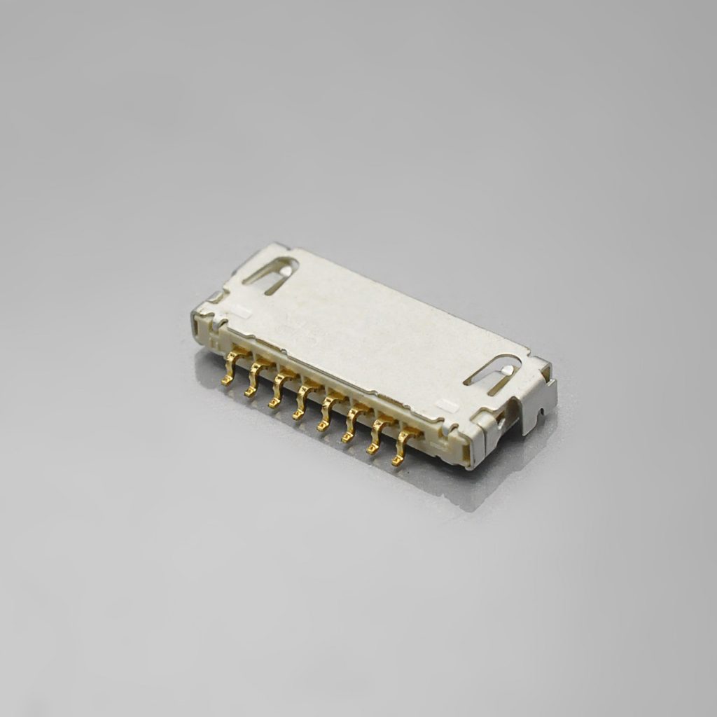
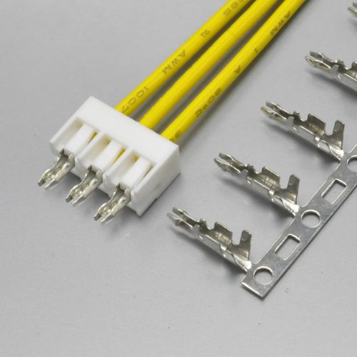
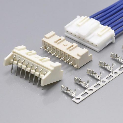
Figure 2 — KR1002 right-angle SMT wafer: the board-mounted half
Hirose DF19 Part Number Cross-Reference
| Hirose DF19 component | Hirose part numbers | KONNRA equivalent |
|---|---|---|
| Receptacle, top-board mounting (1.65mm high) | DF19G-8P-1H(54), DF19G-14P-1H(54), DF19G-20P-1H(54), DF19G-30P-1H(54) |
KR1002 right-angle SMT wafer |
| Receptacle, offset mounting (1.0mm high) | DF19K-20P-1H(54), DF19K-30P-1H(54) |
Confirm footprint |
| Receptacle, offset mounting (1.1mm high) | DF19L-14P-1H(54), DF19L-20P-1H(54), DF19L-30P-1H(54) |
Confirm footprint |
| Receptacle, reverse offset mounting (1.0mm high) | DF19KR-14P-1H(54), DF19KR-20P-1H(54) |
Confirm footprint |
| Receptacle, vertical | DF19-14P-1V(56), DF19-20P-1V(56) |
— |
| Plug, discrete wire, no grounding plate | DF19-8S-1C, DF19-14S-1C, DF19-20S-1C, DF19-30S-1C |
KR1002 housing |
| Plug, discrete wire, with grounding plate | DF19G-8S-1C(05), DF19G-14S-1C(05), DF19G-20S-1C(05), DF19G-30S-1C(05) |
Confirm grounding plate |
| Plug, FPC | DF19G-14S-1F(05), DF19G-20S-1F(05), DF19G-30S-1F(05) |
Not documented |
| Ground plate for FPC | DF19G-14S-1F-GND(05), DF19G-20S-1F-GND(05), DF19G-30S-1F-GND(05) |
Not documented |
| Plug, micro-coaxial cable | DF19G-14S-1SD(05), DF19G-20S-1SD(05) |
Not documented |
| Ground plate for micro-coaxial cable | DF19G-14S-1SD-GND, DF19G-20S-1SD-GND |
Not documented |
| Crimp contact, AWG #28–30 | DF19A-2830SCFA |
KR1002 terminal |
| Crimp contact, AWG #30–32 | DF19A-3032SCFA |
KR1002 terminal |
| Crimp contact, finest wire (36 AWG) | DF19A-3336SCFA |
KR1002 terminal |
How to read a DF19 part number
Every DF19 part number encodes the same seven fields. Reading them is what lets you confirm a cross-reference instead of guessing at it.
DF19 G - 20 P - 1 H (54)
| Field | Meaning |
|---|---|
DF19 |
Series name |
| Configuration | Receptacle: G = top-board mounting (1.65mm high); K = offset mounting (1.0mm high); L = offset mounting (1.1mm high); KR = reverse offset mounting (1.0mm high). Plug: a leading G means “with grounding plate”; blank means no grounding plate |
| Number of contacts | 8, 14, 20 or 30 |
| Connector type | S = plug, P = receptacle |
1 |
Contact pitch, 1mm |
| Mounting / termination type | H = horizontal SMT; V = vertical SMT; C = plug for discrete wire (crimp contact); F = plug for FPC; SD = plug for micro-coaxial cable |
| Packaging | (54) tape and reel, 1,000 pcs/reel · (05) bag, 100 pcs/pack · (56) tape and reel for the vertical receptacle |
A separate trailing GND denotes a ground plate ordered as its own line item.
The crimp contacts use their own numbering: DF19A - 2830 SCF A
| Field | Meaning |
|---|---|
DF19A |
Contact series |
2830 3032 3336 |
Conductor size — 28–30 AWG, 30–32 AWG, and 36 AWG respectively |
SCF |
Plug contact, tape and reel |
A |
Gold plating |
| Packaging suffix | Blank = 10,000 pcs/reel · (41) = 20,000 pcs/reel |
One trap in this numbering: the
Gprefix means two different things depending on the connector type. On a receptacle (DF19G-20P-1H) it means top-board mounting. On a plug (DF19G-20S-1C) it means the grounding plate is fitted. ReadingDF19Gas a single concept across both is the most common part-number error on this series.
Pin counts: only four are offered
Hirose lists the DF19 in four contact counts: 8, 14, 20 and 30. The receptacle’s “A” dimension — the distance across the contact field — scales exactly with the count at 1.0mm per position.
| Contacts | Receptacle A | Discrete-wire plug A |
|---|---|---|
| 8 | 11.55mm | 11.5mm |
| 14 | 17.55mm | 17.5mm |
| 20 | 23.55mm | 23.5mm |
| 30 | 33.55mm | 33.5mm |
The offset and vertical styles follow the same 1.0mm step, from a different base:
| Contacts | DF19K (1.0mm high) |
DF19L (1.1mm high) |
DF19KR (reverse) |
DF19-…-1V (vertical) |
|---|---|---|---|---|
| 14 | — | 17.55mm | 17.55mm | 17.9mm |
| 20 | 23.55mm | 23.55mm | 23.55mm | 23.9mm |
| 30 | 33.55mm | 33.55mm | — | — |
The arithmetic is a useful cross-check: for every through-board style, the receptacle A dimension is 3.55mm + (number of contacts × 1.0mm). Applied to the table above it reproduces 11.55, 17.55, 23.55 and 33.55mm exactly. If a drawing or a quotation quotes a different A dimension for a given contact count, one of the two numbers is wrong.
Note on KONNRA’s range. KONNRA documents the KR1002 from 8 to 30 circuits. Hirose catalogues exactly four counts in that span. If your build calls for an intermediate count — say 16 or 24 — confirm availability in writing rather than assuming a continuous range.
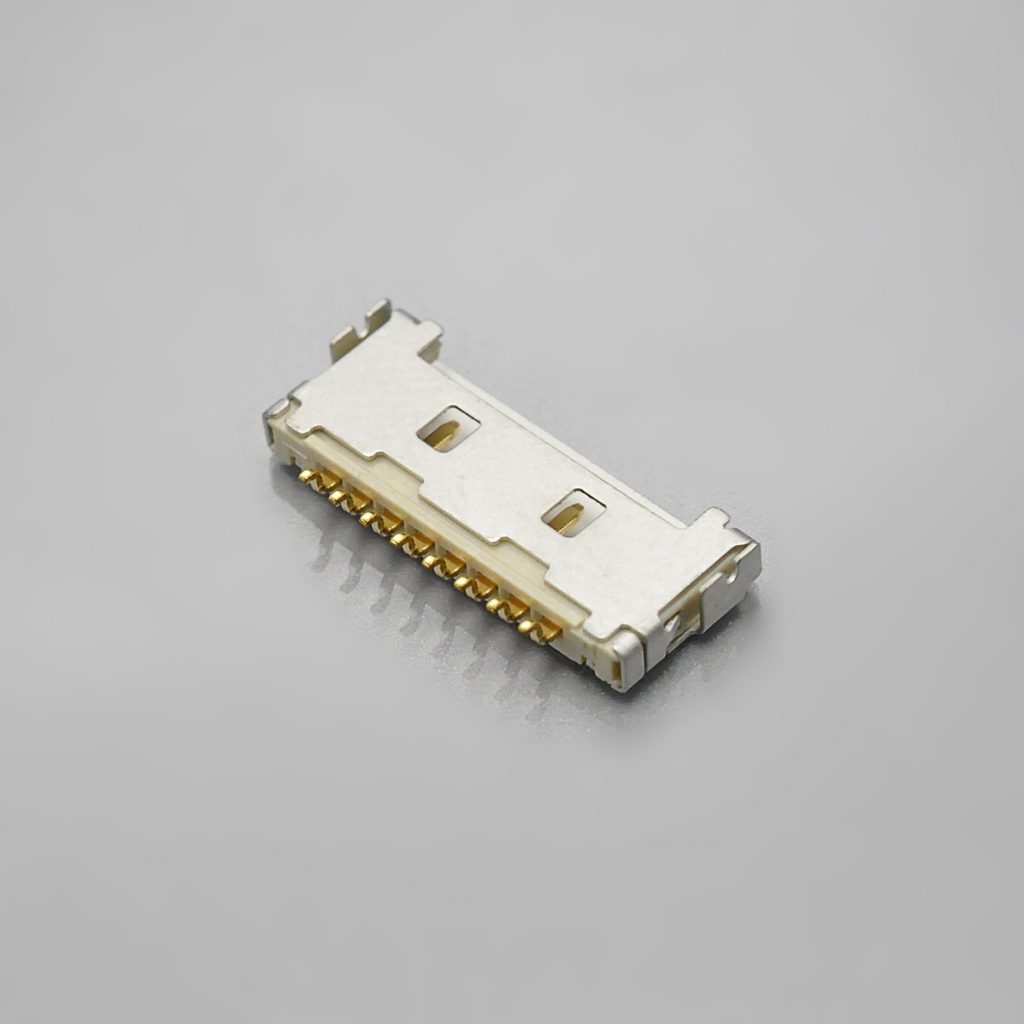
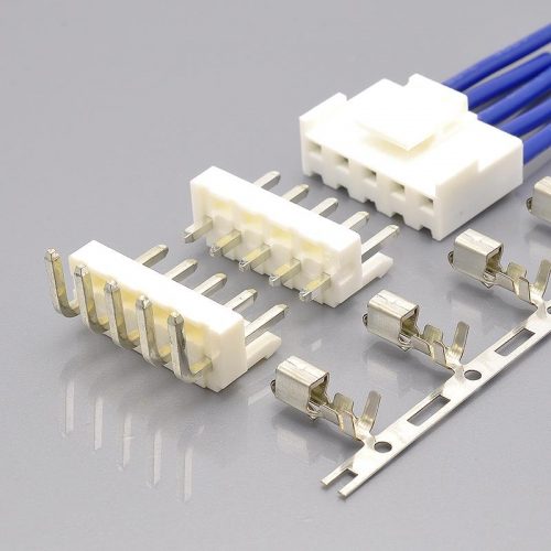
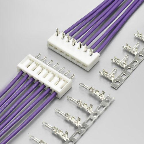
Figure 3 — KR1002 single-row wafer
The DF19 Current Rating Depends on Your Wire, Not on the Connector
This is the specification most often quoted wrongly, because the DF19 does not have a single current rating. It has six.
| Termination | Conductor | Rated current |
|---|---|---|
| Discrete wire | AWG #28 (7/0.127mm) | 1.0A |
| Discrete wire | AWG #30 (7/0.1mm) | 0.9A |
| Discrete wire | AWG #32 (7/0.08mm) | 0.8A |
| Discrete wire | AWG #36 (7/0.05mm) | 0.5A |
| FPC | t = 0.145±0.03mm | 0.5A |
| Micro-coaxial cable | AWG #40 (7/0.03mm) | 0.3A |
Why the rating moves. A 1.0mm pitch contact has a fixed contact area, but the current the circuit can carry is set by the conductor feeding it. At AWG #28 the contact is the limiting element and the rating is 1A. As the conductor gets finer, the wire becomes the bottleneck, and Hirose’s published rating falls with it — 0.9A at #30, 0.8A at #32, and 0.5A at #36. Terminate with FPC or micro-coax and the conductor cross-section drops again, to 0.5A and 0.3A.
What this means in practice. A catalogue or a cross-reference table that lists the DF19 as “1A” is quoting the AWG #28 figure. That number is correct — for AWG #28. If your harness is built with AWG #32, the applicable rating is 0.8A, and a design that assumed 1A has no margin at all. If you are driving a backlight or a panel supply rail through an FPC tail, the applicable figure is 0.5A.
KONNRA documents the KR1002 at 1A. That matches Hirose’s AWG #28 figure. Before you release a design, tell us your actual wire gauge and termination type, and we will confirm the applicable rating for that combination rather than the headline number.
➡️ Send us your wire gauge and we will confirm the applicable current rating
Mounting Styles: Four Ways to Land the Same Interface on the Board
Hirose offers the DF19 receptacle in four right-angle configurations and one vertical, and the choice is driven almost entirely by how much board height you have.
| Mounting style | Part prefix | Board height | Contacts offered | What it is for |
|---|---|---|---|---|
| Top-board mounting | DF19G-…-1H(54) |
1.65mm | 8, 14, 20, 30 | Standard right-angle receptacle sitting on top of the board |
| Offset mounting | DF19K-…-1H(54) |
1.0mm | 20, 30 | Lowers the profile by moving the receptacle to the board edge |
| Offset mounting | DF19L-…-1H(54) |
1.1mm | 14, 20, 30 | As above, 0.1mm taller |
| Reverse offset mounting | DF19KR-…-1H(54) |
1.0mm | 14, 20 | Mirror of DF19K, for the opposite side of the board |
| Vertical | DF19-…-1V(56) |
Vertical | 14, 20 | Cable exits perpendicular to the board |
Three practical notes on these styles.
- The offset styles place part of the assembly over the board edge. Hirose’s mounting patterns for these variants show the plug envelope extending beyond the receptacle outline, so both the board edge clearance and the volume in front of the connector have to be checked — not just the footprint.
- Hirose marks a keep-out under the receptacle. The recommended mounting pattern carries an explicit “No conductive traces” note under the connector outline. Plan the ground pour and the differential-pair routing around it.
- The vertical style uses different packaging. The
(56)suffix is tape and reel for the vertical receptacle, at 400mm reel diameter — different from the(54)reel used by the right-angle styles.
What KONNRA documents is a right-angle SMT wafer. If your design uses one of the offset or reverse-offset footprints, send the Hirose part number and we will confirm which KR1002 wafer geometry corresponds before you commit tooling.
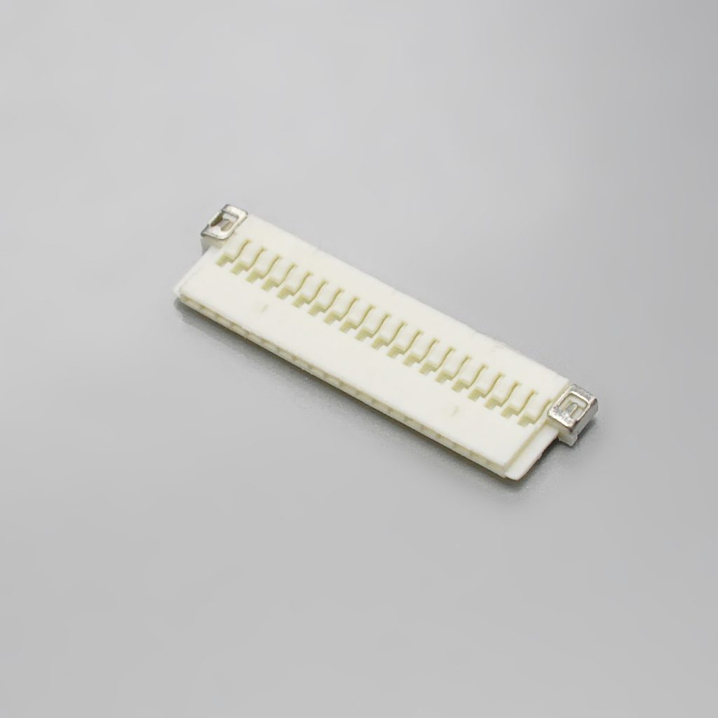
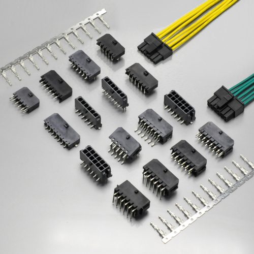
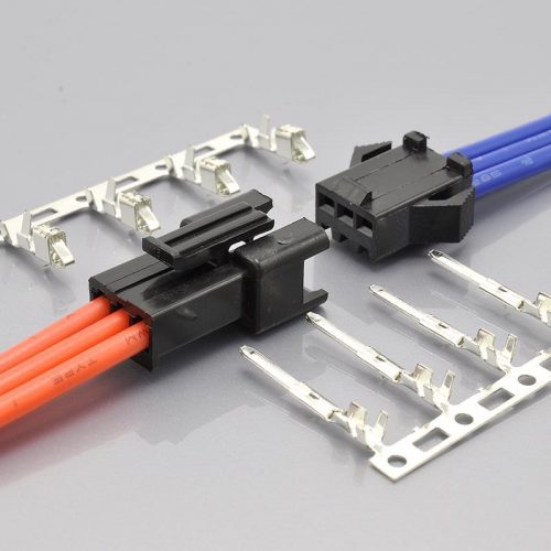
Figure 4 — KR1002 1.00mm pitch housing
Crimp Contacts, Applicable Wire and Tooling
The DF19 discrete-wire path uses one of three crimp contacts, selected by conductor size.
| Crimp contact | Conductor size | Packaging | Plating |
|---|---|---|---|
DF19A-2830SCFA |
28 to 30 AWG | Tape and reel | Gold |
DF19A-3032SCFA |
30 to 32 AWG | Tape and reel | Gold |
DF19A-3336SCFA |
Fine wire (36 AWG) | Tape and reel | Gold |
The contacts overlap on 30 AWG, so a 30 AWG conductor can be crimped into either the 2830 or the 3032 contact. Which one is correct depends on the strand construction of your specific cable, not on the gauge alone.
Applicable cable
Hirose specifies the cable narrowly, and this is one place where a “close enough” wire causes field failures.
| Wire size | Conductor construction | Jacket diameter |
|---|---|---|
| 28 AWG | 7/0.127mm | 0.5mm to 0.6mm |
| 30 AWG | 7/0.1mm | 0.5mm to 0.6mm |
| 32 AWG | 7/0.08mm | 0.5mm to 0.6mm |
| 36 AWG | 7/0.05mm | 0.27mm |
| 40 AWG (micro-coaxial) | 7/0.03mm | 0.3mm to 0.4mm |
The conductor must be tin-plated stranded annealed copper. Hirose’s application notes state that solid wire, wires with polyester threads and tin-coated wire should not be crimped. The recommended cable style is UL1571 (thin type) — and Hirose notes that you should contact them when using 36 AWG. Hirose explicitly adds: when using wire other than the recommended types, contact the manufacturer’s representative.
Strip length is 1.2mm to 1.9mm. Outside that window the crimp either loses conductor strands or bites into insulation.
Tooling — and why it is not optional
Hirose specifies its own tooling combination for this series:
| Tool | Part number |
|---|---|
| Applicator | AP105-DF19S |
| Press unit | CM-105C |
| Grounding plate tool, 14 pos. | DF19G-14S/PR-MD2 |
| Grounding plate tool, 20 pos. | DF19G-20S/PR-MD2 |
| Grounding plate tool, 30 pos. | DF19G-30S/PR-MD2 |
Hirose states that use of tools other than approved Hirose Electric tools will void the product warranties, and that the product is not guaranteed unless Hirose-approved tools are used. The FPC termination path additionally requires dedicated assembly fixtures at each stage of the process.
If you build harnesses in-house, this constrains you to Hirose’s crimp tooling — or to a supplier who has it. If you buy finished assemblies, the tooling question becomes the supplier’s, and it is worth asking directly.
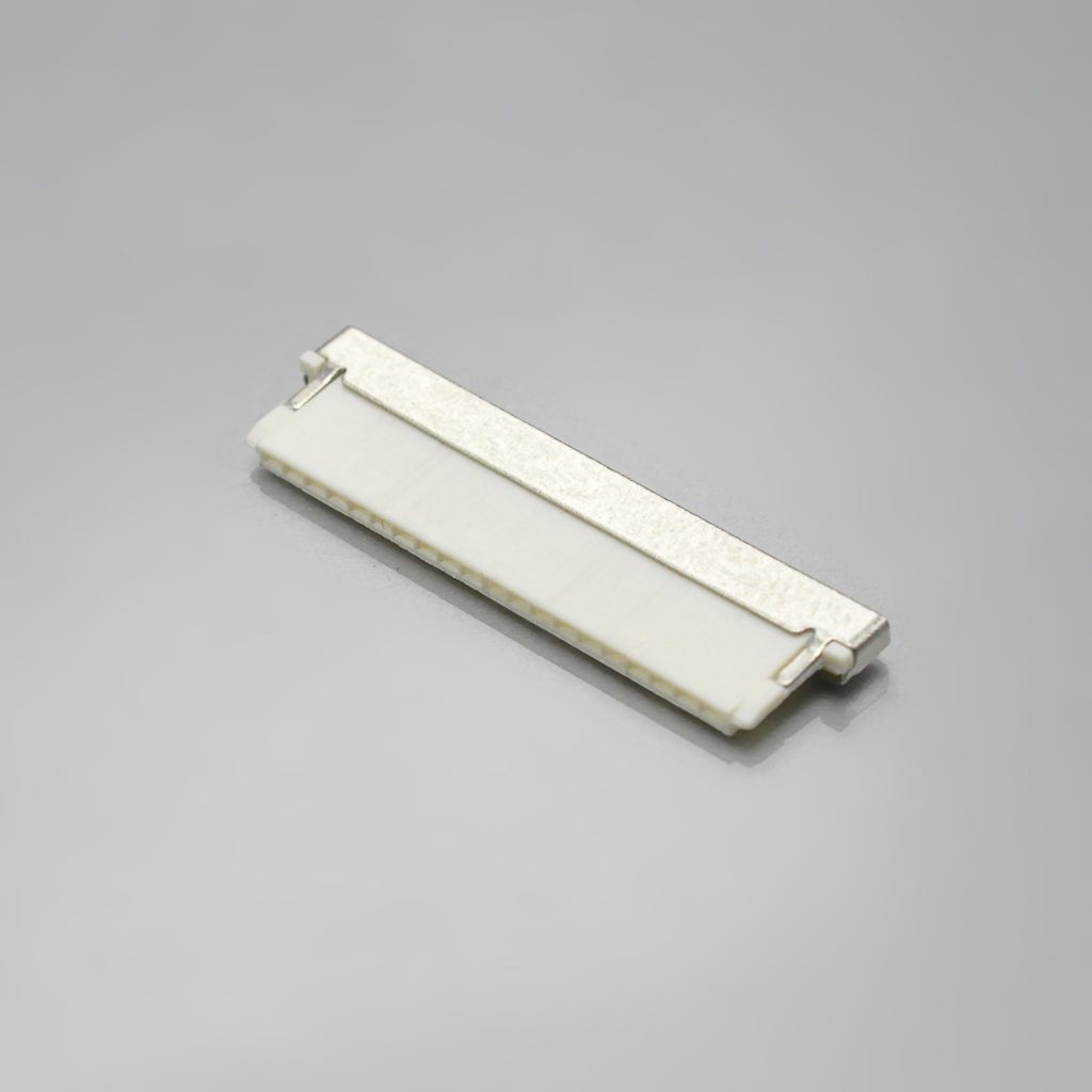
Figure 5 — KR1002 single-row housing

Figure 6 — KR1002 crimp terminal for the 1.0mm pitch DF19 interface
Series documentation
- KR1002 series engineering drawing (PDF)
- KR1002 product specification (PDF)
- KR1002 package specification (PDF)
Specification Differences to Verify Before You Cross-Reference
Ten points deserve attention before you sign off a DF19 cross-reference.
- The current rating is one figure on the KONNRA side and six on the Hirose side. Hirose publishes a rating per termination type and wire gauge; KONNRA publishes a single 1A. That 1A is the AWG #28 figure. If your harness uses AWG #32 or an FPC tail, the applicable rating is 0.8A or 0.5A. This is the most consequential difference in the whole comparison.
- Contact plating is described differently. Hirose lists gold-plated contacts for both the receptacle and the crimp contact. KONNRA documents gold flash / tin over nickel. Gold flash is a thin gold deposit rather than a full gold plating, and the two are not equivalent in thickness or in long-term contact stability. Neither document states a thickness in microns — so ask for the figure if contact finish matters to your qualification.
- The 3-in-1 interface is only partly covered on the KONNRA side. KONNRA documents a right-angle wafer, a housing and a terminal — the discrete-wire route. No FPC plug, micro-coax plug or grounding plate is documented. If your design uses those paths, they need to be confirmed or sourced separately.
- Durability is 30 mating cycles on the Hirose side, and unpublished on the KONNRA side. Hirose’s rated durability for the DF19 is 30 insertion/withdrawal cycles. That is a low number for a connector in a product that may be serviced. Design so the display connector is not the one being cycled, and if your service model depends on re-mating, ask for cycle data.
- Withstanding voltage differs — 300V AC versus 500V AC. Hirose specifies 300V AC for one minute with no flashover or insulation breakdown. KONNRA documents 500V AC per minute. The KONNRA figure is the higher one here, which is the reverse of the usual pattern — confirm the test basis (applied between which points, for how long, on which variant).
- Operating temperature is claimed wider on the KONNRA side. Hirose specifies −35°C to +85°C, and states that figure includes the temperature rise caused by current flow. KONNRA documents −40°C to +105°C. If your application genuinely relies on operation above +85°C, request the test data rather than accepting the headline range.
- Position counts: four discrete counts versus a 8–30 range. Hirose catalogues 8, 14, 20 and 30 contacts. KONNRA documents 8–30 circuits. Confirm which counts are tooled before a drawing depends on an intermediate count.
- The ground path runs through the grounding plates. Hirose’s ground connection works through metal grounding plates bonded to the shell, and Hirose requires grounding plates when terminating with FPC or micro-coaxial cable. They are not documented on the KONNRA side. On a differential interface the ground return is part of the signal-integrity budget, so this has to be settled before qualification.
- Tooling and warranty implications. Hirose requires the approved applicator and press, and states non-approved tooling voids the warranty. KONNRA does not document crimp tooling for the KR1002 terminal. Ask which applicator and press the terminal is validated against.
- Applicable wire is specified narrowly by Hirose and loosely by KONNRA. Hirose accepts jacket diameters of 0.5–0.6mm for 28–32 AWG and 0.27mm for 36 AWG, requires tin-plated annealed stranded conductor, and recommends UL1571 thin-wall cable. KONNRA documents insulation O.D. 0.8mm max — wider than any Hirose-compliant cable. Hirose-compliant cable therefore sits inside the KONNRA window, but heavier insulation that would fail Hirose’s specification still passes KONNRA’s. Pin the accepted dimensions to the drawing for your specific assembly.
What the Hirose DF19 Is Used For
Hirose states the DF19 is accepted by the industry and market as the de facto standard for LCD panel connections, specifically panels under 12 inches, and describes it as a high-performance connector for LVDS high-speed differential signals. Hirose lists its applications as LCD connections in small consumer devices — digital cameras, notebook computers and PDAs — and, more generally, any device requiring high-density interconnection for consistent high-speed data rates.
| Application | Why the DF19 fits |
|---|---|
| Display panel to mainboard in laptops, tablets and handhelds | The series was designed around panel connections under 12 inches, at 1.0mm pitch with a 1.0mm mounting height option |
| LVDS differential pairs | Specified for high-speed differential signalling, with a metal-shell ground path rather than a single ground pin |
| Compact devices where board height is the binding constraint | The offset styles get the receptacle down to 1.0mm above the board |
| Products that ship in more than one cable configuration | The same receptacle accepts a crimped harness, an FPC tail or a micro-coax assembly |
| Short signal runs inside a fold or a hinge | The FPC and micro-coaxial cable paths exist for exactly the places a round cable will not go |
| Industrial HMI and touch panels | The same panel-interface standard carries over to fixed equipment with an LVDS display module |
| POS terminals, portable instruments and monitors | Where a small LVDS panel meets a mainboard and the harness is built to order |
| Medical and instrumentation front panels | Supported by KONNRA’s ISO13485 medical device quality system where the product falls in that scope |
What the DF19 is not for. It is not a power connector. At 0.3–1.0A depending on wire and termination, it carries signal and modest supply current, not motor or lighting loads. If your design needs more than 1A, the answer is a different pitch class rather than a different DF19 variant.
Cable assembly options
KONNRA builds assemblies on the KR1002 interface in the standard harness configurations:
| Cable type | Description | Typical use |
|---|---|---|
| Single-headed | Housing on one end, bare wire leads on the other | Pigtail from a panel socket to a termination block |
| Same-side-head | Housing on both ends, same orientation | Extending a display harness |
| Reverse-side-head | Housing on both ends, reversed orientation | Routing a harness through a hinge or fold |
| Adapter and transition cables | KR1002 on one end, another interface on the other — for example DF19 to JST SH, or DF19 to a larger-pitch board connector | Where one board uses a DF19 receptacle and the other end does not |
DF19-to-SH adapter harnesses are a common request, because both interfaces sit at 1.0mm pitch and both appear in the same products. They are not intermateable, so the conversion has to happen in the cable. KONNRA’s harness division builds these to order.
Connector lead time is typically 2–3 weeks; wiring harness lead time is typically 3–4 weeks.
➡️ Explore KONNRA wiring harness capabilities
DF19 vs the Other Hirose 1.0mm and 1.25mm Series
“1.0mm pitch” does not identify a connector. Hirose alone sells four series at that pitch, plus two at 1.25mm, and none of them mate with each other. The table below uses Hirose’s own published series data.
| Series | Pitch | Positions available | Wire sizes | Max current | KONNRA equivalent |
|---|---|---|---|---|---|
| DF19 | 1.0mm | Single row 8, 14, 20, 30 | #36, #32, #30, #28 | 0.5A to 1.0A by gauge | KR1002 |
| DF20 | 1.0mm | Double row 10, 20, 30, 40, 50 | #36, #32, #30, #28 | 0.3A to 1.0A by gauge | — |
| DF50 | 1.0mm | Single row 2–16; double row 20, 30, 40, 50 | #30, #28 | 1.0A | — |
| FX15 | 1.0mm | Single row 21, 31, 41, 51 | #32, #30, #28 | 0.5A | — |
| DF13 | 1.25mm | Single row 2–15; double row 10, 20, 30, 40 | #32, #30, #28, #26 | 1.0A | KR1256 |
| DF14 | 1.25mm | Single row 2–10, 15, 20, 25, 30 | #32, #30, #28, #26 | 1.0A | — |
What this table shows.
- Only the DF19 and the FX15 are built around display and LVDS signalling. Hirose positions the FX15 for FPD displays and televisions with a wide self-alignment range; the DF19 is the panel-under-12-inches standard. If your design is a display link, these are the two candidates.
- The DF50 is a locking general-purpose connector, not a display interface — it prioritises a metal lock with a tactile click and wrenching resistance over the three-way interface.
- The DF20 is a double-row low-profile board connector with a mated height of 5.8mm above the PCB — a different mechanical problem.
- The DF19 is the series where a single receptacle takes all three termination types, and where Hirose states the plug’s external dimensions stay constant across discrete wire, FPC and micro-coax. That is what makes it a design decision rather than just a part number.
- KONNRA’s published cross-reference range covers the DF19 and DF13 — as KR1002 and KR1256 respectively. For DF14, DF20, DF50 and FX15, KONNRA’s 1.0mm and 1.25mm range is built around other series (KR1000 for JST SH, KR1005, KR1007, KR1012 and the FPC range). If your design uses one of those Hirose series, send the part number and we will tell you what is available rather than guess.
➡️ Explore the full 1.0mm pitch range · HIROSE alternatives connector range
A note on JST SH, since it shares the pitch
JST’s SH 1.0 series and the Hirose DF19 are both 1.0mm pitch, both single row, and both appear in small display-bearing products. They are different interfaces with different mating geometry and they do not mate. KONNRA’s cross-reference range reflects the symmetry — KR1000 for JST SH, KR1002 for Hirose DF19 — but the two are not substitutes for one another.
Cross-reference on the part number. At this pitch, pitch and appearance will not tell you which connector you are holding.
Sourcing the Hirose DF19: What Procurement Teams Ask
Engineering decides that a connector will work. Procurement decides whether the supply chain around it is safe.
“Can you be a second source without changing our design?” That is what a documented cross-reference is for. The KR1002 is specified against the Hirose DF19 at 1.0mm pitch in a right-angle SMT wafer with housing and crimp terminal. We confirm equivalence against your specific part number, because position count, mounting style and termination type all change the answer.
“What are your lead times?” Connector production lead time is typically 2–3 weeks. Wiring harness lead time is typically 3–4 weeks. Key materials are prestocked.
“How long for samples?” Complete connector set samples can be delivered within 45 days. Sample harnesses can be supplied from the same process used in production, which matters on a 1.0mm pitch part where the crimp quality is most of the reliability.
“What qualifications do you hold?” ISO9001, ISO14001, IATF16949, ISO45001:2018, ISO13485, IPC620, and UL product and operational safety certifications. Automotive-grade series additionally hold LV214 and US CAR-2.
“How do we know the parts match your documentation?” A CNAS-accredited laboratory with 45+ sets of precision testing instruments, with dimensional and electrical verification data available on request. 95% of production processes carry full-line intelligent visual CCD inspection; automotive series receive 100% CCD inspection.
“Are you a manufacturer or a trader?” A manufacturer. Dongguan Konnra Electronics Co., Ltd., founded 2004, with in-house mould design, injection moulding, stamping, assembly, and inspection — so the connector and the cable assembly come from one quality system.
“What volumes can you support?” KONNRA reported 2025 sales of RMB 310 million, with connectors at 60% and wiring harnesses at 40% of the product mix, across four production bases with automation coverage exceeding 95%.
“Who else buys from you?” KONNRA states that it serves global cooperative clients including BYD, Volkswagen, and DJI.
➡️ Request the vendor qualification pack — certificates, test capability summary, product drawings, and a sample plan in one enquiry.
How to Get a Cross-Reference Check on Your DF19 Part Number
Most DF19 sourcing enquiries stall on the same thing: the buyer is not sure what information the supplier needs, so the enquiry never gets sent. Here is the complete list.
Send us:
- The original Hirose part number, if you have it — for example
DF19G-20P-1H(54),DF19-20S-1C,DF19G-20S-1F(05), or the contactDF19A-2830SCFA - Position count — and remember there are only four: 8, 14, 20, 30
- Mounting style — top-board (
G), offset (K/L), reverse offset (KR), or vertical (V) - Termination type — discrete wire (
C), FPC (F), or micro-coaxial cable (SD) - Wire specification — gauge, strand construction and jacket diameter. Hirose specifies jacket diameters of 0.5–0.6mm for 28–32 AWG, so the jacket diameter is not optional information on this series
- Whether a grounding plate is required — it is mandatory for the FPC and micro-coax paths, and it is a separate line item
- Application, annual volume and whether you buy connectors or finished harnesses
- A drawing or photo if the part number is unreadable or the design has been reverse-engineered
When you send a part number, we will confirm three things against Hirose’s own documentation: the applicable current rating for your wire and termination, the mounting footprint your suffix corresponds to, and whether the FPC or micro-coax path you may need is covered. Those are the three places a DF19 cross-reference most often goes wrong.
What you get back: a mapped KONNRA part number with the relevant product and engineering drawings, a specification comparison against your original part, and a sample and quote plan.
Engineer’s Pre-Release Checklist
Run this before you release a drawing for a DF19-family connector.
- Series confirmed by part number, not by pitch. DF19, DF20, DF50 and FX15 are all 1.0mm; DF13 and DF14 are 1.25mm. None of them mate.
- Brand confirmed. The DF19 is a Hirose series — there is no JST DF19. If your drawing says “JST DF19”, the drawing is wrong and the part number should be resolved before anything is ordered.
- Termination type decided — discrete wire, FPC or micro-coaxial — and the plug part number matches it:
C,F,SD. - Grounding plate specified if the design uses the FPC or micro-coax path. It is required, and it is a separate line item with its own tooling.
- Current rating checked against your actual wire, not the headline 1A. AWG #32 gives 0.8A, AWG #36 and FPC give 0.5A, AWG #40 micro-coax gives 0.3A.
- Mating cycle count accepted — the rated durability is 30 cycles. If your service model needs more, that is a design change, not a sourcing change.
- Mounting style and board height confirmed — 1.65mm for top-board, 1.0mm or 1.1mm for the offset styles. Check the plug envelope as well as the receptacle footprint, since the offset styles overhang the board edge.
- The “no conductive traces” keep-out under the receptacle is respected in the copper pour.
- Jacket diameter inside the specification for the wire you intend to use — 0.5–0.6mm for 28–32 AWG, 0.27mm for 36 AWG, 0.3–0.4mm for 40 AWG micro-coax.
- Strip length set to 1.2–1.9mm in the harness drawing.
- Crimp tooling identified. Hirose requires its approved applicator and press, and states that other tooling voids the warranty. If you are building in-house, confirm you have it or ask us which tooling the KR1002 terminal is validated against.
- Soldering profile checked. Hirose’s recommended reflow allows up to 2 cycles; manual soldering is quoted as a soldering iron at 290±10°C for 3 seconds in the use recommendations (the specification table states 300°C for 3 seconds — confirm which figure your process assumes). Screen thickness 0.15mm, and board warpage within 0.03mm at the connector centre.
➡️ Send us your drawing. We will review it against the KR1002 specification and come back with any mismatch we find — before you commit tooling. Submit a drawing for review
Why Source DF19 Connectors from KONNRA
Dongguan Konnra Electronics Co., Ltd. (brand: KONNRA) was founded in 2004 and is a National High-Tech Enterprise specialising in connector and wiring harness research, development, production, and sales.
Manufacturing depth. A vertically integrated process covering precision mould design and manufacturing, automation design, precision injection moulding, stamping, assembly, and CCD visual inspection. Automation coverage exceeds 95% across production lines.
Testing and validation. A CNAS-accredited laboratory with 45+ sets of precision testing instruments, and CAE analysis — contact nonlinear analysis, material nonlinear analysis, motion simulation, thermal field analysis, and high-frequency analysis — performed in Ansys 2022 R1. Verification data is available on request.
Inspection coverage. Full-line intelligent visual CCD inspection covers 95% of production processes, using Mitsubishi and Panasonic PLC control systems with FA25–35mm optical lenses and 5-megapixel cameras. Automotive connector series receive 100% CCD visual inspection.
Quality systems. ISO9001, ISO14001, IATF16949, ISO45001:2018, ISO13485, IPC620, and UL product and operational safety certifications, with automotive-grade series additionally certified to LV214 and US CAR-2.
Capacity and delivery. Production bases in Dongguan Wangniudun (30,000 m², 350+ employees), Dongguan Changan (10,000 m², 150+ employees), and Hunan Daoxian (2,600 m², 100+ employees), with regional offices in Beijing, Chongqing, Hunan, Shanghai, and Kunshan. Key materials are prestocked, and complete connector set samples can be delivered within 45 days. KONNRA reported 2025 sales of RMB 310 million, with connectors at 60% and wiring harnesses at 40% of the product mix, and has served global cooperative clients including BYD, Volkswagen, and DJI.
Custom and joint R&D. Where a standard part does not fit — an unterminated position count, a specific mounting height, or a harness that has to transition between two interfaces — KONNRA supports customer joint R&D customisation.
How to Identify Whether Your Connector Is a DF19
If you are holding a connector and a drawing you cannot match, work through these in order:
- Measure the pitch — centre-to-centre between adjacent contacts. 1.0mm points at DF19, DF20, DF50 or FX15 (Hirose) or SH (JST). 1.25mm points at DF13 or DF14.
- Count the positions. The DF19 comes in 8, 14, 20 or 30 only. A 16 or 24 position connector at 1.0mm is not a DF19.
- Measure the contact field width. For a DF19 receptacle the “A” dimension is 3.55mm + (positions × 1.0mm) — so 11.55mm at 8 positions, 17.55mm at 14, 23.55mm at 20 and 33.55mm at 30. A contact field that does not reproduce this is a different series.
- Measure the height above the board. 1.65mm indicates top-board mounting; 1.0mm or 1.1mm indicates an offset style.
- Look for a metal grounding plate. If one is fitted, the part number will carry a
G(on plugs) and the assembly is set up for shielded or differential use. - Check the plug. A DF19 receptacle accepts a crimped housing, an FPC plug or a micro-coax plug. If the mating half looks like none of those, it is not a DF19.
If you are still unsure, photograph the connector next to a ruler, with the part number markings visible if any, and send it to us. On a 1.0mm pitch part a photo identifies the pitch reliably; the part number identifies the series.
Frequently Asked Questions
What is a Hirose DF19 connector?
A 1.0mm pitch, single-row, low-profile wire-to-board connector supplied in 8, 14, 20 and 30 contacts. Hirose describes it as the de facto standard for LCD panel connections on panels under 12 inches, and as a high-performance connector for LVDS high-speed differential signals. Its distinguishing feature is that one receptacle accepts three plug types — crimped discrete wire, FPC, or micro-coaxial cable — with the plug’s external dimensions staying the same across all three. It is rated 100V AC, with current ratings of 1A (AWG #28), 0.9A (#30), 0.8A (#32), 0.5A (#36), 0.5A (FPC) and 0.3A (AWG #40 micro-coax).
Is the DF19 a JST connector?
No. The DF19 is a Hirose Electric series. There is no JST series designated DF19. The mix-up is common because small wire-to-board connectors from both brands are used side by side and are informally called “JST connectors” — JST stands for Japan Solderless Terminal — and because Hirose’s DF19 and JST’s SH are both 1.0mm pitch. They are not intermateable.
What is the KONNRA equivalent of the Hirose DF19?
The KONNRA KR1002 series — a 1.0mm pitch wire-to-board connector documented from 8 to 30 circuits at 1A and 100V, offered as a right-angle SMT wafer with a housing and a crimp terminal.
How many pins does the DF19 have?
Four counts only: 8, 14, 20 and 30 contacts. Hirose catalogs no intermediate counts. The contact field width follows a fixed rule — 3.55mm plus 1.0mm per position — so a 20-position DF19 receptacle measures 23.55mm across the contacts.
What is the current rating of the DF19?
It depends on your wire and termination, and there is no single figure. Hirose specifies 1.0A with AWG #28, 0.9A with #30, 0.8A with #32, 0.5A with #36, 0.5A for FPC, and 0.3A for AWG #40 micro-coaxial cable. A source that quotes the DF19 as plain “1A” is quoting the AWG #28 figure only.
What wire does the DF19 use?
Tin-plated stranded annealed copper, with UL1571 (thin type) as the recommended cable style. Jacket diameters are 0.5 to 0.6mm for 28, 30 and 32 AWG, 0.27mm for 36 AWG, and 0.3 to 0.4mm for 40 AWG micro-coaxial cable. Strip length is 1.2mm to 1.9mm. Hirose’s application notes state that solid wire, wire with polyester threads and tin-coated wire should not be crimped.
Can the DF19 connect to an FPC?
Yes — that is one of its three termination paths. An FPC plug (DF19G-…S-1F(05)) folds the flat cable into the plug and mates with the same receptacle used for crimped wire. Two constraints apply: the FPC path is rated 0.5A rather than 1A, and a grounding plate is required (DF19G-…S-1F-GND(05)), ordered as a separate line item. FPC termination also needs dedicated assembly fixtures.
What is the difference between DF19 and DF19A?
DF19A is the crimp contact designation used within the DF19 series — for example DF19A-2830SCFA. It is not a separate connector. The catalog reviewed for this guide lists only DF19A contacts; if a drawing references a non-A DF19 contact, confirm it against the current Hirose catalog, since contact designations have been revised over the life of the series.
What is the difference between DF19 and JST SH?
Brand, mating geometry and application. DF19 is Hirose, 1.0mm pitch, 8/14/20/30 positions, and built for LVDS display links with a three-way interface. JST SH is JST, 1.0mm pitch, and a general compact wire-to-board connector. They do not mate. KONNRA’s equivalents are KR1002 for DF19 and KR1000 for JST SH. Converting between them requires an adapter harness.
What is the DF19’s mating durability?
30 insertion/withdrawal cycles, as specified by Hirose, with contact resistance held to 30mΩ max afterwards. That is a low figure for a connector that might be expected to survive field service, so design the assembly so the display connector is not the one being repeatedly cycled.
What mounting styles are available?
Five. Top-board mounting (DF19G) at 1.65mm above the board in 8, 14, 20 and 30 positions; offset mounting at 1.0mm (DF19K) or 1.1mm (DF19L); reverse offset mounting (DF19KR) at 1.0mm; and a vertical receptacle (DF19-…-1V). The offset styles place part of the assembly over the board edge, so the plug envelope and the board edge clearance both need checking.
Can I use non-Hirose crimp tools on the DF19?
Hirose states that use of tools other than approved Hirose Electric tools will void the product warranties, and that the product is not guaranteed unless Hirose-approved tools are used. The approved combination for this series is the AP105-DF19S applicator with the CM-105C press unit. If you build harnesses in-house this constrains your tooling; if you buy finished harnesses it becomes a question to ask your supplier.
Where is the DF19 used?
Primarily LCD display panel connections on panels under 12 inches, and any high-density interconnection carrying high-speed differential data. Hirose lists digital cameras, notebook computers and PDAs. In current practice the same interface appears in laptop and tablet panels, industrial HMI and touch panels, POS terminals, handheld instruments and medical monitors — anywhere an LVDS display module meets a mainboard.
How long does it take to get samples?
KONNRA can deliver complete connector set samples within 45 days. Connector production lead time is typically 2–3 weeks and wiring harness lead time typically 3–4 weeks.
Start Your Cross-Reference Check
KONNRA supplies the KR1002 series as individual components or as complete pre-crimped cable assemblies, and builds adapter and transition harnesses to order.
- Request a quote — KR1002 pricing, MOQ and configuration options for your position count, mounting style and termination type
- Request a sample — complete connector set samples within 45 days
- Request cross-reference verification — confirm KR1002-to-Hirose-DF19 equivalence against your specific part number, including the applicable current rating for your wire
- Request drawings — series engineering drawing, product specification and package specification
- Request a vendor qualification pack — certificates, test capability summary and quality documentation
- Request adapter harnesses — DF19 to JST SH, or DF19 to another interface on the far end of the cable
- Submit a drawing for review — we will flag any specification mismatch before you commit tooling
Contact KONNRA Electronics
- Phone: (86)-769-85449875
- Email: [email protected]
- Address: No.6 Nanchang South Road, Chijiao, Wangniudun, Dongguan, Guangdong, China
- Contact us
Sources and method. Hirose DF19 figures are taken from Hirose Electric’s published DF19 series documentation and catalog: the series positioning as the de facto standard for LCD panel connections on panels under 12 inches; the description as a 1.0mm pitch board-to-cable, board-to-FPC and board-to-micro-coax cable connector solution with a maximum height of 1.1mm; the three-way interface and the statement that the same receptacle accepts discrete-wire, FPC and micro-coaxial cable plugs and that the plug’s external dimensions remain unchanged across them; position counts of 8, 14, 20 and 30; current ratings per termination and gauge (AWG #28: 1A, #30: 0.9A, #32: 0.8A, #36: 0.5A, FPC: 0.5A, AWG #40 micro-coax: 0.3A); voltage rating of 100V AC; operating temperature range of −35°C to +85°C including temperature rise caused by current flow; operating humidity 20% to 80%; insulation resistance 500MΩ min. at 100V DC; withstanding voltage of 300V AC for one minute with no flashover or insulation breakdown; contact resistance of 30mΩ max. (50mΩ max. on the FPC path) at 100mA; insertion/extraction force of 0.2N min. to 3N max. per contact measured with a steel pin of Ø0.2±0.005; the vibration, steady-state humidity and temperature-cycle test conditions; durability of 30 insertion/withdrawal cycles; soldering-heat conditions; the recommended reflow profile and manual soldering figures; stencil screen thickness of 0.15mm and the 0.03mm board-warpage limit; all receptacle, plug, grounding-plate and crimp contact part numbers and dimensions; the receptacle heights of 1.65mm, 1.1mm and 1.0mm; the product number structure and its field definitions; the applicable discrete wire, micro-coaxial and FPC specifications including jacket diameters, conductor constructions, the UL1571 recommendation and the 1.2–1.9mm strip length; the materials and finishes table; the approved tooling part numbers and the statement that non-approved tools void the warranty; the grounding-plate requirement for FPC and micro-coaxial termination; and the glow wire compliance statement (IEC60695-2-11). The DF19, DF20, DF50, FX15, DF13 and DF14 comparison figures are taken from Hirose’s own published series data. KONNRA KR1002 specifications, component part numbers and download links are taken from KONNRA’s published product and component documentation. The KR1000 and KR1256 cross-references are taken from KONNRA’s published product range. Where the two sources disagree, or where a widely circulated figure differs from the manufacturer’s, the difference is stated in this guide rather than smoothed over. Always confirm final dimensional and electrical requirements against the current manufacturer drawing for your specific part number.