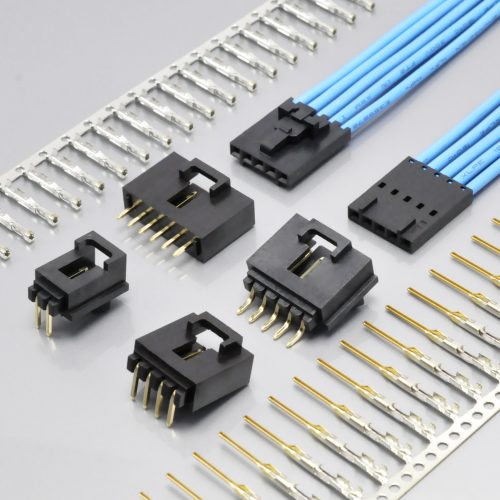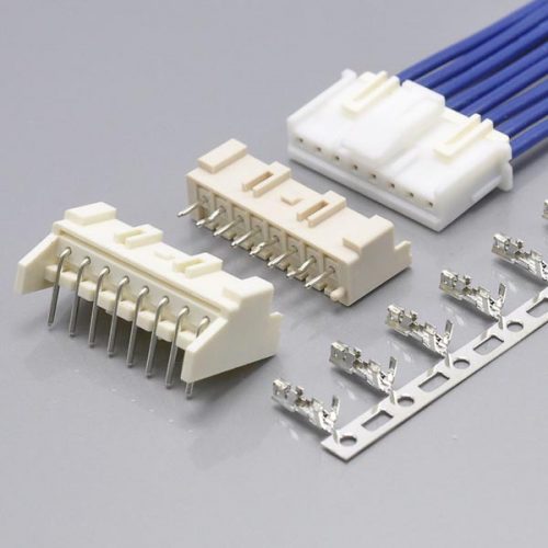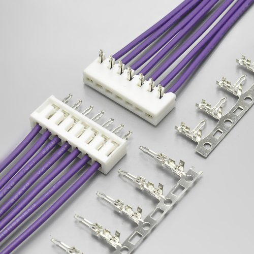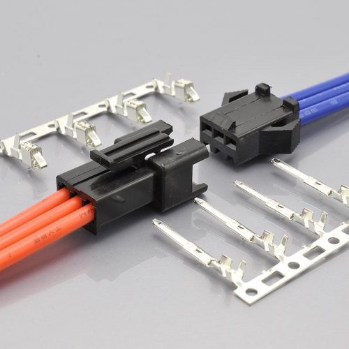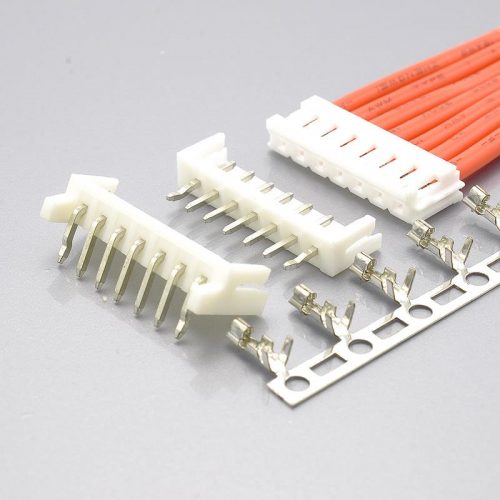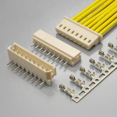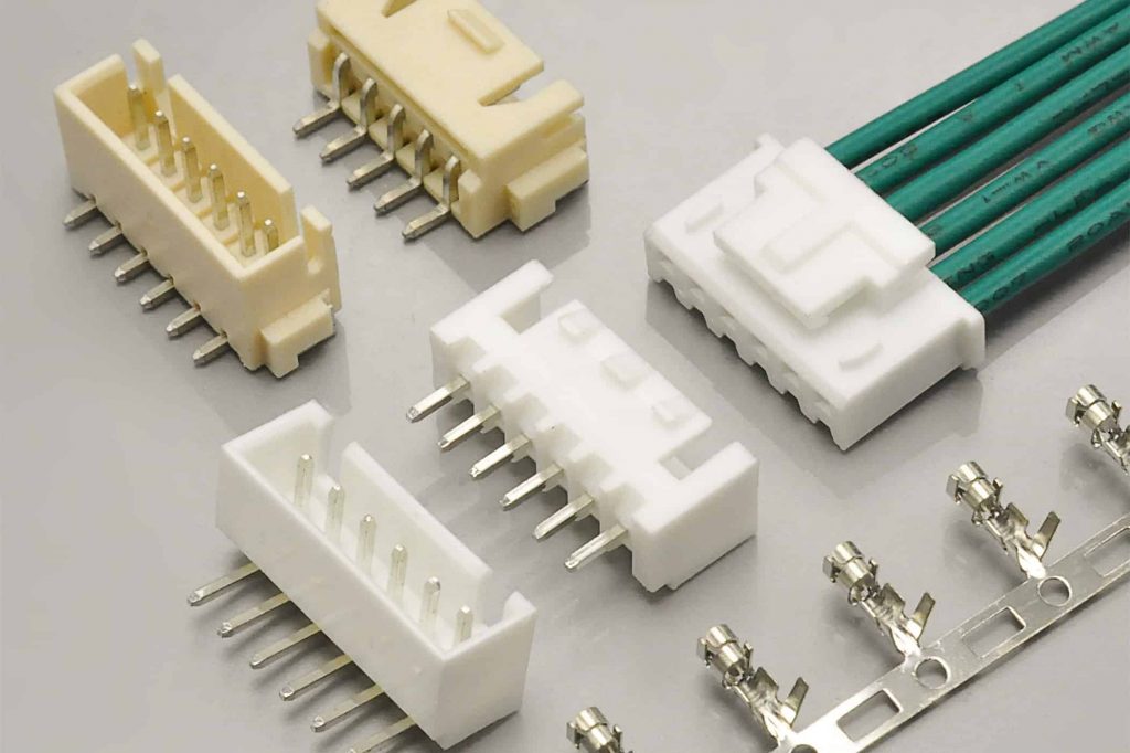
Quick answer: The Yeonho 2.5 connector is a 2.50mm (0.098″) pitch, single-row, crimp wire-to-board system from Yeonho Electronics of Korea, rated 3A and 250V AC/DC, with a 1000MΩ insulation resistance, a 1000V AC / 1 minute withstand on the legacy SMH250 sheets, and an operating range of −25℃ to +85℃. The KONNRA KR2502 is the cross-reference equivalent. Nine of the ratings match, including the wire range of AWG #22 to #28 — but the KR2502 also claims better than the original in four places: a 20mΩ contact resistance against Yeonho’s 30mΩ, 40mΩ after durability against 50mΩ, a crimp strength up to 1.8× higher, and a temperature range 20℃ wider at the hot end. It also claims 2 to 20 circuits where Yeonho catalogues up to 16. Claims that beat the original are the ones to ask for evidence on.
The 2.5mm connector with four part-number families
If you are holding a 2.5mm wire-to-board connector from Yeonho Electronics and cannot find the datasheet, the reason is usually the naming. The same manufacturer’s 2.5mm system is published under several part-number families, and the trade adds a name of its own on top of them.
Yeonho’s own specification sheets carry the description “2.50mm (0.098″) PITCH CONNECTOR” on part numbers in at least these families:
| Family | What the part numbers look like | Role |
|---|---|---|
| SMH250 | SMH250-02 … SMH250-15, SMH250-NN, SMH250-NNL, SMH250-NNI |
The wire-side housing, catalogued as a “Wire-to-Board Housing” |
| SMW250 / SMAW250 / BMW250 | SMW250-NN, SMW250-NND, SMW250-NNIS, SMAW250-NN, SMAW250-NNS5, SMAW250-NNV |
The PCB-side wafer / header — straight and right-angle, through-hole |
| YST025 | YST025, YST025J, YST025L3, YST025-L3 |
The crimp terminal, catalogued as a “Wire-to-Board Crimp Terminal” |
| YH025 / 25045HP / 25048HS / 25045TP / SMP250 / BMH250 | YH025, 25045HP-NNA, SMP250-NN, BMH250-NNS |
Further 2.5mm families — some wire-to-wire, some wire-to-board |
On top of that, the market sells this 2.5mm system under “XHS2.5” — a name that gets searched hard and belongs to no manufacturer’s catalogue. And KONNRA publishes its equivalent as “Yeonho YH 2.5”, which is why the KONNRA page is one of the first places a search for a Yeonho 2.5mm part number lands.
The practical consequence is a one-line rule. At 2.5mm, the pitch identifies nothing and the family name identifies almost nothing either. Quote the full part number — SMH250-04, SMW250-04, YST025 — and match the suffix, because the housing and terminal suffixes are not interchangeable. This guide’s part-number section sets out which goes with which.
One more thing worth knowing before you specify one. Yeonho’s current product menus no longer list the SMH250 housing family — they list SMAW250-NN / -NNS5 / -NNV, SMW250-H12W / -NNIS, SMP250-NN, 25045HP-NNA, BMH250 and others. Yeonho’s own SMH250 and YST025 sheets are still published and still mirrored by the datasheet aggregators, so the part is documented — but SMH250 reads as a legacy designation. If your drawing calls out SMH250-… rather than a current-series part number, ask both your current supplier and us what the current equivalent is before you re-order.
What the Yeonho 2.5mm Wire-to-Board Connector Is
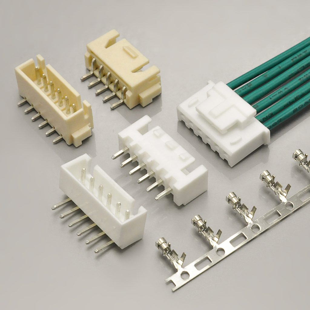
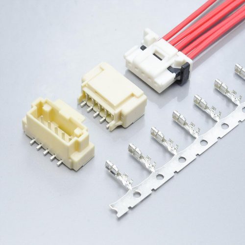
KONNRA KR2502 series YH 2.5 wire-to-board connector with lock, the cross-reference for the Yeonho 2.5mm system
A complete connection is three parts, and Yeonho’s own sheets pair them explicitly:
| Yeonho part | Role | Mates with | Terminal |
|---|---|---|---|
SMH250-NN |
Standard-height wire-side housing | SMW250-NN wafer |
YST025 |
SMH250-NNL |
Low-profile wire-side housing | SMW250-NND wafer |
YST025L3 |
SMH250-NNI |
Height variant (wafer 13.7mm) | SMW250-NNIS wafer |
YST025-L3 |
Read that table as a warning as much as a map. The three housings use three different terminal part numbers, and Yeonho’s own documentation draws the pairing as one-to-one. Mixing a YST025 into an SMH250-NNL housing is not a substitution — it is a different terminal. On the KONNRA side, the KR2502 documents one terminal for the whole series, T25010PT0101F. So when you cross-reference, the question to ask is not “does it mate” but “which housing suffix does your drawing call out, and which terminal does the KR2502 supply against it?”
Yeonho’s sheets describe the connector’s mechanical intent in its own wording:
- “Mis-insertion preventive mechanism” — the housing is polarised so it seats one way only
- “Increase in Crimping Contact Fixation Force” — the retention design is stated in terms of the crimped contact, not the housing latch
- White housing, red retainer — the material table lists
Housing / Plug / RetainerasWhite / White / Red, andRTin a part number such asSMH250J-H04RTis the retainer - Copper alloy pins and terminals, tin plated
Two things Yeonho’s documentation does not state, and which are therefore worth asking for rather than assuming: an applicable wire insulation outside diameter, and a named lock or latch type. Both turn up in this comparison later, and both matter.
The KONNRA KR2502 part numbers
PS-KR2502-01 §2.0 lists six production part numbers for this series. Quote these, not just the series name:
| Component | KONNRA part number |
|---|---|
| Housing | H250201**0101C |
| Terminal | T25010PT0101F |
| DIP right-angle wafer (90°) | C2502RD1**11T0101PA |
| DIP straight wafer (180°) | C2502VD1**11T0101PA |
| SMT right-angle wafer (90°) | C2502RS1**11M01**RA |
| SMT straight wafer (180°) | C2502VS1**11M01**RA |
Note the terminal part number, because this guide returns to it: the KR2502’s terminal and the KR2501’s terminal are the same part number.
Key Specifications at a Glance
| Attribute | Yeonho 2.5mm (manufacturer) | KONNRA KR2502 | Verdict |
|---|---|---|---|
| Pitch | 2.50mm (0.098″) | 2.50mm | Match |
| Current rating | AC/DC 3A | 3A, referenced to 24 AWG | Same number, different reference conductor |
| Voltage rating | AC/DC 250V | 250V AC/DC | Match |
| Withstanding voltage | AC 1000V / 1min (legacy SMH250 and YST025 sheets) | 1000V AC/minute | Match |
| Insulation resistance | 1000MΩ MIN | 1000MΩ Min | Match |
| Contact resistance | 30mΩ MAX | 20mΩ Max | KR2502 claims 33% better |
| Contact resistance after durability | 50mΩ MAX | 40mΩ Max | KR2502 claims 20% better |
| Operating temperature | −25℃ to +85℃ | −40℃ to +105℃ | KR2502 claims 20℃ wider at the hot end, 15℃ at the cold end |
| Applicable wire | AWG #22 to #28 | AWG 22# to 28# | Match |
| Crimp tensile strength | 2.5 / 2.0 / 1.5 / 1.0 kgf MIN (#22 / #24 / #26 / #28) | 4.54 / 3.63 / 2.27 / 1.36 kgf Min | KR2502 claims 1.4× to 1.8× higher |
| Insulation outside diameter | Not published | 1.2mm to 1.8mm | No counterpart to compare |
| Circuits | 2 to 15 on the SMH250 housing sheet; up to 16 on the wafer sheets | 2 to 20 claimed | Conflict — see below |
| Housing material | PA66, UL94 V Grade | PA66 UL94 V-0 (specification §3.0 and housing page) | Match |
| Terminal base metal | Phosphor bronze (YST025 sheet); copper alloy on the current wafer sheets |
Phosphor bronze | Match |
| Plating | Sn | Tin over nickel | Compatible |
| UL file | E108706 | E482542 (KONNRA’s own listing) | Different files, both listed |
| Retainer | Red retainer, RT suffix |
Not documented | KR2502 documents no retainer |
Both columns come from manufacturer documents. Yeonho’s values are read from Yeonho’s own specification sheets, served by yeonho.com or mirrored from Yeonho-authored PDFs by the datasheet aggregators. Sources are listed at the end.
The Four Claims That Beat the Original
This is the section that matters most, and it is the one that runs in the opposite direction from most cross-reference work.
When a second source draws its specification, the safe direction for any disagreement is conservative — a slightly lower current rating, a slightly tighter tolerance, a slightly narrower window. A claim that is better than the original is not automatically wrong, but it is a claim your qualification has to carry, because the original no longer bounds it.
KONNRA’s KR2502 documentation claims better than Yeonho publishes in four places.
1. Contact resistance — 20mΩ against 30mΩ
| Source | Contact resistance |
|---|---|
| Yeonho specification sheets | 30mΩ MAX |
KONNRA PS-KR2502-01 §5.1 |
20mΩ Max |
The KR2502’s documented figure is one third lower than the original’s. KONNRA’s condition is stated precisely — a dry-circuit measurement at 20mV and 100mA maximum, based on EIA-364-23C — and Yeonho’s sheet publishes its own limit under the same test family. A lower contact resistance is a real benefit in a low-level signal application, but the number is KONNRA’s, and the original’s 30mΩ does not support it.
What to ask for: the measured contact-resistance distribution from a production lot, at your wire size, under the dry-circuit condition in §5.1. Not a typical value — a maximum and a sample size.
2. Contact resistance after durability — 40mΩ against 50mΩ
| Source | After the durability test |
|---|---|
| Yeonho specification sheets | 50mΩ MAX |
KONNRA PS-KR2502-01 §7.1 |
40mΩ Max |
The same gap appears after conditioning, and it matters more than the initial figure because this is the number that governs a connector’s behaviour after it has been in service. Yeonho’s durability row allows 50mΩ and Yeonho’s vibration row allows 50mΩ with a 1μsec maximum discontinuity; KONNRA’s §7.1 allows 40mΩ after 30 mating cycles.
The gap is 20%, and it runs the same direction. If your circuit budget assumes 20mΩ initial and 40mΩ end-of-life, the original specification does not guarantee either figure.
3. Crimp strength — up to 1.8× higher
| Wire | Yeonho (manufacturer) | KONNRA (§6.5) | Ratio |
|---|---|---|---|
| 22 AWG | 2.5 kgf MIN | 4.54 kgf Min | 1.82× |
| 24 AWG | 2.0 kgf MIN | 3.63 kgf Min | 1.82× |
| 26 AWG | 1.5 kgf MIN | 2.27 kgf Min | 1.51× |
| 28 AWG | 1.0 kgf MIN | 1.36 kgf Min | 1.36× |
Yeonho publishes a crimp tensile-strength ladder per wire size, and KONNRA publishes one for the same four wire sizes. KONNRA’s is higher at every size — by 82% at the two heavier sizes and 36% at the lightest.
This is the most checkable of the four claims, because crimp tensile strength is a routine pull test and both manufacturers specify it on the same basis. It is also the one an auditor will test first, because a crimp that fails its own stated minimum is a safety issue rather than a performance issue.
What to ask for: the pull-test report at the wire and insulation combination you are actually running, at the four sizes on your drawing.
4. Temperature — 20℃ wider at the hot end
| Source | Operating temperature |
|---|---|
| Yeonho specification sheets | −25℃ ~ +85℃ |
KONNRA PS-KR2502-01 §4.0, and all six component pages |
−40℃ ~ +105℃ |
The KR2502 documents a range 20℃ wider at the hot end and 15℃ wider at the cold end than the original. As with the contact-resistance gap, this is a real capability if it is supported — and the supporting tests do exist in the specification: §7.5 heat resistance at 105 ±2℃ for 96 hours, §7.6 cold resistance at −40 ±2℃ for 96 hours, and §7.8 thermal shock over 5 cycles between −40℃ and +105℃.
But the same house figure appears across the KR2501 and the KR2502 documentation, which is what a house specification looks like rather than a part-specific qualification. If your application sits above +85℃, ask for the heat-ageing report rather than inheriting the range.
A useful cross-check on this one, from the previous series. In the JST XH 2.5 / KR2501 comparison, JST publishes −25℃ to +85℃ and KONNRA publishes −40℃ to +105℃ — the same divergence, against a different original, in the same direction. Two different manufacturers’ datasheets do not agree that this envelope is 20℃ larger; the pattern is KONNRA’s own rating.
The Fifth Claim: 2 to 20 Circuits
KONNRA’s two KR2502 product pages both state “Circuits: 2-20pin”, and the DIP straight wafer component page repeats 2P~20P. Yeonho’s SMH250 housing sheet lists SMH250-02 through SMH250-15 — that is, 2 to 15 circuits — while Yeonho’s wafer sheets run up to 16.
So the 20-position claim goes beyond what Yeonho catalogues, and it is not supported by KONNRA’s own documentation either:
| KONNRA document | Circuit range stated |
|---|---|
| KR2502 product page (both pages) | 2-20pin |
| DIP straight wafer component page | 2P~20P |
| DIP right-angle wafer component page | 2P~18P |
| SMT straight wafer component page | 2P~16P |
| SMT right-angle wafer component page | 2P~16P |
| Housing component page | 2P~16P |
| The specification, §8.0 force table | ends at 16 |
Four different numbers across six pages of one supplier’s own website, and a specification whose force table stops two positions short of the claim on the product page. That is the finding to act on.
What to do about it: if you need more than 16 positions, treat the KR2502 as a 17-to-20-way special and ask for the drawing and the force data for that exact circuit count before you commit a layout. If you need 16 or fewer, the claim is consistent with everything else and the question does not arise.
And one more read of that table. The KR2502’s position on 20 ways is worth understanding in context, because 20 positions is exactly where the JST XH family tops out — JST catalogues the XH at 1 to 16 and 20. A cross-reference that matches the JST ceiling, applied to a Yeonho original that stops at 15 or 16, would produce exactly this overstatement. That is a hypothesis about how the number got there, not a claim about the part — but it is a reason to check the drawing rather than the product page.
Where the Two Documents Agree
The overlap is substantial, and for this pair it includes the one window that most often breaks.
| Attribute | Yeonho | KONNRA | Note |
|---|---|---|---|
| Pitch | 2.50mm (0.098″) | 2.50mm | Dimensionally identical |
| Voltage rating | AC/DC 250V | 250V AC/DC | Rated AC and DC on both sides |
| Current rating | AC/DC 3A | 3A, referenced to 24 AWG | Same number — see the reference-conductor note below |
| Withstanding voltage | AC 1000V / 1min | 1000V AC/minute | Same test, same duration |
| Insulation resistance | 1000MΩ MIN | 1000MΩ Min | Identical |
| Applicable wire | AWG #22 to #28 | AWG 22# to 28# | Identical — the most useful agreement here |
| Housing material | PA66, UL94 V grade | PA66 UL94 V-0 | Same polymer, same class |
| Terminal base metal | Phosphor bronze | Phosphor bronze | Same |
| Plating | Sn | Tin over nickel | Tin finish on both; nickel under-plate on KONNRA’s |
| Row count | Single row | Single row | Same |
| Polarisation | “Mis-insertion preventive mechanism” | “Anti-wrong-insertion design” | Same intent, different wording |
The wire range is the headline agreement, and it is worth saying why. In the JST XH / KR2501 comparison, the replacement’s documented wire range was narrower than the original’s — the KR2501 covers 22#–28# against JST’s #30–#22, so the two finest gauges had no documented home. Here the ranges match exactly: AWG #22 to #28 on both sides. For this cross-reference, a harness already built on 26 or 28 AWG does not need a wire change.
Two caveats sit inside that agreement, though, and both are in Yeonho’s documentation rather than KONNRA’s.
The first is the terminal pairing. Yeonho’s housing and terminal sheets publish AWG #22–#28 as the applicable wire, but Yeonho’s own terminal-to-housing pairing rows are tighter: YST025 against SMH250-NN is listed at AWG #22 ~ #24, and YST025L3 against SMH250-NNL at AWG #22 ~ #24. So the series range and the per-pairing range are not the same statement, and the 26 and 28 AWG rows in KONNRA’s crimp table should be confirmed against the housing suffix your drawing uses.
The second is the reference conductor for the current rating. Both manufacturers publish 3A, and KONNRA’s specification references it to 24 AWG in writing. If your application runs at or near 3A on 22 AWG, ask for the temperature-rise result at that conductor rather than at 24 AWG — the same request the JST XH comparison turned up, and it is the standard question to put to any cross-reference.
The Window That Has No Counterpart
There is one number in KONNRA’s specification that cannot be compared with the original at all, and it is the one that decides whether a harness transfers.
| Source | Applicable wire insulation O.D. |
|---|---|
| Yeonho specification sheets | Not published |
KONNRA PS-KR2502-01 §4.0 |
1.2mm to 1.8mm |
| KONNRA product pages and terminal page | 1.2 to 1.8mm Max |
The insulation outside diameter does not appear on any Yeonho document reviewed for this guide — neither the housing sheet, nor the terminal sheet, nor the current wafer sheets. The YST025 drawing dimensions its metal barrel sections (2.2mm and 1.8/1.6mm) but that is a barrel dimension, not an insulation window.
Two things follow, and both change how you should read KONNRA’s figure.
First, KONNRA’s 1.2–1.8mm is a KONNRA-only number. It cannot be validated by comparison, only by measurement. That is not a defect in the figure — it just means the usual cross-check is unavailable.
Second, it is still the window that fails quietly. An insulation barrel that is too tight for the wire closes on the insulation instead of gripping the conductor; the joint passes a continuity check, ships, and fails in the field. At 2.5mm the insulation barrel has to sit inside the housing cavity, so the insulation diameter is a design input, not a manufacturing detail.
What to do: measure the actual insulation O.D. of the wire on your harness drawing — not the nominal — and confirm it in writing against the terminal you are quoting. Because the original publishes no window, this is the one parameter where you cannot rely on the original datasheet as your safety net.
One Specification, Two Families
Something else about the KR2502 documentation is worth an engineer’s attention, because it explains several of the findings above and it has a direct procurement consequence.
PS-KR2502-01 and PS-KR2501-01 are near-verbatim clones of each other. The two specifications describe two different cross-references — Yeonho 2.5 and JST XH 2.5 — and they are the same document with the part numbers changed:
| Element | PS-KR2501-01 (JST XH) |
PS-KR2502-01 (Yeonho 2.5) |
|---|---|---|
| Document number and edition | PS-KR2501-01, Edition A1 |
PS-KR2502-01, Edition A1 |
| Pages | 7 | 7 |
| Date issued / revised | 2022/2/26 | 2022/2/26 |
| Rated voltage / current | 250V AC/DC, 3A(24AWG) | 250V AC/DC, 3A(24AWG) |
| Rated temperature | −40~+105 | −40~+105 |
| Applicable wire / insulation | AWG 22#~28#, 1.2 to 1.8mm | AWG 22#~28#, 1.2 to 1.8mm |
| Contact / insulation / dielectric | 20mΩ max, 1000MΩ min, 1000V AC 1min | identical |
| §6.1–6.4 mechanical clauses | 1.0 kgf max, 2.0 kgf min pull out, 1.5 kgf min push | identical |
| §6.5 crimp table | 1.75±0.15, 0.73/0.67/0.62/0.55, 1.80/1.70/1.60/1.45, 4.54/3.63/2.27/1.36 | identical |
| §7.1–7.11 environmental programme | 11 tests | identical |
| §8.0 force table | 2 to 16 circuits | identical, including every figure |
| §9.1 / §9.2 solder profiles | 255℃ reflow, 250℃ wave | identical |
| §10.0 remark | “will not be announced in advance” | identical |
| Signatures | Written: Arvin · Checked: / · Approved: Min xinhao | identical |
| Terminal part number | T25010PT0101F |
T25010PT0101F — the same part number |
Two of those rows need to be read carefully.
The shared terminal part number is the one that follows you around. The KR2501 is the cross-reference for the JST XH, and the KR2502 is the cross-reference for the Yeonho 2.5 — two different originals, with two different mating interfaces — and both specifications name the same crimp terminal, T25010PT0101F. That is a statement that one crimp contact serves both housings.
It is not automatically wrong: a manufacturer can design both housings around one terminal, and a common terminal is genuinely convenient if you run both series. But it means the terminal is not what distinguishes these two products, and it means a quotation for “the KR2502 terminal” and “the KR2501 terminal” should come back as the same part. Ask for the terminal drawing and confirm it against the housing cavity for the series you are buying.
The retention clause at section 6.4 is a house-template defect, not a one-off typo. Both specifications require a pin-to-pin retention force of 1.5 kgf (14.7 N) minimum by instructing the operator to “Apply axial push force“. A retention force is the force required to separate two parts, so the test is a pull — and a push in the mating direction is limited by how hard the parts can be pressed together, not by how well they hold. Read literally, neither clause is a retention test.
The content of the clause is right — both documents correctly say “pull out” in the terminal-retention clause immediately above — so this is wording carried across house documents rather than a missing requirement. But it is now confirmed in two series, which means it will appear in others. When you write a test procedure against any KONNRA specification, read §6.4 and write the pull you need rather than transcribing the clause.
What this section is not saying. A shared template is normal in this industry and it is not evidence that the parts are the same. The KR2501 and the KR2502 have different part numbers, different wafer part numbers and different housing part numbers, and the KR2502’s housing page documents PA66 exactly as Yeonho does. The point is narrower and more useful: the specification does not type the two interfaces apart, so the drawing is the document that does.
Where KONNRA’s Own Pages Disagree
The circuit-count conflict is the one that changes a layout. There are others, and they are the reason to read this product off its drawings rather than off its web pages.
Insulation resistance is stated as 100MΩ on one page. The DIP right-angle wafer component page lists Insulation Resistance: 100MΩ Min. Every other KR2502 page — both product pages, the housing page, the terminal page and the three other wafer pages — lists 1000MΩ Min, and the specification §5.2 requires 1000 Megohms Min. A factor-of-ten shortfall on a single page reads as a page-level typing error rather than a product difference, but it is exactly the kind of number a design reviewer will quote, and it should be corrected.
The DIP wafer base material is stated two different ways.
| Document | DIP wafer base |
|---|---|
PS-KR2502-01 §3.0 |
PA9T UL94 V-0 |
| DIP straight wafer page | PA66 UL94 V-0 V-2 |
| DIP right-angle wafer page | PA66 UL94 V-0 V-2 |
| SMT wafer pages | PA9T LCP UL94 V-0 |
Three things are wrong in that table. The specification and the DIP pages name different polymers for the same part — PA9T against PA66. The string “UL94 V-0 V-2” is self-contradictory, because V-0 and V-2 are two different UL 94 ratings and V-2 is the weaker of the two. And the SMT pages name LCP, which the specification allows only as an alternative (“LCP or PA9T” on the KR2501 sheet; simply “PA9T” on this one).
The polymer matters: PA66, PA9T and LCP have different moisture uptake, different reflow tolerance and different cost. For a DIP part, PA66 is the wave-solder choice and PA9T the higher-temperature one.
The compatibility statement is written two ways. The housing page, the terminal page and the DIP straight wafer page each carry Compatible: YH250 Series. The DIP right-angle and both SMT wafer pages carry Compatible: YH Series. One product, two different “compatible” strings — and neither of them is a part number. Since Yeonho’s own catalogue resolves to SMH250, SMW250, SMAW250 and YST025, “YH250 Series” is the string that needs to be reconciled with a real Yeonho part number before it appears on a drawing.
And the KR2502 is published twice. KONNRA has two product pages for this series, at two different URLs:
/product/kr2502-equivalent-to-yeonho-yh2-5-alternatives-connector//product/kr2502-series-yh-2-5-wire-to-board-connector-with-lock/
Both carry the same images, the same General Specification block, the same six components, the same downloads and the same 2-20pin claim. They describe one product twice. That is a duplication to tidy up, and it is the same pattern the KR2501 has — so it is worth checking across the range rather than fixing one page at a time.
One thing this product does get right, and it is worth saying. The KR2502’s General Specification states Withstanding Voltage: 1000V AC/ minute — which matches Yeonho’s own 1000V AC / 1min. The KR2501’s product page states 250V in the same row where its specification says 1000V. The defect did not carry across to the KR2502. The page figure and the specification agree here, which is what makes the 100MΩ line and the 2-20pin claim stand out as exceptions rather than a pattern.
The Mechanical Data in PS-KR2502-01
The specification’s mechanical clauses are short, and reading them carefully pays — one of them was already covered above.
| Clause | What is measured | Test condition | Requirement |
|---|---|---|---|
| §6.1 | Insertion and withdrawal force | At 25.4 ±3mm/minute, excluding plastic detents, EIA-364-13D | Refer to §8.0 |
| §6.2 | Terminal insertion force | Insert the crimped terminal into the housing | 1.0 kgf (9.8 N) max |
| §6.3 | Terminal / housing retention force | Apply axial pull out force at 25.4 ±3mm/minute on the terminal assembled in the housing | 2.0 kgf (19.6 N) min |
| §6.4 | Pin–pin retention force | Apply axial push force at 25.4 ±3mm/minute | 1.5 kgf (14.7 N) min |
§6.3 is the clause to design against, and it is the stronger of the two. A terminal-to-housing retention of 2.0 kgf (19.6 N) minimum means the wire can take a 2kg axial pull before the terminal leaves the housing. Set that against §8.0, where the minimum withdrawal force for the whole 2-circuit connector is 0.60 kgf — which is 0.30 kgf per contact, because that figure is for the complete 2-way assembly and not per position. Put the terminal’s grip inside the housing (2.0 kgf) against the housing’s grip on the header (0.30 kgf per contact) and the ratio is roughly 6.7:1, which is the right direction: a tug on the cable unplugs the connector rather than pulling a terminal out of it.
And do not cross-read §6.2 with §8.0. The 1.0 kgf maximum is the force to click a crimped terminal into its housing cavity, which is a lance-engagement force. The §8.0 figure is the contact-spring force when mating the two halves, and it is larger per contact. They measure different things, and a review that treats the 1.0 kgf cap as the mating limit will conclude the connector fails its own specification.
The insertion and withdrawal force table
PS-KR2502-01 §8.0 gives a per-circuit-count force table in kgf. This is the complete table as published.
| Circuits | Insertion force max | Withdrawal force min, initial | Withdrawal force min, after 30 cycles | Circuits | Insertion force max | Withdrawal force min, initial | Withdrawal force min, after 30 cycles |
|---|---|---|---|---|---|---|---|
| 2 | 3.00 | 0.60 | 0.40 | 10 | 7.00 | 2.20 | 2.00 |
| 3 | 3.50 | 0.80 | 0.60 | 11 | 7.50 | 2.40 | 2.20 |
| 4 | 4.00 | 1.00 | 0.80 | 12 | 8.00 | 2.60 | 2.40 |
| 5 | 4.50 | 1.20 | 1.00 | 13 | 8.50 | 2.80 | 2.60 |
| 6 | 5.00 | 1.40 | 1.20 | 14 | 9.00 | 3.00 | 2.80 |
| 7 | 5.50 | 1.60 | 1.40 | 15 | 9.50 | 3.20 | 3.00 |
| 8 | 6.00 | 1.80 | 1.60 | 16 | 10.00 | 3.40 | 3.20 |
| 9 | 6.50 | 2.00 | 1.80 |
The table is internally consistent to three decimal places, which is the most useful thing that can be said about a force table, because it means the numbers were generated from a model rather than transcribed:
- Insertion force maximum = 2.00 + 0.50 × N kgf — 2 circuits gives 3.00, 16 circuits gives 10.00
- Withdrawal force minimum (initial) = 0.20 + 0.20 × N kgf — 2 circuits gives 0.60, 16 circuits gives 3.40
- Withdrawal force minimum (after 30 cycles) = 0.20 × N kgf — 2 circuits gives 0.40, 16 circuits gives 3.20
All 45 figures in the table reproduce from those three expressions, and every circuit count shows the same 0.20 kgf drop after 30 mating cycles. That is a genuine point in the specification’s favour.
Two practical readings. The insertion force maximum reaches 10.00 kgf — about 98N — at 16 circuits, which is a real number for a hand-assembled harness. And the table stops at 16, which is the evidence behind the circuit-count section above: if the KR2502 is to be supplied at 17 to 20 positions, there is no published force data for it at this edition.
One honest limitation. Yeonho does not publish a series-level insertion and withdrawal force table for this family on the sheets reviewed for this guide, so these figures cannot be reconciled against the original — only checked against themselves, which is what the three expressions above do. If your qualification plan depends on a specific withdrawal force, measure a first article rather than comparing two datasheets drawn on different bases.
Crimp and Termination
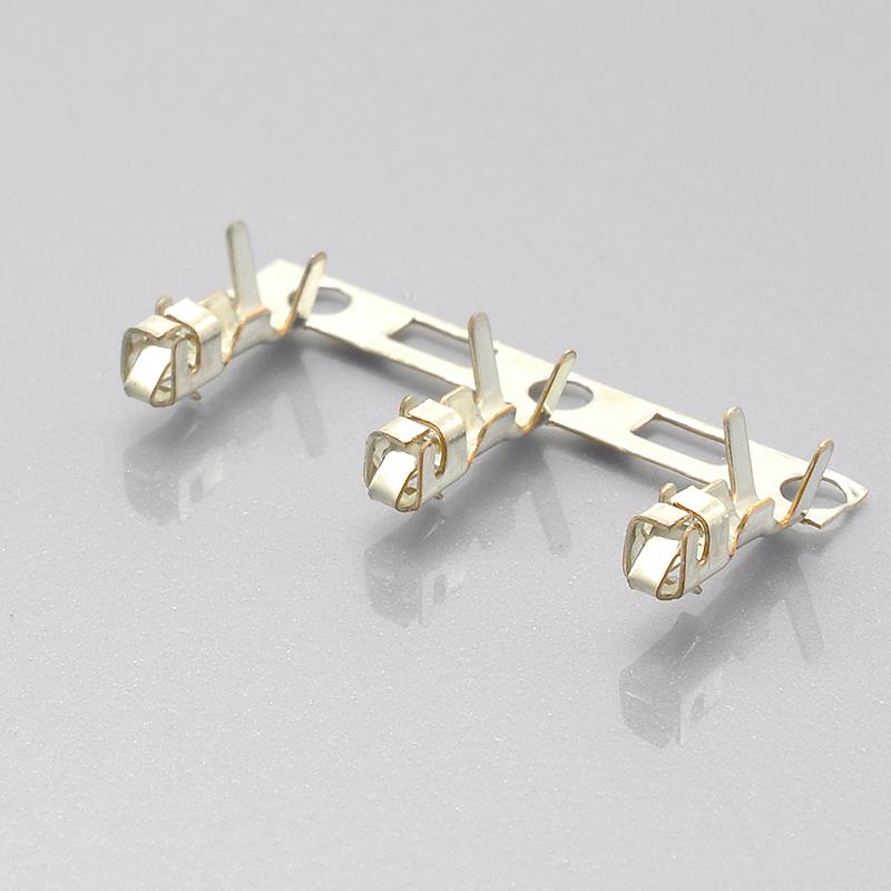
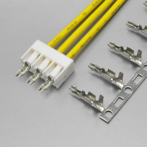
KONNRA KR2502 2.50mm pitch crimp terminal for the Yeonho 2.5 wire-to-board system
PS-KR2502-01 §6.5 publishes a full crimp table. This is more than most cross-reference sources carry, and it is the table a harness shop tooling the connector needs.
| Parameter | 22 AWG | 24 AWG | 26 AWG | 28 AWG |
|---|---|---|---|---|
| Conductor crimp width | 1.75 ±0.15mm (all four sizes) | |||
| Conductor crimp height | 0.73 ±0.05 | 0.67 ±0.05 | 0.62 ±0.05 | 0.55 ±0.05 |
| Insulation crimp width | 2.05mm max (all four sizes) | |||
| Insulation crimp height | 1.80 ±0.10 | 1.70 ±0.10 | 1.60 ±0.10 | 1.45 ±0.10 |
| Crimp strength | 4.54 kgf min | 3.63 kgf min | 2.27 kgf min | 1.36 kgf min |
| Stripping length | 1.6 – 2.1mm (all four sizes) |
Three observations.
The conductor and insulation crimp heights run the right way. Both ladders decrease as the conductor gets thinner — 0.73mm down to 0.55mm for the conductor, 1.80mm down to 1.45mm for the insulation. This is worth checking on any crimp table you are handed, because the direction carries the whole meaning and a reversed ladder is easy to publish and hard to notice.
One number deserves reconciliation before a 22 AWG harness is released. The insulation crimp height at 22 AWG is specified as 1.80 ±0.10mm, so the accepted band runs from 1.70mm to 1.90mm. The top of that band is 0.1mm above the 1.8mm ceiling that section 4.0 of the same specification states for applicable wire insulation. An insulation crimp height is a finished barrel dimension and depends on the wire and the die, so this does not by itself prove a defect — but two numbers in one document that appear not to overlap are worth reconciling in writing rather than discovering at first article.
The crimp strength column is where KONNRA’s documentation beats the original, at every wire size, by the ratios in the table earlier in this guide. That is the single most testable claim in the whole comparison.
And one gap. KONNRA publishes the crimp geometry but no applicator or crimp-machine part numbers. Yeonho’s sheets list a crimp terminal and its tensile strength per wire size but no applicator numbers either — so for this family neither manufacturer publishes the tooling, and if you crimp in house you should ask for the applicator specification with the quote rather than after the first build.
Environmental and Durability Programme
PS-KR2502-01 §7 publishes eleven environmental and durability tests, each with a stated requirement, and the programme is identical to the KR2501’s.
| Clause | Test | Condition | Requirement |
|---|---|---|---|
| §7.1 | Durability | Mated up to 30 cycles at 10 cycles per minute, EIA-364-09C | Contact resistance 40mΩ max |
| §7.2 | Temperature rise | Carrying rated current load, EIA-364-70B | Temperature rise 30℃ max |
| §7.3 | Vibration | Amplitude 1.5mm P-P; sweep 10~55~10 Hz in 1 minute; 2 hours in each X, Y and Z axis, EIA-364-28B | No damage; contact resistance 40mΩ max; discontinuity 1 microsecond max |
| §7.4 | Shock | 490 m/s² (50g), 3 strokes in each X, Y and Z axis, EIA-364-27B | No damage; contact resistance 40mΩ max; discontinuity 1 microsecond max |
| §7.5 | Heat resistance | 105 ±2℃ for 96 hours, EIA-364-17B | No damage; contact resistance 40mΩ max |
| §7.6 | Cold resistance | −40 ±2℃ for 96 hours, EIA-364-59 | No damage; contact resistance 40mΩ max |
| §7.7 | Humidity | 40 ±2℃, 90–95% RH, 96 hours, EIA-364-31B | No damage; contact resistance 40mΩ max; dielectric strength must meet §5.3; insulation resistance 100MΩ min |
| §7.8 | Thermal shock | 5 cycles of −40℃ for 30 min, room temperature 5 min, +105℃ for 30 min, room temperature 5 min, EIA-364-32B | No damage; contact resistance 40mΩ max |
| §7.9 | Salt spray | 16 hours exposure at 35 ±2℃ from a 5 ±1% solution, EIA-364-26B | No damage; contact resistance 40mΩ max |
| §7.10 | Solderability | 3 ±0.5 seconds at 245 ±5℃, EIA-364-52 | 95% of the immersed area must show no voids or pin holes |
| §7.11 | Solder resistance | SMT products per §9.1, EIA-364-56D; DIP products per §9.2, EIA-364-71B | No damage |
The contact-resistance limit jumps after every test, and this is where the comparison bites. Section 5.1 sets 20mΩ max on a dry-circuit measurement. Section 7 then allows 40mΩ max after heat, cold, humidity, thermal shock, salt spray, vibration, shock and 30 mating cycles.
Now put that next to Yeonho’s sheets, which allow 30mΩ max initially and 50mΩ max after durability. KONNRA’s post-conditioning allowance of 40mΩ lands between Yeonho’s initial and post-durability limits — so on the initial figure the KR2502 claims better, and on the post-conditioning figure it claims better too, but by a smaller margin. If your end-of-life budget is set from the original’s 50mΩ, the KR2502’s 40mΩ claim is a tighter guarantee that has to be demonstrated rather than inherited.
Humidity is the only environmental test that tightens the insulation-resistance requirement — §7.7 requires 100MΩ min, against the 1000MΩ min set in §5.2 for a dry part. That is a sensible allowance for absorbed moisture, and it also explains something practical: a nylon-family housing that has absorbed water is the mechanism behind the change in insertion and withdrawal force that shows up on a humid production floor.
Salt spray runs for 16 hours. That is a moderate exposure and it is the test to revisit if the application is outdoor, marine or wash-down.
Durability is specified at 30 mating cycles. Yeonho’s sheets do not publish a mating-cycle count on the documents reviewed here, so the two are not comparable — but 30 cycles is the right order of magnitude for a service connector rather than a production-line one. If your assembly is mated more often — a test fixture, or a field-serviceable module — say so, because that is a change of product class rather than a change of tolerance.
Soldering
PS-KR2502-01 §9 gives two separate temperature profiles, which matters because the KR2502 spans DIP and SMT.
§9.1 — SMT infrared reflow
- Peak temperature: 255 +5/−5℃ held for 5 to 10 seconds
- A 20 to 40 second band at a minimum of 230℃
- A 90 to 120 second reflow band
- Pre-heat: 150 to 200℃
§9.2 — Wave soldering (DIP)
- Peak temperature: 250℃ maximum, held for 3 to 5 seconds
- A 60 to 150 second band at a minimum of 217℃
- A 60 to 180 second total band
- Pre-heat: 150 to 180℃
The specification adds the most honest line in the document: “Please check welding conditions by your own devices beforehand. Because the condition changes by the soldering devices, P.C. boards, and so on.”
Two practical notes. The profiles above are summarised from the specification’s profile drawings, and the drawings carry additional time elements that extracted text does not label unambiguously — take the profile from the drawing, not from this table, when you write your process. And the SMT wafer base is PA9T or LCP per §3.0, which is the reflow-capable choice, while the DIP parts are documented as PA9T and PA66 depending on which page you read. Getting those the wrong way round is a classic way to discover the difference between 255℃ and 260℃ the expensive way.
Documentation and Change Control
PS-KR2502-01 is a 7-page document, Edition A1, carrying the same date in its “Date Issued” and “Date Revised” fields — 2022/2/26 — and no revision history table. Its section 10.0 reads, in full:
“Any change or revision for the product specification will not be announced in advance. Please contact our sales representative for the latest information.”
The signature block reads “Written: Arvin · Checked: / · Approved: Min xinhao”, with the checking field left empty.
The engineering drawing is graphics-only. The KR2502 series drawing is a 2MB PDF whose extractable text content is 12 bytes — everything in it is drawn, not typed. That means no dimension in the series drawing can be found by searching it, and it cannot be diffed against an earlier revision by any automated means.
Against that, here is what the original publishes. Yeonho hosts its own specification sheets as individual PDFs per part number at https://www.yeonho.com/app/product/ca/<PART>.pdf — so there is a document per housing, per wafer and per terminal, each with its measured dimensions and its specification table. The aggregators mirror them, which is how they remain findable even for a family that has left the current menus.
Two practical consequences.
Quote the revision, not just the series. Section 10.0’s wording is a statement that you will not be told when the document changes, which is common in this industry and is exactly the reason to pin what you designed to. If your qualification file cites the KR2502, cite PS-KR2502-01 Edition A1 and the section number, and ask for written confirmation that it is still current at the point you release.
Get the drawing, do not parse it. The KR2502 series drawing is graphics-only and, as set out above, its own web pages disagree with themselves on circuit range, insulation resistance and wafer material. For this product the drawing is the document that settles a question, and the specification is the document that bounds the performance. Ask us for both, for your circuit count and mounting type, and for a 3D model if your CAD system needs one.
The 2.5mm Class: Yeonho, JST XH and the Names in Between
A 2.5mm wire-to-board connector is rarely specified in isolation, so it is worth putting the Yeonho system beside the family it is most often weighed against.
| Attribute | Yeonho 2.5mm (manufacturer) | JST XH |
|---|---|---|
| Pitch | 2.50mm (0.098″) | 2.5mm |
| Current rating | AC/DC 3A | 3A AC/DC (AWG #22) |
| Voltage rating | AC/DC 250V | 250V AC/DC |
| Operating temperature | −25℃ ~ +85℃ | −25℃ to +85℃ |
| Insulation resistance | 1000MΩ MIN | 1,000MΩ min. |
| Withstanding voltage | AC 1000V / 1min | 1,000 VAC for one minute |
| Contact resistance | 30mΩ MAX | Not published on the series page |
| Applicable wire | AWG #22 – #28 | AWG #30 – #22 |
| Insulation outside diameter | Not published | φ0.9mm to φ1.9mm, terminal-dependent |
| Circuits | 2 to 15 (housing sheet); up to 16 on the wafer sheets | 1 to 16, and 20 |
| Mounting | DIP wafers documented; SMT documented | Through-hole and SMT (SMT at 3, 4 and 6 circuits only) |
| Terminal | YST025 / YST025L3 / YST025-L3, matched to the housing suffix |
SXH-001T-P0.6 / -001T-P0.6N / -002T-P0.6 |
| Contact base metal | Phosphor bronze | Phosphor bronze |
| Housing material | PA66, UL94 V grade | PA 6, natural (white) |
| UL file | E108706 | CSA, TÜV, UL listings |
| KONNRA equivalent | KR2502 | KR2501 |
Two things stand out in that table, and both are useful. The two originals publish the same temperature range (−25℃ to +85℃), the same insulation resistance (1000MΩ) and the same withstanding voltage (1000V AC / 1min) — so on the electrical-and-thermal envelope, the Yeonho 2.5 and the JST XH are interchangeable as far as their datasheets go. And they diverge principally on the wire range — Yeonho stops at #22 where JST goes to #30 — which makes the Yeonho pattern the one to choose for heavier wire and the XH the one to choose for fine wire.
Where they do not overlap at all is the pitch class around them. The 2.54mm connectors — Molex KK 254 and the generic “DuPont” header — sit at a different pitch (2.54mm against 2.50mm), which accumulates to 0.6mm across 16 positions. That is the difference between a footprint and a near miss, and it is the single most common reason a 2.5mm design ends up on the wrong board.
And the naming layer on top is thicker at 2.5mm than anywhere else in the connector world. The same Yeonho system answers to SMH250 / SMW250 / SMAW250 / BMW250 / YST025 / YH025 in the manufacturer’s own catalogue and to “XHS2.5” in the trade; KONNRA publishes it as “YH 2.5”; and the connector next to it on the same pitch is JST XH, which is also sold as “XH 2.5” and, wrongly, as “XH 2.54”. Cross-reference on the part number.
➡️ JST XH 2.5 Connector Complete Guide · Yeonho PH 2.0 Connector Complete Guide (KR2004) · Explore the full 2.5mm pitch range
DIP or SMT
| Through-hole (DIP) | Surface mount (SMT) | |
|---|---|---|
| KR2502 components | DIP straight 180°, DIP right-angle 90° | SMT straight 180°, SMT right-angle 90° |
| Documented positions | 20P (straight) and 18P (right-angle) | 16P both |
| Solder profile | 250℃ peak max, 3–5 seconds | 255℃ peak, 5–10 seconds, 230℃ minimum for 20–40 seconds |
| Wafer base material | PA9T per the specification; PA66 per the DIP pages | PA9T or LCP, colour Beige |
| DIP wafer colour | White | — |
| Retention | Pins through the board, load carried by the plating | Solder tab and joint only |
| Best for | Cables that are plugged and unplugged, or pulled on | High-volume assembly where every insertion costs money |
The rule. Choose through-hole when the connector will see repeated mating or cable pull. Choose SMT when assembly cost and board real estate matter more than mechanical retention and the cable will be routed and left alone.
Check the far side of the board. A through-hole header needs clearance behind the PCB. In a stacked design that clearance may not exist, which is the most common reason a 2.5mm design ends up surface mount despite a preference for through-hole.
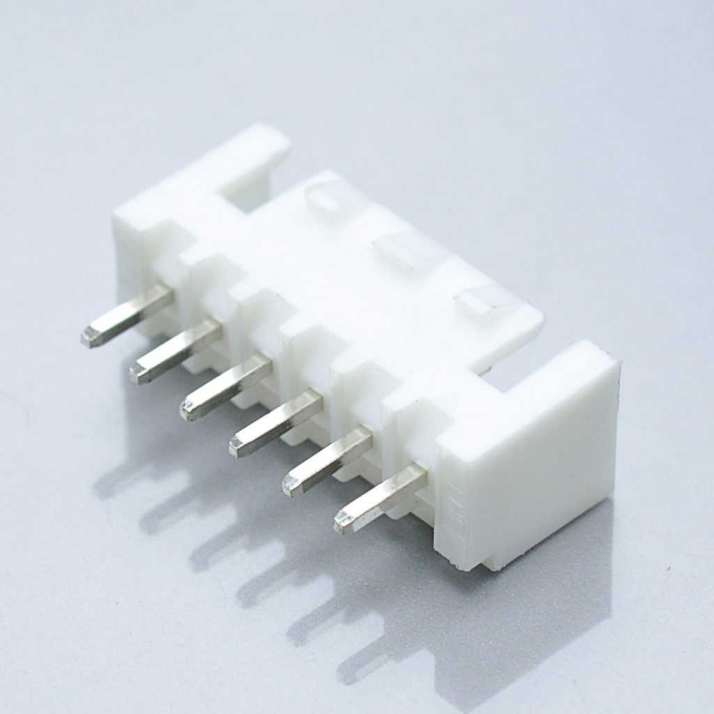
Figure 1 — KONNRA KR2502 DIP straight 180 degree wafer, through-hole top entry
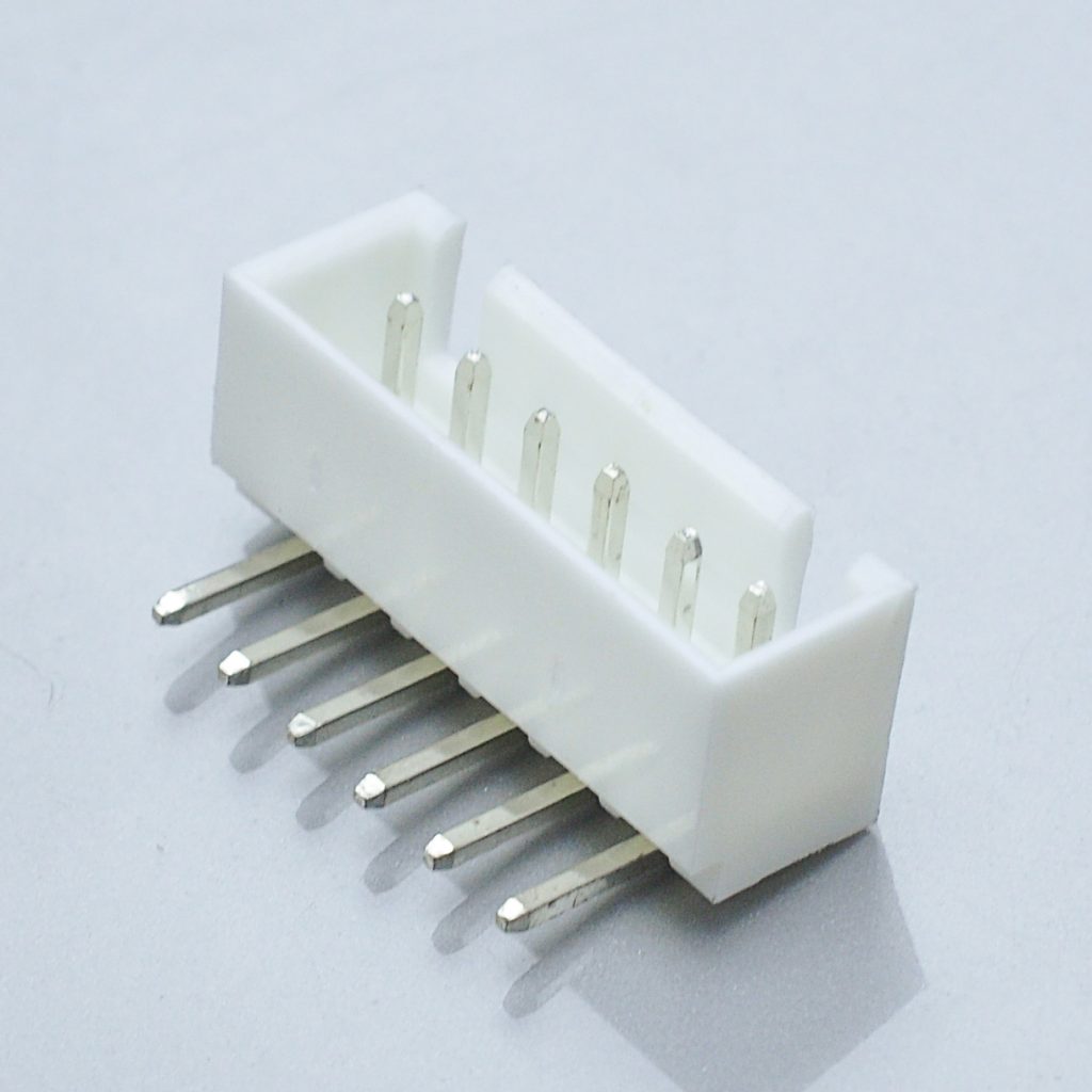
Figure 2 — KONNRA KR2502 DIP right-angle 90 degree wafer
➡️ KR2502 DIP Right Angle Wafer
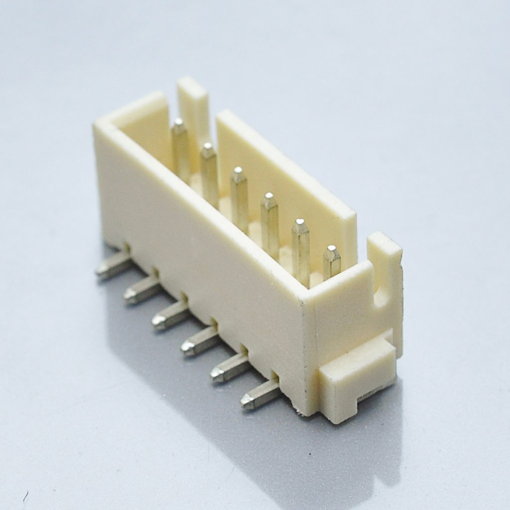
Figure 3 — KONNRA KR2502 SMT straight 180 degree wafer, surface mount
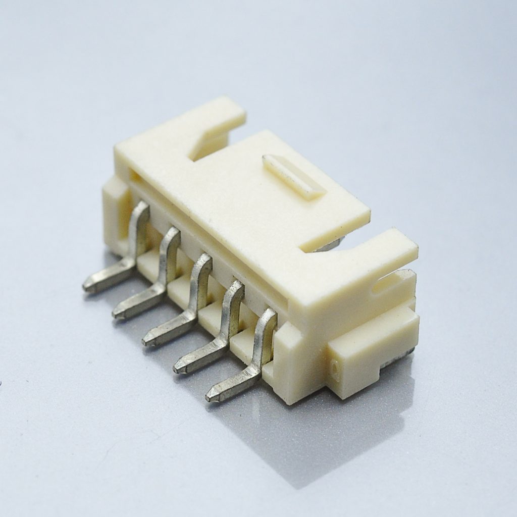
Figure 4 — KONNRA KR2502 SMT right-angle 90 degree wafer, surface mount
➡️ KR2502 SMT Right Angle Wafer
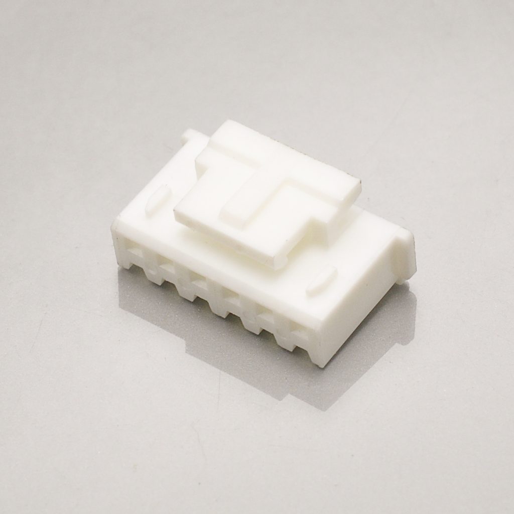
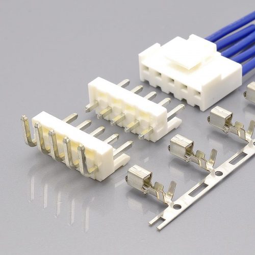
KONNRA KR2502 2.50mm pitch housing, white PA66 UL94 V-0
Full series documentation
- KR2502 series engineering drawing (PDF)
- KR2502 product specification
PS-KR2502-01(PDF) - KR2502 package specification (PDF)
➡️ Request the drawings for your circuit count and mounting type
Applications Where This Pattern Is Used
The Yeonho 2.5 pattern sits where the JST XH sits: bigger than a signal connector, smaller than a power connector.
| Application | Why this pattern fits |
|---|---|
| Home appliances | Control board to module wiring at mains-derived low voltage, with polarisation that survives vibration |
| 3D printer mainboards and hot-end wiring | 2.5mm tolerates repeated mating during maintenance, and 3A covers heater-cartridge and fan loads |
| Industrial control and network equipment | Board-to-module signal and low-power wiring behind a shrouded header |
| Power tools and motor drives | Vibration resistance from the housing and the retainer |
| Automotive accessories and in-vehicle appliances | Interior harnesses where a polarised, retained connection is required |
| Lighting and LED modules | Multi-position power distribution at a pitch that is still hand-serviceable |
| Battery and sensor harnesses | Crimp-terminated, repairable connections at AWG #22 to #28 |
The honest limit is the current. 3A per contact is the ceiling, and above that the answer is a larger pitch rather than a different connector at 2.5mm. And the wire is the other limit: at AWG #22 to #28 the pattern is built for light-to-medium gauge, and a design that needs #30 should be on the JST XH pattern (KR2501) rather than this one.
Cable assembly options
KONNRA builds cable assemblies on the KR2502 system in the standard harness configurations:
| Cable type | Description | Typical use |
|---|---|---|
| Single-headed | Housing on one end, bare wire leads on the other | Pigtail to a wafer, panel wiring |
| Same-side-head | Housing on both ends, same orientation | Board-to-board extension, same-direction routing |
| Reverse-side-head | Housing on both ends, reversed orientation | Board-to-board extension, reversed routing |
| Adapter cables | KR2502 on one end, another series on the other — to JST XH/PH, to 2.54mm DuPont, to JST VH | Interfacing a 2.5mm device to a 2.0mm, 2.5mm or 3.96mm board |
Adapter and transition cables are the most common special requirement at this pitch, and one case sits directly on this product: Yeonho 2.5 to JST XH. Both are 2.50mm, both are 3A/250V, and they do not mate — different housing geometry, different wafer. Where a build has one of each, the fix is an adapter cable rather than a part substitution, and that is a harness to order rather than a connector to swap.
Connector lead time is typically 2–3 weeks; wiring harness lead time is typically 3–4 weeks.
➡️ Explore KONNRA wiring harness capabilities
Sourcing: What Procurement Teams Ask
Engineering decides that a connector will work. Procurement decides whether the supply chain around it is safe — and this family has an unusual provenance problem on top of the usual ones.
“Our drawing says SMH250. Can you supply it?” Yes, and this is worth handling deliberately rather than by part-number match. Yeonho’s own SMH250 sheets remain published, but SMH250 has left Yeonho’s current product menus — so a drawing calling out SMH250-04 may be specifying a legacy designation. Send us the full part number and we will map it to the KR2502 for your circuit count and mounting type, and tell you in writing what differs.
“Can you be a second source without changing our design?” That is what a documented cross-reference is for. The KR2502 is specified against the Yeonho 2.5 system at component level — housing, terminal and four wafers — with a matching 2.50mm pitch, 250V rating and, critically, the same AWG #22–#28 wire range. The four claims in this guide are the caveats: contact resistance, post-durability contact resistance, crimp strength and temperature are all drawn from KONNRA’s own testing and are tighter or higher than the original’s, so we confirm them against your specific part number and wire.
“What are your lead times?” Connector production lead time is typically 2–3 weeks; wiring harness lead time is typically 3–4 weeks. Key materials are prestocked to shorten cycles.
“How long for samples?” Complete connector set samples within 45 days.
“What qualifications do you hold?” KONNRA holds ISO9001, ISO14001, IATF16949, ISO45001:2018 and ISO13485 among its quality systems, together with UL product and operational safety certification — the KR2502 components carry UL file E482542. The Yeonho housing carries its own UL listing, E108706, which is the original’s file rather than ours.
“How do we know the parts match your documentation?” Through a CNAS-accredited laboratory with more than 45 sets of precision testing instruments. Dimensional and electrical verification data are available on request, and where this guide has flagged a difference between two KONNRA documents — the circuit range, the 100MΩ line, the DIP wafer material — the same laboratory can settle it on a first article.
“Are you a manufacturer or a trader?” A manufacturer. Dongguan Konnra Electronics Co., Ltd., founded 2004, with in-house mould design, injection moulding, stamping, assembly and inspection.
How to Get a Cross-Reference Check on Your Part Number
Most 2.5mm sourcing enquiries stall on the same thing: the buyer is not sure which part number to quote, so the enquiry never gets sent. Here is the complete list.
Send us:
- The full Yeonho part number, if you have it —
SMH250-04,SMH250-06L,SMW250-06,SMAW250-NN, or the terminal (YST025,YST025L3,YST025J). Quote the whole string, including the suffix — the housing suffix decides the terminal - Circuit count and row configuration
- Mounting type and entry direction — DIP or SMT, top entry (straight) or side entry (right-angle)
- Wire specification — AWG size and insulation outside diameter measured, not the nominal. Yeonho publishes no insulation window, so this is the one value that has to come from you
- Application and annual volume, so configuration, tooling and packaging can be matched
- A drawing or a photograph, if the part number is unreadable. At 2.5mm a photograph next to a ruler does not separate this family from JST XH, so send the part number if you have it
- Any qualification requirements — automotive, medical, or specific test standards
What you get back: a mapped KONNRA part number with the relevant product and engineering drawings, a specification comparison against your original part including the five claims above, a statement of what the original does not publish so you know which values cannot be validated by comparison, and a sample and quote plan.
Engineer’s Pre-Release Checklist
Run this before you release a drawing for a Yeonho-pattern 2.5mm connector.
- Full part number quoted, including the housing suffix.
SMH250-NNtakesYST025;SMH250-NNLtakesYST025L3. They are not interchangeable. - The “YH250 Series” compatibility string on our pages reconciled to a real Yeonho part number before it appears on your drawing.
- Pitch confirmed by measurement — 2.50mm, not 2.54mm.
- Family confirmed — this system, or JST XH. Both are 2.50mm, 3A and 250V, and they do not mate.
- Insulation outside diameter measured, not assumed, and checked against the 1.2–1.8mm KR2502 window. The original publishes no window, so there is nothing to inherit — this has to be measured.
- Wire size confirmed against the housing pairing, not only the series range, if you are running 26 or 28 AWG.
- Contact-resistance budget set from the original’s 30mΩ / 50mΩ, or from evidence — not from the KR2502’s 20mΩ / 40mΩ claim on its own.
- Crimp strength checked against the original’s 2.5 / 2.0 / 1.5 / 1.0 kgf ladder, and pulled on a first article.
- Temperature requirement checked. Above +85℃, ask for the heat-ageing evidence rather than inheriting −40℃ to +105℃.
- Current requirement checked against the reference conductor. The KR2502 rates 3A at 24 AWG; if you need 3A on 22 AWG, ask for the temperature-rise result at that conductor.
- Circuit count confirmed at the top of the range. Above 16 positions, request the drawing and force data for that exact count — the product page says 20, the SMT pages say 16 and the specification’s force table ends at 16.
- Mounting type decided, and the count inside the range that mounting type documents.
- Wafer base material pinned to one document. The specification says PA9T for DIP; the DIP pages say PA66; the string “UL94 V-0 V-2” appears on both.
- Insulation resistance taken from the specification, 1000MΩ min — and not from the DIP right-angle page, which says 100MΩ.
- Approach to the retention clause in section 6.4 agreed with the supplier, so the test you write matches the test that will be run.
- Crimp applicator data requested with the quote. Neither manufacturer publishes applicator part numbers for this family.
- The drawing requested separately from the specification. The series drawing is graphics-only and the specification does not type this interface against the KR2501.
➡️ Send us your drawing. We will review it against the KR2502 specification and come back with any mismatch we find — before you commit tooling. Submit a drawing for review
Frequently Asked Questions
What is a Yeonho YH 2.5 connector?
A 2.50mm (0.098″) pitch, single-row, crimp wire-to-board connector system from Yeonho Electronics of Korea, rated 3A and 250V AC/DC, with 1000MΩ insulation resistance, a 1000V AC / 1 minute withstand on the legacy SMH250 and YST025 sheets, an operating range of −25℃ to +85℃, and an applicable wire range of AWG #22 to #28. A complete connection is a wire-side housing, a PCB-side wafer and a crimp terminal.
Is the Yeonho YH 2.5 the same as SMH250?
They are the same 2.5mm pitch system published under different part-number families. Yeonho’s own specification sheets carry the description “2.50mm (0.098″) PITCH CONNECTOR” for SMH250 (the wire-side housing, catalogued as a “Wire-to-Board Housing”), SMW250 / SMAW250 / BMW250 (the PCB wafers), YST025 (the crimp terminal), and also for YH025. The trade additionally sells this system as “XHS2.5”. Because the naming is layered, quote the full part number — SMH250-04, SMW250-04, YST025 — and match the suffix, since the housing and terminal suffixes pair one-to-one.
What is the KONNRA equivalent of the Yeonho 2.5 connector?
The KONNRA KR2502 series — a 2.50mm pitch single-row wire-to-board connector offered as DIP straight 180°, DIP right-angle 90°, SMT straight 180° and SMT right-angle 90° wafers, plus a housing and a crimp terminal. Housing H250201**0101C, terminal T25010PT0101F, and four wafer part numbers. Nine ratings match the original — including the AWG #22–#28 wire range — and four claims are tighter or higher (see below).
What is the XHS2.5 connector?
“XHS2.5” is a market name, not a manufacturer’s series. It is used in the trade for the Yeonho 2.5mm pitch wire-to-board system — the same family catalogued by Yeonho as SMH250 (housing), SMW250 / SMAW250 (wafers) and YST025 (terminal). Searching it also returns JST XH connectors mislabelled as XHS, which is why it costs time. If your BOM says XHS2.5, quote the underlying Yeonho part number when you enquire.
Is the Yeonho 2.5 connector compatible with JST XH?
No — and they look identical on paper. Both are 2.50mm pitch, both are 3A and 250V AC/DC, both publish −25℃ to +85℃ and 1000MΩ and 1000V AC / 1min. They differ in housing geometry and mating interface, and they do not mate. They also differ in wire range: Yeonho accepts AWG #22–#28 against JST’s AWG #30–#22. The KONNRA equivalents are KR2502 for the Yeonho pattern and KR2501 for the JST XH pattern. Where a build needs both, the answer is an adapter cable rather than a substitution.
Which Yeonho terminal goes with which housing?
Yeonho’s own sheets pair them one-to-one, and the suffixes are not interchangeable:
| Housing | Wafer | Terminal |
|---|---|---|
SMH250-NN (standard height) |
SMW250-NN |
YST025 |
SMH250-NNL (low profile) |
SMW250-NND |
YST025L3 |
SMH250-NNI |
SMW250-NNIS |
YST025-L3 |
KONNRA documents one terminal for the whole KR2502 series. So the question to put to a supplier is not “does it mate” but which housing suffix your drawing calls out, and which terminal is quoted against it.
What wire gauge does the Yeonho 2.5 connector use?
AWG #22 to #28 on Yeonho’s housing and terminal specification sheets. Two cautions. First, Yeonho’s terminal-to-housing pairing rows are tighter — YST025 with SMH250-NN and YST025L3 with SMH250-NNL are each listed at AWG #22 ~ #24 — so the series range and the per-pairing range are not the same statement. Second, Yeonho publishes no applicable insulation outside diameter, so the insulation window has to be measured rather than looked up. KONNRA documents 1.2mm to 1.8mm for the KR2502, which is our own figure and has no counterpart in the original.
What is the contact resistance of the Yeonho 2.5 connector?
30mΩ MAX on Yeonho’s specification sheets, with 50mΩ MAX after the durability test. KONNRA’s KR2502 documents 20mΩ Max initially (§5.1, dry circuit at 20mV and 100mA maximum, EIA-364-23C) and 40mΩ Max after 30 mating cycles (§7.1). Our figures are better than the original’s — 33% lower initially and 20% lower after conditioning — which means they are our claims and should be evidenced with lot data rather than inherited from the original.
What is the operating temperature range?
Yeonho’s sheets publish −25℃ to +85℃. KONNRA documents the KR2502 at −40℃ to +105℃ — 20℃ wider at the hot end and 15℃ wider at the cold end. The supporting tests are in the specification: heat resistance at 105±2℃ for 96 hours (§7.5), cold resistance at −40±2℃ for 96 hours (§7.6) and thermal shock over 5 cycles between −40℃ and +105℃ (§7.8). If your application runs above +85℃, ask for the heat-ageing report.
How many circuits does the Yeonho 2.5 connector come in?
Yeonho’s SMH250 housing sheet lists 2 to 15 circuits (SMH250-02 through SMH250-15), and the wafer sheets run up to 16. KONNRA’s product pages claim 2 to 20, but our own pages do not agree with each other — 20P on the straight DIP wafer, 18P on the right-angle DIP wafer, 16P on both SMT wafers and the housing page — and the specification’s force table stops at 16. Above 16 positions, request the drawing and force data for that exact circuit count.
Does the connector have a surface-mount version?
KONNRA documents the KR2502 with SMT straight 180° and SMT right-angle 90° wafers, both documented to 16 positions, in Beige with a PA9T or LCP base. The SMT profile is 255 +5/−5℃ peak for 5 to 10 seconds, with a 20–40 second band at a minimum of 230℃ and a 90–120 second reflow band.
What is the withstanding voltage and insulation resistance?
Withstanding voltage: 1000V AC for 1 minute on Yeonho’s legacy SMH250 and YST025 sheets — Yeonho’s newer wafer sheets publish the pass criterion (“no flash over and no physical damage”) without a numeric value. Insulation resistance: 1000MΩ MIN. The KONNRA KR2502 specification §5.3 states the same 1000V AC for 1 minute (EIA-364-20A) and §5.2 the same 1000MΩ min — and, unlike the KR2501’s page, the KR2502 product page states 1000V AC/minute correctly. One KR2502 component page states 100MΩ instead of 1000MΩ; the specification is the controlling document.
What is the difference between the Yeonho 2.5 and the JST XH?
Very little on paper, and everything in the mating interface. Both are 2.50mm pitch, 3A, 250V AC/DC, both publish −25℃ to +85℃, 1000MΩ and 1000V AC / 1min, and both use a phosphor bronze terminal with tin plating. They diverge on the wire range — Yeonho #22–#28 against JST #30–#22 — on circuit counts — Yeonho 2–15/16 against JST 1–16 and 20 — and on the housing and wafer geometry, which means they do not mate and do not share a footprint. Choose the Yeonho pattern for heavier wire and the XH pattern for fine wire.
How do I identify which 2.5mm connector I actually have?
Measure the centre-to-centre distance between adjacent contacts — 2.50mm is this class, 2.54mm is Molex KK / “DuPont”, 2.00mm is JST PH, 1.5mm is ZH. Then measure the housing across the contact field, which for a 2.50mm single row is (N − 1) × 2.5mm, so a 4-way measures 7.5mm. Because this system and the JST XH sit at the same pitch with the same electrical ratings, the pitch does not separate them — the part number, the housing profile and the wafer do. If the part number is unreadable, photograph the connector next to a ruler and send it to us.
How long does it take to get samples?
KONNRA can deliver complete connector set samples within 45 days. Connector production lead time is typically 2–3 weeks and wiring harness lead time typically 3–4 weeks.
Start Your Cross-Reference Check
KONNRA supplies the KR2502 series as individual components or as complete pre-crimped cable assemblies, in DIP and SMT configurations, with customisation available for application-specific requirements.
- Request a quote — KR2502 pricing, MOQ and configuration options for your circuit count and mounting type
- Request a sample — complete connector set samples within 45 days
- Request cross-reference verification — confirm KR2502-to-Yeonho equivalence against your specific part number, including the wire and insulation windows
- Request the performance evidence — contact-resistance lot data, crimp pull tests and heat-ageing reports behind the four claims in this guide
- Request drawings — series engineering drawing, product specification and package specification
- Request the crimp applicator data — if you crimp in house
- Request a vendor qualification pack — certificates, test capability summary and quality documentation
- Request adapter and transition cable assemblies — Yeonho 2.5 to JST XH, to JST PH, to 2.54mm DuPont
- Submit a drawing for review — we will flag any specification mismatch before you commit tooling
Contact KONNRA Electronics
- Phone: (86)-769-85449875
- Email: info@konnra.com
- Address: No.6 Nanchang South Road, Chijiao, Wangniudun, Dongguan, Guangdong, China
- Contact us
Sources and method. Every figure in this guide is taken from a manufacturer document, and where two manufacturers — or two documents from the same manufacturer — disagree, the difference is stated rather than averaged. Yeonho figures are read from Yeonho Electronics’ own specification sheets, either served by yeonho.com (the PDFs at https://www.yeonho.com/app/product/ca/<PART>.pdf) or from the identical Yeonho-authored PDFs as mirrored by the datasheet aggregators: the SMH250 housing sheet and the YST025 terminal sheet for the legacy values (housing material PA66 UL94 V grade, UL file E108706, contact resistance 30mΩ MAX, durability and vibration 50mΩ MAX with 1μsec maximum discontinuity, insulation resistance 1000MΩ MIN, withstanding AC 1000V / 1min, applicable wire AWG #22–#28, operating temperature −25℃ ~ +85℃, the crimp tensile ladder 2.5 / 2.0 / 1.5 / 1.0 kgf MIN, and the available-pin table SMH250-02 to SMH250-15), and the current wafer sheets (SMW250-NNIS, SMAW250-NN, SMP250-NN, 25045HP-NNA) for the terminal-to-housing pairing rows, the series role names, pin ranges up to 16, and the currently published ratings (AC/DC 3A, AC/DC 250V, PA-series resin and the white/white/red colour scheme). JST XH figures in the 2.5mm class comparison are from JST’s published XH series page and XH catalogue, as set out in full in the JST XH 2.5 guide linked above. KONNRA KR2502 figures are from PS-KR2502-01 (Edition A1, dated 2022/2/26, 7 pages) sections 2.0, 3.0, 4.0, 5.1–5.3, 6.1–6.5, 7.1–7.11, 8.0, 9.0 and 10.0, and from the two KR2502 product pages and the six KR2502 component pages. Three limitations are stated openly. First, Yeonho publishes no applicable wire insulation outside diameter for this family, so the KR2502’s 1.2–1.8mm window could not be reconciled against the original — it has to be validated by measurement and by our drawing. Second, Yeonho does not name a lock or latch type in the documents reviewed, and does not state whether the housing is shrouded, so this guide does not claim a named retention mechanism for either side. Third, the numeric withstanding-voltage value and its 1-minute duration appear on Yeonho’s legacy SMH250 and YST025 sheets; Yeonho’s currently published wafer sheets give only the pass criterion, so the 1000V AC / 1min agreement is stated against the documents that carry the number. Where a figure here disagrees with the current revision of a manufacturer document, the manufacturer document is right.