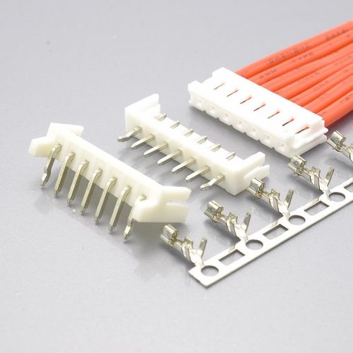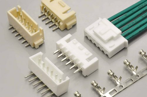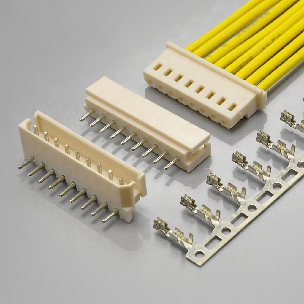
Quick answer: Molex’s Mini-SPOX is a 2.50mm pitch, single-row, wire-to-board system rated 250V and 3.0A maximum per contact, in 2 to 15 circuits, with a wire range of AWG #22 to #28 and an insulation window of φ1.15mm to φ1.9mm. The KONNRA KR2500 is the cross-reference offered for it, and all four of its cross-referenced part families check out against Molex’s own catalogue: the friction-lock receptacle housing is 5264, the female crimp terminal is 5263, the vertical plug is 5267 and the right-angle plug is 5268.
That is worth saying plainly, because it is not the usual finding on this catalogue. Three things then decide whether the swap works, and each is visible in the two manufacturers’ published documents.
The first: the insulation window is the one number to check before anything else. Molex specifies applicable wire insulation of φ1.15mm to φ1.9mm. KONNRA’s specification gives 1.6mm maximum, and its web pages publish only that ceiling. A 22 AWG wire with 1.8mm insulation sits inside Molex’s specified window and outside KONNRA’s. Section 2 sets out the arithmetic and what to do about it.
The second: the circuit count in KONNRA’s tables is 16, and the original ends at 15. KONNRA’s product page and all four component pages say 2P~16P, and the specification’s force table runs from 2 to 16. Molex’s Mini-SPOX is a 2 to 15 circuit system — that is the figure on Molex’s own family page, in the 20-sheet product specification, and in the housing range. Oddly, KONNRA’s own Overview paragraph says “2 to 15 circuits” as well. Section 3 explains which document is which.
The third: on the measurements that decide a connector’s mechanical worth, the cross-reference is stronger than the original, and the numbers are checkable. Terminal retention is specified at 2.0 kgf minimum against Molex’s 1.5 kgf; header pin retention at 1.5 kgf against 1.0 kgf; crimp pull-out strength is higher at all four wire gauges. And the withdrawal-force ladder is numerically identical to Molex’s for 2 through 7 circuits, which is the strongest evidence available that the two parts are mechanically the same interface. Sections 4 and 5.
One naming note before the tables. Mini-SPOX is a system, not a single part, and Molex splits it across four series numbers: 5267 (plug assembly, vertical), 5268 (plug assembly, right-angle), 5264 (receptacle crimp housing) and 5263 (receptacle crimp terminal). KONNRA calls the two board-side parts wafers — a straight wafer and a right-angle wafer. If you arrived here holding a Molex part number, find it in section 11 first; the four series use different ratings tables in Molex’s own catalogue, and the housing and terminal carry figures the plug does not.
Everything below is taken from Molex’s Mini-SPOX family page, its 20-sheet product specification PS-5264-001 (Revision J), its series charts for 5263, 5264, 5267 and 5268, and its part page for 22035025 — and from KONNRA’s PS-KR2500-01 (Edition A1) together with the KR2500 product page and its four component pages. All are listed at the end.
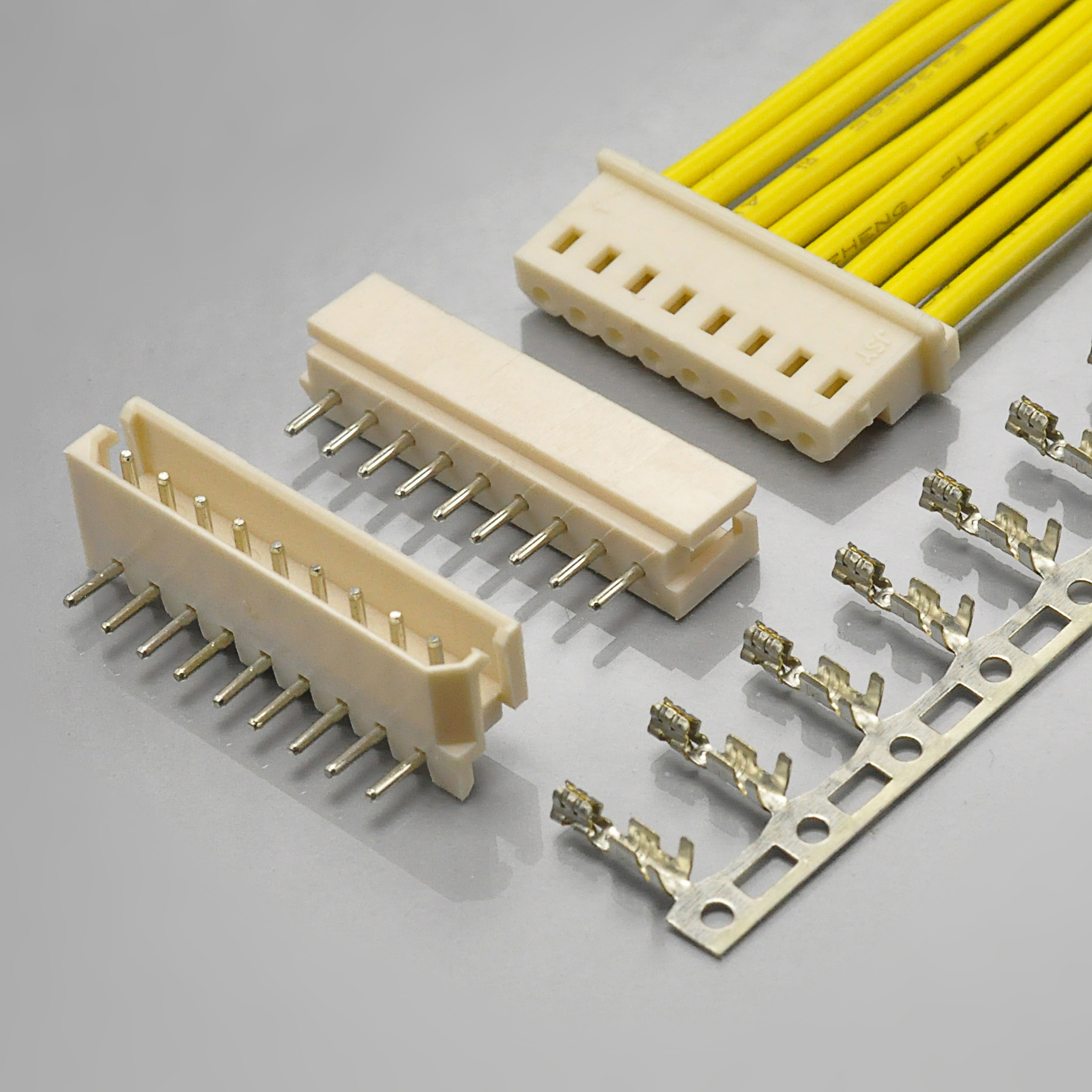
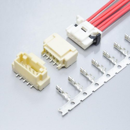
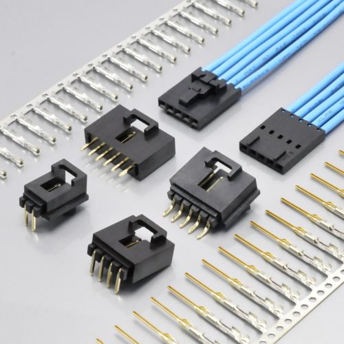
KONNRA KR2500 series Mini-SPOX 2.50mm wire-to-board connector, the cross-reference offered for the Molex Mini-SPOX system
At a glance
| Item | Molex Mini-SPOX, catalogue | Molex PS-5264-001 product spec |
KONNRA KR2500 |
|---|---|---|---|
| System | 2.50mm pitch, single row, wire-to-board, through-hole | same | Wire to Board, DIP only |
| Series numbers | 5267 vertical plug · 5268 right-angle plug · 5264 housing · 5263 terminal | all four listed in §2.0 | one set: two wafers, one housing, one terminal |
| KONNRA cross-reference | — | — | straight wafer ↔ 5267 · right-angle wafer ↔ 5268 · housing ↔ 5264 · terminal ↔ 5263 |
| Circuits | 2 – 15 (family page). 5267 vertical: 2–12, 14, 15 in the 22035**5 family and 2–13 in the 999909** family. 5268 right-angle and 5264 housing: 2–15 continuous |
force table covers 2 – 15 | 2-16pin (product page) · 2P~16P (all four component pages) · 2 – 16 (spec force table) · 2 to 15 (product page Overview prose) |
| Rated voltage | 250V | 250V AC (rms) / DC | 250V AC/DC |
| Current | 3.0A max per contact · family page quotes 4.0A max derating current | 3.0A at AWG#22, 2.5A at #24, 2.0A at #26, 1.5A at #28 — and a derating table giving 4.0A at 2 circuits / 3.5A at 8 / 3.0A at 15 for 22 AWG | 3A (22AWG) — a single figure, no circuit-count or gauge derating |
| Operating temperature | −55° to +105°C | −55°C ~ +105°C, not to freeze at low temperature | −40°C to +105°C |
| Applicable wire | AWG 22, 24, 26, 28 | AWG #22 – #28 | AWG 22# – 28# |
| Wire insulation O.D. | 1.90mm max (terminal page) | φ1.15mm ~ φ1.9mm | 1.6mm (Max.) — no floor published on any page |
| Contact resistance | — | 20mΩ max (dry circuit 20mV max, 10mA max) | 20mΩ max (dry circuit 20mV max, 100mA max) |
| Crimp-portion contact resistance | — | 5mΩ max | not published |
| Insulation resistance | — | 1,000MΩ min at 500V DC | 1,000MΩ min at 500V DC |
| Dielectric strength | — | 1,000V AC (rms) for 1 minute | 1,000V AC for 1 minute |
| Durability | 30 mating cycles max | 30 cycles at ≤10 cycles/minute | 30 cycles at ≤10 cycles/minute |
| Terminal insertion force | — | 1.5 kgf (14.7N) max | 1.0 kgf (9.8N) max |
| Terminal retention force | — | 1.5 kgf (14.7N) min | 2.0 kgf (19.6N) min |
| Header pin retention | — | 1.0 kgf (9.8N) min | 1.5 kgf (14.7N) min |
| Crimp pull-out strength, min | — | 22 AWG 4.0 kgf · 24 AWG 3.0 kgf · 26 AWG 2.0 kgf · 28 AWG 1.0 kgf | 22 AWG 4.54 kgf · 24 AWG 3.63 kgf · 26 AWG 2.27 kgf · 28 AWG 1.36 kgf |
| Lock and polarisation | Friction lock; polarized to mating part Yes; keying to mating part No; shrouded | friction lock | friction-lock design; non-rectangular housing for mating orientation |
| Housing resin | Nylon, natural, 94V-0 | high heat resistant polyamide | PA66 UL94 V-0, beige |
| Terminal material and plating | Phosphor bronze, tin · plating min 0.889µm mating / 0.914µm termination | tin | Phosphor bronze, tin over nickel · thickness not published |
| Plug plating | Tin, plating min 4.064µm | tin | Brass contact, tin over nickel · thickness not published |
| PCB thickness | 1.60mm recommended | — | not published |
| PC tail length | 3.50mm | — | not published |
| Agency | UL E29179, CSA LR19980 | — | UL E482542 |
| Environmental tests | — | 13 items (§4-3-1 to §4-3-13) | 11 items (§7.1 to §7.11) |
| Application notes | — | 31 numbered notes (§7.0) | none — a single remark in §10.0 |
| Document control | part-level change notifications published | Revision J, 2020/05/08; revision history back to 1988/06/21 | Edition A1, 2022/02/26; no revision history |
Four rows in that table carry the whole comparison.
The insulation row is the one that will stop a build. It is the only parameter in the table where the replacement’s published window is narrower than the original’s in a way that excludes a wire the original rates. Section 2.
The circuit row contains the only figure in KONNRA’s documentation that the original cannot match. Section 3.
The three force rows run the other way — retention up, insertion down — and they are the strongest part of the case for the KR2500. Section 5.
The last three rows are about documentation rather than hardware, and they are worth reading if you are filing this cross-reference in a qualification pack. Section 10.
1. The cross-reference checks out — all four part families
This is the finding to read first, because it decides whether the rest of the article applies to you at all. On most cross-references in this catalogue at least one part number turns out to point at the wrong series. On this one, all four point at the right place, and that is verifiable against Molex’s own documents in about five minutes.
| KONNRA part | KONNRA states Compatible |
Molex’s own name for that series | Molex’s own part-number pattern |
|---|---|---|---|
Straight wafer (2500-dip180) |
5267 Series | Plug Assembly (Vertical type) — PS-5264-001 §2.0, drawing 52670001-SD |
22035**5, and 999909** for the vertical type with swaged tails |
Right-angle wafer (2500-dip90) |
5268 Series | Plug Assembly (Right angle type) — PS-5264-001 §2.0, drawing 52680001-SD |
22057**5 |
Housing (2500-h) |
5264 Series | Receptacle Housing — PS-5264-001 §2.0, drawing 52640001-SD |
50375**3 |
Terminal (2500-t) |
5263 Series | Receptacle Crimp Terminal — PS-5264-001 §2.0, drawing 52630001-SD |
087010** |
Every one of those four is confirmed twice over on Molex’s side. The product specification lists the four series numbers against the four part-number patterns, and the part page for 22035025 — a 2-circuit vertical plug — carries the line Mates With: Mini-SPOX Single Row Receptacle Housings, 5264, which is the same pairing KONNRA’s housing page states independently.
Three further agreements are worth recording, because they are the ones a designer will look for first:
- The friction lock is real and is named on both sides. Molex’s family page lists “Friction lock: Provides better mating retention of housing and header”, and the
5268right-angle series description reads “…Through Hole, Tin Plating, Friction Lock, 2 Circuits…”. KONNRA’s product page opens with “with its unique friction-lock design, ensures that mating is securely fastened”. Same feature, same word. - The polarisation feature is real. Molex lists
Polarized to Mating Part: YesandKeying to Mating Part: Noand describes “the unique non-rectangular housing shape”. KONNRA describes “the non-rectangular housing shape of the KR2500 series connectors has been cleverly designed to solve this problem and ensure accurate mating orientation”. Note the distinction Molex draws: the housing polarises, but there is no keying — so orientation is protected while insert-in-the-wrong-header is not. Worth knowing before you design a family of similar harnesses. - The wire gauge range matches exactly. Molex’s terminal series 5263 covers
22, 24, 26, 28AWG; KONNRA publishes22#-28#and its crimp table has a row for each of the four. That alignment is what makes the crimp comparison in section 5 possible at all.
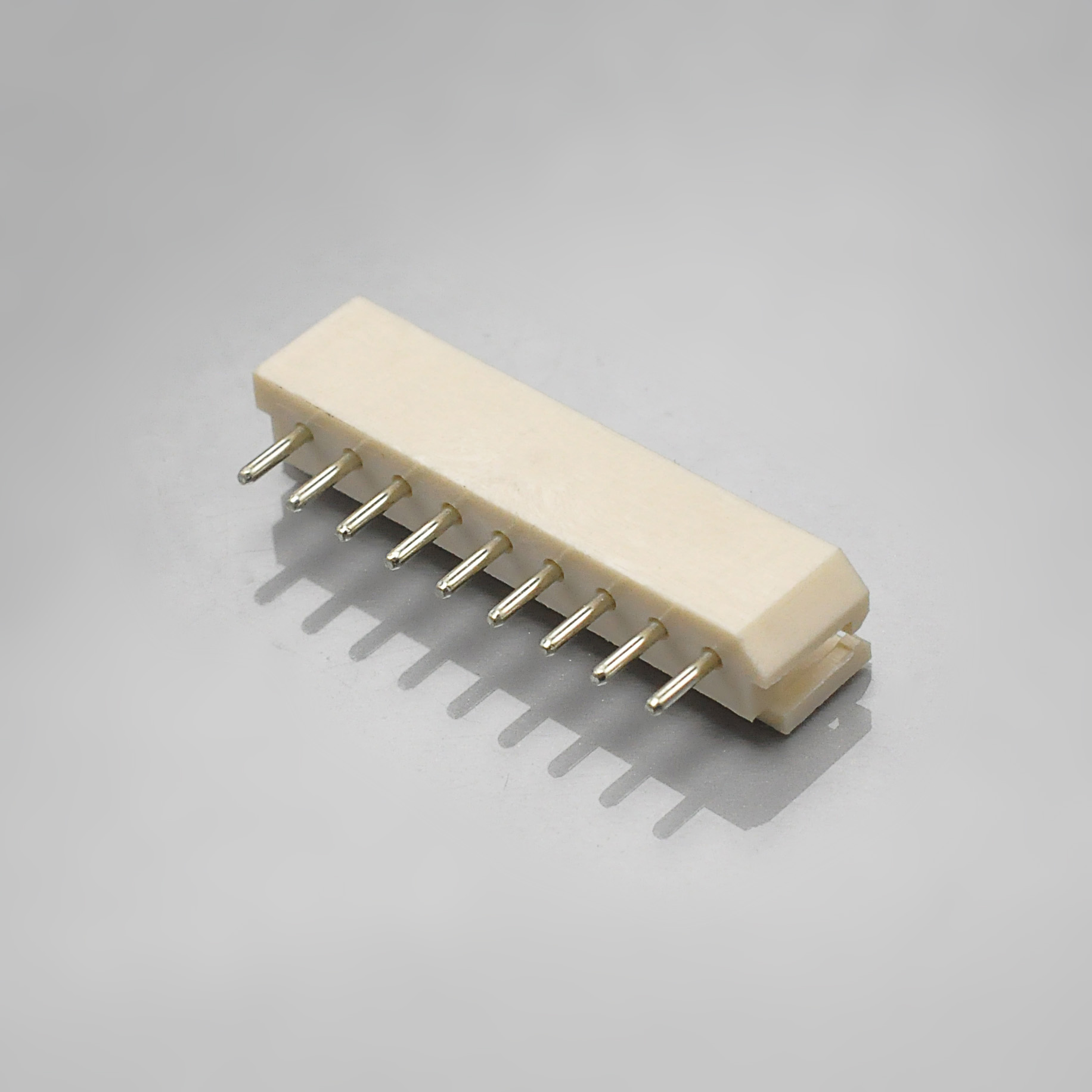
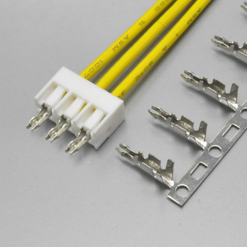
KONNRA KR2500 straight DIP type wafer, cross-referenced to Molex Mini-SPOX series 5267
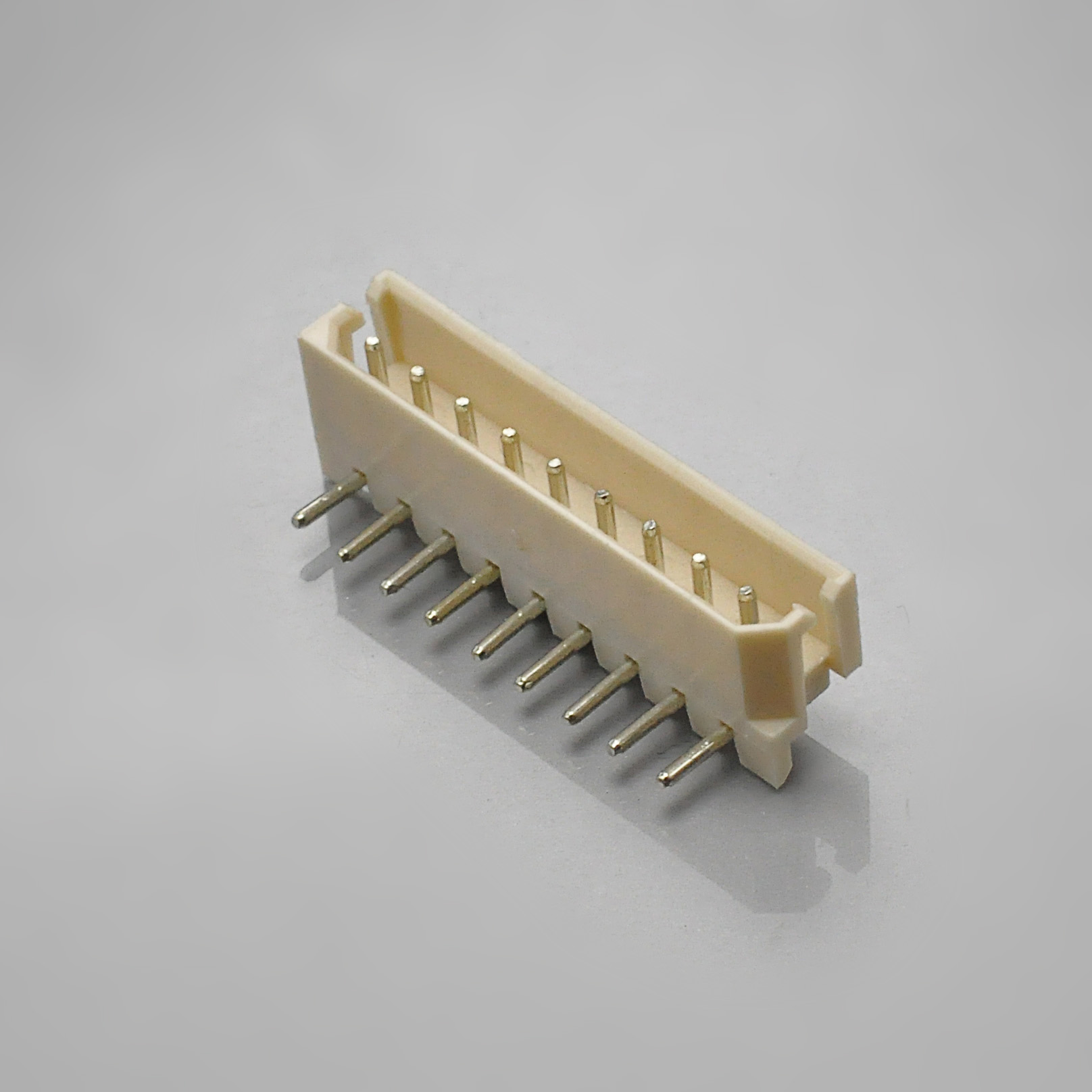
KONNRA KR2500 right angle DIP type wafer, cross-referenced to Molex Mini-SPOX series 5268
One thing the cross-reference does not carry across is the vocabulary. Molex calls the board-side part a plug assembly and describes the wire-side half as a receptacle; KONNRA calls the board-side part a wafer. If you are searching either catalogue, the four numbers above — 5263, 5264, 5267, 5268 — are the ones that work. They appear on none of KONNRA’s pages, which is the mirror image of the problem on this catalogue’s other cross-references: here the numbers are right and the words differ, rather than the other way round.
2. The insulation window: 1.6mm against a 1.15mm to 1.9mm original
This is the one number to check before anything else, and it is arithmetic rather than judgement.
| Parameter | Molex Mini-SPOX | KONNRA KR2500 | Overlap |
|---|---|---|---|
| Conductor size | AWG #22, #24, #26, #28 | AWG 22# – 28# | all four gauges |
| Insulation outside diameter | φ1.15mm to φ1.9mm | 1.6mm maximum | φ1.15mm to 1.6mm |
The wire range agrees perfectly. The insulation window does not. Molex specifies a window — a floor and a ceiling — of 0.75mm width. KONNRA publishes a ceiling of 1.6mm and, on every page it publishes, no floor at all.
Two consequences follow, and the second is the one that costs money.
A wire between 1.6mm and 1.9mm of insulation is inside Molex’s specification and outside KONNRA’s. That is a 0.30mm band, and it is not a hypothetical one: Molex rates 22 AWG at 3.0A and explicitly permits insulation up to φ1.9mm on it. Heavier-gauge hook-up wire in the 22 AWG class commonly lands in the 1.7mm to 1.9mm range. So the gauge Molex rates highest is the gauge most likely to fall outside the replacement’s published window.
And because no floor is published, nothing stops a wire that is too thin. Molex’s floor of φ1.15mm exists for a reason: the insulation barrel has to close on something, and below a certain diameter the crimp is not doing its job. A designer reading only KONNRA’s pages has no way to know that 1.15mm is the bottom of the qualified range. This is the quietest way for the cross-reference to fail — the wire crimps, the harness looks correct, and the joint is outside the qualified window at the wire-selection stage rather than at the test bench.
What to do with it: measure the finished outside diameter of your actual wire — the 1.15 – 1.90mm window is a property of the wire, not the gauge — and put the measurement in the RFQ. If your wire is between 1.6mm and 1.9mm, ask for the insulation crimp height for your wire against the terminal drawing rather than the specification table, because the table is written for a narrower window than the original’s.
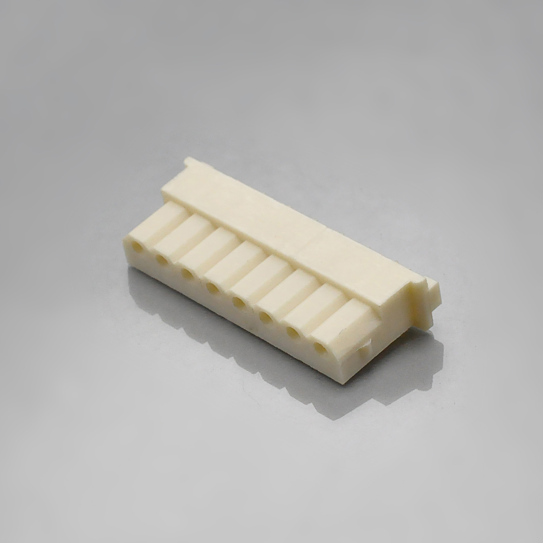
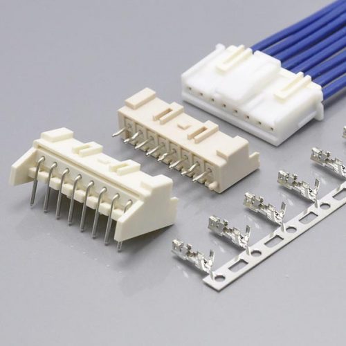
KONNRA KR2500 series 2.50mm pitch housing, the wire-side part governed by the insulation window
3. The circuit count: KONNRA’s tables say 16, the original ends at 15
This is the only figure in KONNRA’s documentation that the original cannot match, and it is also the only place where KONNRA’s own documents disagree with each other.
Here is every published circuit range:
| Source | Range published |
|---|---|
| Molex Mini-SPOX family page | 2 – 15 |
Molex PS-5264-001 §2.0 and §6.0 |
2 – 15 |
Molex 5267 vertical plug, 22035**5 family |
2 – 12, 14, 15 — 13 absent |
Molex 5267 vertical plug with swaged tails, 999909** family |
2 – 13 — 14 and 15 absent |
| Molex 5268 right-angle plug | 2 – 15 continuous |
| Molex 5264 housing | 2 – 15 continuous |
| KONNRA product page, at-a-glance table | 2-16pin |
| KONNRA component pages — housing, terminal, both wafers | 2P~16P |
| KONNRA specification §8.0 force table | 2 – 16 |
| KONNRA product page, Overview prose | 2 to 15 |
Molex has a 16-circuit gap and KONNRA has a 15-circuit disagreement. If your design needs 16 positions, there is no Molex Mini-SPOX part to cross-reference away from — and the figure on KONNRA’s own sheet is the one with no counterpart in the original catalogue.
KONNRA’s Overview paragraph is the document that agrees with Molex, and the reason is visible in the text. Put the two passages side by side:
- Molex: “Rugged automobile and industrial applications can be subject to shock, vibration or rough handling that can dislodge terminals and cause signal interference. Mini-SPOX Wire-to-Board Connector System features a friction lock for secure mating retention. High retention force provides electrical reliability in rugged environments.”
- KONNRA: “In automotive and industrial applications, frequent exposure to shock, vibration or rough handling can dislodge terminals and cause signal interference, posing a serious challenge to the robustness of the equipment. However, the KR2500 wire-to-board connector series, with its unique friction-lock design, ensures that mating is securely fastened and provides excellent electrical reliability even in harsh environments.”
The sentences track each other claim for claim, and so do the two that follow — the polarisation paragraph and the board-real-estate paragraph both have the same structure in both documents, and the closing paragraph of both ends in a circuit count. Molex’s reads “…available in 2 to 15 circuit single-row connectors in vertical and right-angle configurations”; KONNRA’s reads “…offers single row connectors for 2 to 15 circuits in both vertical and right-angle configurations”.
So the 2–15 in KONNRA’s Overview is the original’s figure carried across in the text, while KONNRA’s own tables claim one circuit more. I am not going to tell you which is right — that is a question for the supplier, and it is a reasonable one to ask. But the practical position is unambiguous: configure from a specific part number and get the count confirmed in writing, and do not plan a 16-circuit harness against either document without that confirmation.
There is also a Molex-side subtlety worth knowing before you order, because it has nothing to do with KONNRA. In Molex’s own vertical plug family, the standard 22035**5 parts run 2 through 12, then 14 and 15 — there is no 13 — while the swaged-tail 999909** variant runs 2 through 13 and stops there. So a 13-circuit vertical design must use the swaged-tail plug, and a 14- or 15-circuit vertical design must use the standard one. The right-angle plug and the housing both run 2 to 15 continuously, so a 13-circuit design is easier to satisfy horizontally than vertically. KONNRA publishes a single continuous 2P~16P across all four of its parts, which — if it holds — removes that gap.
4. Insertion and withdrawal force: identical to seven circuits, then a divergence
Both manufacturers publish a full insertion and withdrawal force table by circuit count, and both are unusually complete. This is the section that most directly answers “is it the same interface?”
KONNRA §8.0 gives insertion and withdrawal for 2 to 16 circuits, at initial and after 30 mating cycles. Units kgf.
| Circuits | 2 | 3 | 4 | 5 | 6 | 7 | 8 | 9 | 10 | 11 | 12 | 13 | 14 | 15 | 16 |
|---|---|---|---|---|---|---|---|---|---|---|---|---|---|---|---|
| Insertion, max | 1.70 | 2.30 | 2.90 | 3.50 | 4.10 | 4.70 | 5.30 | 5.90 | 6.50 | 7.10 | 7.70 | 8.30 | 8.90 | 9.50 | 10.10 |
| Withdrawal, min, initial | 0.65 | 0.70 | 0.75 | 0.80 | 0.90 | 1.00 | 1.10 | 1.20 | 1.30 | 1.40 | 1.50 | 1.60 | 1.70 | 1.80 | 1.90 |
| Withdrawal, min, after 30 cycles | 0.55 | 0.60 | 0.65 | 0.70 | 0.80 | 0.90 | 1.00 | 1.10 | 1.20 | 1.30 | 1.40 | 1.50 | 1.60 | 1.70 | 1.80 |
Both ladders are exact. Insertion force follows I.F. = 0.50 + 0.60 × circuits at all fifteen published rows — 0.50 + 1.20 = 1.70 at two circuits, 0.50 + 9.60 = 10.10 at sixteen. Withdrawal follows a two-part rule: it steps by 0.05 kgf per circuit from 2 to 5, then by 0.10 kgf per circuit from 5 to 16. And the after-30-cycles column is exactly 0.10 kgf below the initial column at every one of the fifteen rows — a constant absolute loss, which costs 15% of the retention at two circuits and 5% at sixteen.
Molex PS-5264-001 §6.0 publishes the same measurement for 2 to 15 circuits, in three columns: 1st, 6th and 30th mate. Two things about that table are worth noting before comparing. Molex’s insertion column is identical at 1st and 6th mate at every row, and its withdrawal column is identical at 6th and 30th mate at every row — so the three columns collapse into two distinct ladders. And Molex’s withdrawal ladder is not monotonic: it rises to 1.15 kgf at 8 circuits, drops back to 1.08 kgf at 9, then resumes climbing to 1.80 at 15. The insertion column dips at the same row, from 7.8 kgf to 6.4 kgf and back to 7.0.
The withdrawal comparison, circuit by circuit
| Circuits | Molex, 1st mate | KONNRA, initial | Molex, 30th mate | KONNRA, after 30 | Difference at 30 cycles |
|---|---|---|---|---|---|
| 2 | 0.65 | 0.65 | 0.55 | 0.55 | none |
| 3 | 0.70 | 0.70 | 0.60 | 0.60 | none |
| 4 | 0.75 | 0.75 | 0.65 | 0.65 | none |
| 5 | 0.80 | 0.80 | 0.70 | 0.70 | none |
| 6 | 0.90 | 0.90 | 0.80 | 0.80 | none |
| 7 | 1.00 | 1.00 | 0.90 | 0.90 | none |
| 8 | 1.15 | 1.10 | 1.00 | 1.00 | none |
| 9 | 1.08 | 1.20 | 0.90 | 1.10 | +0.20 |
| 10 | 1.20 | 1.30 | 1.00 | 1.20 | +0.20 |
| 11 | 1.32 | 1.40 | 1.10 | 1.30 | +0.20 |
| 12 | 1.44 | 1.50 | 1.20 | 1.40 | +0.20 |
| 13 | 1.56 | 1.60 | 1.30 | 1.50 | +0.20 |
| 14 | 1.68 | 1.70 | 1.40 | 1.60 | +0.20 |
| 15 | 1.80 | 1.80 | 1.50 | 1.70 | +0.20 |
Read the bold cells: the two tables are numerically identical for 2 through 7 circuits, at both first mate and after 30 cycles, and they converge again at 1.80 kgf for 15 circuits at first mate. Fourteen of the twenty-eight comparable figures are exact matches.
That is the single strongest piece of evidence in this article that the two connectors are the same interface. Withdrawal force is the property that emerges from the housing’s friction lock, the terminal lance, the plug geometry and the contact spring all working together. Two independent manufacturers publishing the same number at the same circuit count, across six consecutive sizes, is not the sort of thing that happens by coincidence.
The divergence from 8 circuits up follows directly from the anomaly in Molex’s own table. Between 8 and 15 circuits, KONNRA’s ladder is a straight line while Molex’s kinks at 9 and resumes at 10. By 13 circuits — five rows past the kink — the two differ by only 0.04 kgf at first mate (1.60 against 1.56), which is inside the measurement noise of a hand-pulled force gauge. The apparent disagreement is mostly the shape of one table, not a difference in the parts.
The one difference that is real and worth planning around is the after-30-cycles figure above 8 circuits, where KONNRA publishes exactly 0.20 kgf more at every size from 9 to 15. A higher minimum after 30 mates is the better direction to be wrong in — it is a floor, not a ceiling — but it is a claim about wear that has to have been measured on the KR2500 to be a KR2500 figure. If your design sits between 9 and 15 circuits, ask whether that column was tested on this assembly. It is a fair question and a cheap one.
Insertion force: KONNRA’s ceiling is about half of Molex’s at low circuit counts
The insertion columns differ much more than the withdrawal columns, and in the direction that favours assembly.
| Circuits | Molex, insertion max (1st mate) | KONNRA, insertion max | Ratio |
|---|---|---|---|
| 2 | 3.6 kgf | 1.70 kgf | Molex is 2.1× higher |
| 5 | 6.0 kgf | 3.50 kgf | 1.7× |
| 8 | 7.8 kgf | 5.30 kgf | 1.5× |
| 10 | 7.0 kgf | 6.50 kgf | 1.1× |
| 12 | 8.2 kgf | 7.70 kgf | 1.1× |
| 15 | 10.0 kgf | 9.50 kgf | 1.05× |
Insertion force is a ceiling — the highest force the mated pair should require. A lower ceiling means the connector is specified to go together more easily, which matters on a manual assembly line and on a board that cannot take much insertion load. KONNRA’s published ceiling is less than half of Molex’s at two circuits and converges to within 5% by fifteen.
Read together with section 5, this is the KR2500’s clearest engineering case: it is specified to retain harder and to insert more easily than the part it replaces. Those two properties normally trade off against each other, which is what makes the pair of figures worth checking rather than assuming.
5. Retention and crimp strength: measure-for-measure stronger
Molex’s product specification publishes three retention figures; KONNRA publishes three comparable ones. All three comparisons favour the KR2500, and all three are on the same measurement convention — an axial force applied at 25 mm/minute on Molex’s side and 25.4 mm/minute on KONNRA’s, which is the same 0.5 inch per minute expressed two ways.
| Measurement | Molex PS-5264-001 |
KONNRA PS-KR2500-01 |
Difference |
|---|---|---|---|
| Terminal insertion force into housing | 1.5 kgf (14.7N) max | 1.0 kgf (9.8N) max | −33% — easier to assemble |
| Terminal retention force, terminal in housing | 1.5 kgf (14.7N) min | 2.0 kgf (19.6N) min | +33% — harder to pull out |
| Header pin retention force | 1.0 kgf (9.8N) min | 1.5 kgf (14.7N) min | +50% — harder to dislodge |
All three move in the right direction, and that is unusual enough to be worth stating carefully rather than as a slogan. The two retention figures are minimums and the insertion figure is a maximum, so the KR2500’s published position is: holds harder, pushes in more easily. Molex’s own family page explains why that pairing is the one that matters — “High retention force provides electrical reliability in rugged environments” — and the KR2500’s specification claims a higher floor on exactly that property.
And a detail that connects this section to section 4, which is worth having at a design review. The terminal retention of 2.0 kgf minimum is per terminal. The withdrawal force of the mated pair is 0.65 kgf at two circuits and 1.90 kgf at sixteen. Both scale with position count, so the ratio holds at about 6:1 at two circuits and 17:1 at sixteen — meaning that in every configuration the connector separates at the mating interface long before a properly seated terminal moves. The mating interface is the intended release point, which is the property you want, and it follows from the two published figures rather than being a design claim. Note that the margin is thinnest at the two-circuit end, so if your harness is short, that is where the assembly instruction matters most.
Crimp pull-out strength: higher at all four gauges
Both manufacturers publish a crimp strength per wire gauge, and both cover the same four gauges. This is the comparison that most directly affects whether a harness survives a pull test.
| Wire | Molex, crimping pull-out force, min | KONNRA, crimp strength, min | Difference |
|---|---|---|---|
| 22 AWG | 4.0 kgf (39.2N) | 4.54 kgf | +13.5% |
| 24 AWG | 3.0 kgf (29.4N) | 3.63 kgf | +21% |
| 26 AWG | 2.0 kgf (19.6N) | 2.27 kgf | +13.5% |
| 28 AWG | 1.0 kgf (9.8N) | 1.36 kgf | +36% |
KONNRA’s floor is above Molex’s at every gauge in the range, largest in relative terms at the lightest wire. Both ladders descend in the same proportion with gauge, so this is a uniform uplift rather than a claim concentrated at one end.
The full KONNRA crimp table is also worth publishing here, because this one behaves correctly. All four rows, from §6.5:
| 22 AWG | 24 AWG | 26 AWG | 28 AWG | |
|---|---|---|---|---|
| Conductor crimp width | 1.50 ± 0.15 | 1.50 ± 0.15 | 1.50 ± 0.15 | 1.50 ± 0.15 |
| Conductor crimp height | 0.88 ± 0.05 | 0.83 ± 0.05 | 0.80 ± 0.05 | 0.70 ± 0.05 |
| Insulation crimp width | 2.00 Max | 2.00 Max | 2.00 Max | 2.00 Max |
| Insulation crimp height | 1.90 ± 0.1 | 1.80 ± 0.1 | 1.70 ± 0.1 | 1.45 ± 0.1 |
| Crimp strength, min | 4.54 kgf | 3.63 kgf | 2.27 kgf | 1.36 kgf |
| Stripping length | 1.6 – 2.1 mm | 1.6 – 2.1 mm | 1.6 – 2.1 mm | 1.6 – 2.1 mm |
Both ladders run the right way. Conductor crimp height rises with conductor size — 0.70mm at 28 AWG up to 0.88mm at 22 AWG — and the insulation crimp height rises with insulation size in the same direction, from 1.45mm at 28 AWG to 1.90mm at 22 AWG. That is the physically expected behaviour for an insulation barrel, and it is worth pointing out because it is not universal on this catalogue: the insulation crimp height in the 2.50mm Mini-SPOX table climbs from 1.45 to 1.90 as the wire gets heavier, while the corresponding table on another series in the same catalogue uses a ladder that descends as the wire gets heavier.
And the top of the insulation ladder lines up with the original’s window rather than with KONNRA’s own published ceiling. The 22 AWG insulation crimp height is 1.90 ± 0.1mm, and Molex permits insulation up to φ1.9mm. That agreement is the reason section 2 matters so much: the crimp data says the tooling is built for insulation up to 1.9mm, while the wire-selection pages say the series takes 1.6mm maximum. The crimp table and the wire window on KONNRA’s own documents do not agree, and the crimp table is the one that matches the original. Ask before you exclude a 1.8mm wire.
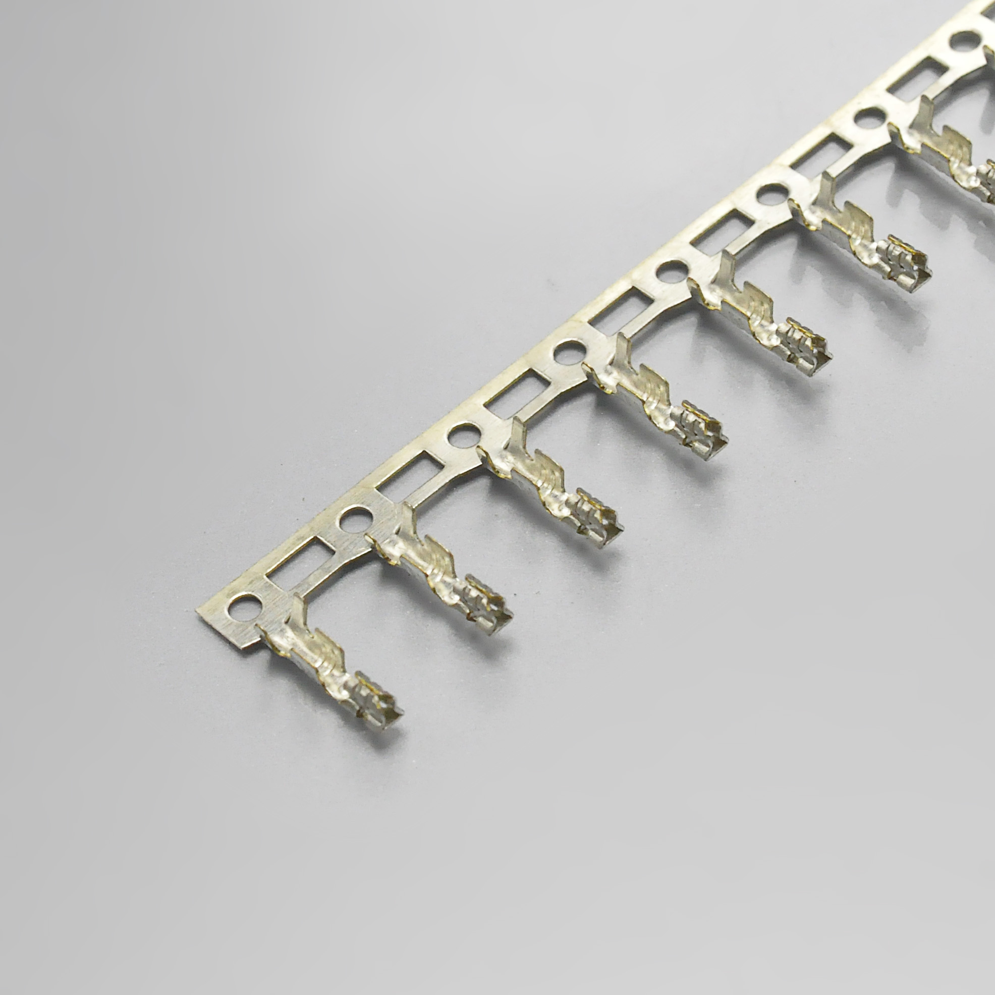
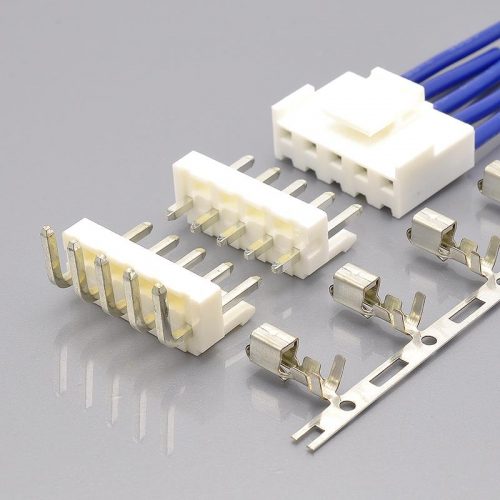
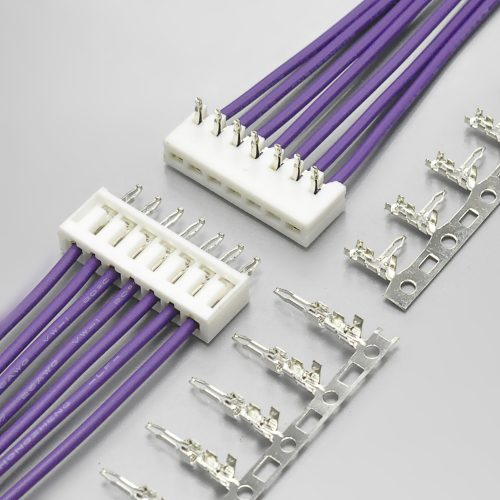
KONNRA KR2500 series 2.50mm pitch terminal, the crimp contact compared in sections 5 and 6
6. Electrical performance: three exact matches and one figure that is missing
The electrical block is the most reassuring part of this comparison, because three of the four parameters are identical and the fourth is a gap rather than a difference.
| Parameter | Molex PS-5264-001 |
KONNRA PS-KR2500-01 |
Assessment |
|---|---|---|---|
| Rated voltage | 250V AC (rms) / DC | 250V AC/DC | match |
| Contact resistance | 20mΩ max | 20mΩ max | match |
| Insulation resistance | 1,000MΩ min at 500V DC | 1,000MΩ min at 500V DC | match |
| Dielectric strength | 1,000V AC (rms) for 1 minute | 1,000V AC for 1 minute | match |
| Contact resistance on the crimped portion | 5mΩ max | not published | gap |
| Dry-circuit measurement condition | 20mV max, 10mA max | 20mV max, 100mA max | worth confirming |
Four parameters, four matches, including the one I would have expected to differ. A 250V rating, a 20mΩ contact resistance, a 1,000MΩ insulation resistance and a 1,000V AC dielectric test appearing identically on a replacement’s sheet and an original’s sheet is a strong indication that the KR2500’s electrical block was written against the same requirement as Molex’s.
Two qualifications belong with that, and neither is a criticism of the numbers themselves.
The crimp-portion contact resistance is specified by Molex and absent from KONNRA’s. Molex §4-1-4 requires 5mΩ maximum measured across a crimped joint. Contact resistance at the crimp is a different failure mode from contact resistance at the mating interface — it is where a bad crimp height or an under-specified conductor barrel shows up — and it is the measurement that catches a harness problem before it becomes a field return. KONNRA’s specification does not publish a limit for it. If you are qualifying a harness rather than a connector, ask for that figure; the crimp heights in section 5 are the inputs, but 5mΩ is the acceptance criterion.
The two dry-circuit conditions are not the same, and it is a real difference rather than a rounding one. Molex measures at 20mV maximum and 10mA maximum; KONNRA measures at 20mV maximum and 100mA maximum. Both are described as dry-circuit measurement of a 20mΩ limit, but a tenfold difference in test current across a contact whose resistance is dominated by the constriction at the contact interface is a difference in the test, not just in the paperwork. It does not make either number wrong. It does mean the two 20mΩ limits are not automatically the same measurement, and if your qualification pack treats a 20mΩ limit as a transferable number, that is the line to check.
One more electrical row matches that is easy to overlook: the current rating at high circuit counts. KONNRA publishes a single 3A (22AWG). Molex’s headline rating is 3.0A per contact and its family page advertises 4.0A as the maximum derating current — but Molex’s own derating table resolves the apparent difference:
| Molex derating reference (22 AWG) | 2 circuits | 8 circuits | 15 circuits |
|---|---|---|---|
| Allowable current | 4.0A | 3.5A | 3.0A |
Molex’s 3.0A is the fifteen-circuit figure; at two circuits the same wire is allowed 4.0A. So KONNRA’s flat 3A equals Molex’s worst-case, fully-loaded figure, and is more conservative than Molex at low circuit counts. A designer comparing “3A replacement” against “4A original” is comparing against a number that only applies to a two-circuit harness. On the other hand, Molex publishes a full per-gauge ladder — 3.0A at 22 AWG, 2.5A at 24, 2.0A at 26, 1.5A at 28 at fifteen circuits — and KONNRA publishes no per-gauge derating at all. If your design uses 26 or 28 AWG, Molex’s own sheet says 2.0A and 1.5A; KONNRA’s single 3A figure is not a rating for those gauges.
7. The environmental programme: eleven tests against thirteen
Both specifications publish a substantial environmental block, and this is where the cross-reference is thinnest in coverage rather than weakest in values.
| Test | Molex PS-5264-001 |
KONNRA PS-KR2500-01 |
Same? |
|---|---|---|---|
| Repeated insertion/withdrawal | 30 cycles at ≤10/min → 40mΩ max | 30 cycles at ≤10/min → 40mΩ max | identical |
| Temperature rise | 30°C max, UL498 method, all terminals in series | 30°C max at rated current | same limit |
| Vibration | 1.5mm P-P, 10–55–10 Hz, 2h each of 3 axes, cable fixed, DC 1mA passed → 40mΩ, 1.0µs | 1.5mm P-P, 10–55–10 Hz, 2h each of X, Y, Z → 40mΩ, 1µs | same limit, Molex states the cable fixing and test current |
| Mechanical shock | 490 m/s² (50G), half-sine, 11ms, 6 directions, 3 shocks each — 18 total, DC 1mA | 490 m/s² (50g), 3 strokes in each of X, Y, Z → 40mΩ, 1µs | Molex is more severe |
| Heat resistance | 105±2°C, 96h → 40mΩ | 105±2°C, 96h → 40mΩ | identical |
| Cold resistance | −55±3°C, 96h → 40mΩ | −40±2°C, 96h → 40mΩ | 15°C apart |
| Humidity | 60±2°C, 90–95% RH, 96h → 40mΩ, 100MΩ min | 40±2°C, 90–95% RH, 96h → 40mΩ, 100MΩ min | Molex tests 20°C hotter |
| Temperature cycling | −55±3°C ↔ +105±2°C, 30 min each, 5 cycles → 40mΩ | −40±2°C ↔ +105±2°C, 30 min each, 5 cycles → 40mΩ | same cycle count |
| Salt spray | 35±2°C, 5±1%, 48±4 hours → 40mΩ | 35±2°C, 5±1%, 8 hours → 40mΩ | Molex runs 6× longer |
| SO2 gas | 50±5ppm at 40±2°C for 24h → 40mΩ | not published | missing |
| Ammonia (NH3) gas | 28% solution vapour, 40 minutes → 40mΩ | not published | missing |
| Solderability | 245±3°C, 3±0.5s, 1.2mm immersion → 95% wetting | 245±5°C, 3±0.5s → 95% wetting | Molex tighter on temperature |
| Resistance to soldering heat | Dip: 260±5°C, 5±0.5s. Hand iron: 370–400°C, 5s max | Wave profile only: 250°C max peak, 3–5s | Molex hotter and covers hand repair |
Three of these rows matter more than the others, and the first is a qualitative gap rather than a number.
The two corrosive-gas tests have no counterpart on KONNRA’s sheet. Molex runs an SO2 gas exposure at 50±5ppm for 24 hours and an ammonia exposure in 28% solution vapour for 40 minutes, both with a 40mΩ acceptance limit. Those two tests are the ones that speak to contaminated and agricultural-industrial environments, and they are the standard battery for automotive and appliance qualification in Japan. Their absence does not mean the KR2500 would fail them; it means the data does not exist yet. If your qualification plan references corrosive-gas exposure, this is the single largest item to raise, and it is a test a supplier can run rather than a design change.
Salt spray is eight hours against forty-eight. Same solutions, same temperature, same acceptance limit, six times the exposure on Molex’s side. Eight hours is a short salt-spray exposure by any reading; 48 hours is a working day of continuous spray. For an indoor assembly this rarely matters; for anything with a condensation or coastal duty cycle it is the difference between a qualified part and an untested one.
And the humidity test runs 20°C cooler. Molex exposes mated connectors to 60±2°C at 90–95% relative humidity; KONNRA exposes them to 40±2°C at the same humidity, both for 96 hours, both accepting 40mΩ and 100MΩ minimum. The acceptance criteria are identical — the stress is not. Humidity damage is thermally driven, so 60°C is materially more severe than 40°C at the same relative humidity.
Two rows are exact, and one of them is a good sign. Heat resistance at 105±2°C for 96 hours and durability at 30 cycles are identical on both sheets, down to the acceptance limit. Those two are the tests that most directly corroborate the headline lifetime and temperature claims, and having them match puts the ±0.20 kgf difference in the force table into perspective.
One framing point on the thermal block as a whole. KONNRA’s cold-side tests — cold resistance and thermal cycling — are run at −40°C against Molex’s −55°C, and the published operating range is −40°C to +105°C against −55°C to +105°C. The rating and the test agree with each other on both sides; they simply disagree with each other across the cross-reference. That is a 15°C shortfall at the cold end, and it is the second-largest item on this page after the corrosive gases. For a consumer or indoor-industrial application in a conditioned environment it costs nothing. For automotive under-hood, outdoor equipment or cold-chain, it is a hard boundary and it needs to be resolved before the part is specified.
Finally, a small technical point that shows the wave profile is real and matched to the product. KONNRA publishes only a wave-soldering profile — 3 to 5 seconds at 250°C maximum peak, 60 to 150 seconds above 217°C, preheat 150–180°C — and no reflow profile at all. That is correct for this series, because §2.0 publishes only DIP wafers (a straight DIP 180° and a right-angle DIP 90°), and both Molex plugs are through-hole parts too. A series with no SMT option should not publish a reflow profile, and this one does not. The one inconsistency is a single word: §9.0 is titled “Wave soldering profile” while its closing note reads “Please check the reflow soldering condition by your own devices beforehand.” The profile itself is a wave profile; the note borrowed the wrong noun. Note the temperature ceiling, though: 250°C maximum against Molex’s qualified 260±5°C for 5 seconds, and no hand-soldering-iron condition on KONNRA’s sheet at all. A board whose wave runs at 255°C is inside Molex’s specification and above KONNRA’s.
8. Materials, plating, and the resin that absorbs water
Both sides specify the same generic materials, and the differences are in what each one is willing to write down.
| Component | Molex | KONNRA |
|---|---|---|
| Housing resin | Nylon · described as a high heat resistant polyamide · natural | PA66 UL94 V-0 · beige |
| Terminal base metal | Phosphor bronze | Phosphor bronze |
| Terminal plating | Tin, plating min 0.889µm mating / 0.914µm termination | Tin over nickel — thickness not published |
| Plug contact | Tin, plating min 4.064µm mating and termination | Brass contact, tin over nickel — thickness not published |
| Flammability | 94V-0 | UL94 V-0 |
| Low-halogen | Not Low-Halogen per IEC 61249-2-21 | not published |
| RoHS / REACH | EU RoHS compliant per EU 2015/863; REACH SVHC not contained | not published |
| Substances of interest declared | PFAS, DBDPE, DP | none declared |
The terminal base metal agrees exactly — phosphor bronze on both sides — and the plating construction is the more interesting comparison. KONNRA specifies tin over nickel on every plated surface, including the wafer contacts and solder tails. Molex’s specification calls out tin with the thickness, and no nickel under-plate. A nickel barrier is the construction that keeps a matte-tin surface stable at temperature by preventing copper from diffusing into the tin layer, so on the face of it KONNRA’s callout is the more conservative one.
But only one side publishes a thickness, and thickness is what makes a barrier mean anything.
| Plating callout | Molex | KONNRA |
|---|---|---|
| Plug contact, mating | 4.064µm minimum | tin over nickel, thickness not stated |
| Terminal, mating | 0.889µm minimum | tin over nickel, thickness not stated |
| Terminal, termination | 0.914µm minimum | tin over nickel, thickness not stated |
Molex publishes three separate minimum thicknesses in micrometres, at the third decimal place. KONNRA publishes a plating system and no thickness at all — neither for the tin nor for the nickel layer that is the reason to prefer the system. A nickel under-plate with no thickness figure is an intention rather than a specification, and it is the first thing to ask for if your qualification plan calls out plating thickness or if you are running a solderability or whisker assessment.
The halogen and RoHS rows are gaps rather than differences, and one of them points the other way. Molex declares this part “Not Low-Halogen per IEC 61249-2-21” — that is a statement that halogen content exceeds the low-halogen threshold, made voluntarily. If your programme requires low-halogen parts, Mini-SPOX is not one on Molex’s own declaration, and KONNRA’s documents are silent. Molex also publishes EU RoHS compliance against EU 2015/863, a REACH SVHC statement with a dated assessment, and a short list of declared substances of interest. KONNRA’s specification and pages publish none of these. For most applications that costs nothing; for a European OEM with a documented compliance file, it is three declarations to request rather than two parts to compare.
The water-absorption note is the best piece of engineering writing in either document
Molex’s specification carries 31 numbered application notes, and two of them describe a behaviour that no data table can capture. They are worth quoting in full because they change how you read the force tables in section 4.
Note 30: “The housing material of this product is made from a high heat resistant polyamide. The soldering condition and the water absorption properties of the housing material may cause blistering on the housing surface. Because this blister is not caused by property change, it does not damage the product’s features.” Note 31: “Because the receptacle housing material of this product is using polyamide, the water absorption status of the housing material might change insertion force, withdrawal force, or the feeling of insertion. Its excessive water absorption may weaken the click feeling of the lock when mating. However it does not damage the product’s features and functions.”
In two sentences, Molex is saying that the force numbers in its own table are not stable: the housing’s moisture content moves the insertion force, the withdrawal force and the feel of the lock. A polyamide housing that has absorbed water will mate with a softer click. That has three practical consequences, and none of them appears anywhere in KONNRA’s documentation.
- A force measurement is a measurement at one moisture content. If you are comparing a supplier’s sample against a 0.65 kgf or 1.90 kgf figure, the housing’s conditioning matters as much as the gauge.
- “The click felt wrong” is a reportable assembly observation, not a defect. Operators notice the difference before a gauge does, and the note tells you what to record when they do.
- Reflow blistering of the housing surface is declared non-defect. That matters for incoming inspection criteria: if your AQL plan rejects surface blistering, it will reject conforming parts.
And a related note that is the single most useful line for anyone building a harness. Molex note 15: “Please tie the cable at least 50mm away from the edge of the connectors and try to ensure that the force is applied evenly on all the wires.” Molex note 17 adds that the housing should be withdrawn “slowly, axially and straightly”, and note 16 warns that a constant pulling force on a mated connector damages the contact area and the crimp. Those three notes are the harness drawing instructions on this system, and KONNRA’s specification contains no equivalent. If you are issuing a harness drawing, they belong on it.
9. What the documents do not publish
Everything below is genuinely absent from KONNRA’s documents and present in Molex’s, so each line is a specific request rather than a general reservation. Nothing here is estimated.
| Item | Molex figure | KONNRA status |
|---|---|---|
| Wire insulation floor | φ1.15mm | not published — only a 1.6mm ceiling. Section 2 |
| Per-gauge current derating | 3.0A / 2.5A / 2.0A / 1.5A at 15 circuits for 22 / 24 / 26 / 28 AWG | not published — a single 3A(22AWG) |
| Crimp-portion contact resistance | 5mΩ max | not published |
| Plating thickness | 4.064µm · 0.889µm · 0.914µm minimum | not published |
| PCB thickness | 1.60mm recommended | not published |
| PC tail length | 3.50mm | not published |
| SO2 gas and ammonia gas exposures | 50±5ppm / 24h · 28% vapour / 40min | not published |
| Hand-soldering-iron condition | 370–400°C, 5 seconds max | not published |
| Salt spray duration | 48±4 hours | 8 hours — published but 6× shorter |
| Low-halogen status | Not Low-Halogen (explicit) | not published |
| RoHS / REACH declarations | EU 2015/863 compliant; SVHC not contained; PFAS, DBDPE, DP declared | not published |
| Application notes | 31 numbered notes covering washing, live-circuit mating, wire fixing, repair and handling | none — a single remark in §10.0 |
| Revision history | 11 revisions from 1988 to 2020, each with ECN and named writer and checker | no history — Edition A1, issued and revised on the same date |
| Change notification | 5 product change notifications published on the part page | §10.0 states revisions “will not be announced in advance” |
| 16-circuit availability | does not exist — the system ends at 15 | claimed as 2P~16P on all four component pages |
Two of these rows are worth acting on before anything else. The insulation floor is the one that silently excludes a wire the original approves, and the corrosive-gas gap is the one that could fail a qualification plan rather than a design review. Both are answerable by the supplier; neither requires an engineering change.
And the packaging row is a small illustration of how the two documents differ in kind. KONNRA publishes a Package Specification for this series — a separate PDF alongside the product specification and the engineering drawing, which is more documentation than most series in its catalogue carry. Molex publishes one too (SPK-5267-001-001.pdf), and additionally states Bag as the packing type on the part page and Reel for the crimp terminal. KONNRA’s package specification is published as vector artwork with no extractable text, so the packing quantity and unit cannot be read from it without opening it as a drawing. That is not a flaw in the cross-reference; it is a reason to ask for the unit quantity in the quote rather than hunting for it.
10. Documentation practice, and the one measurement instruction I would not copy
Sections 1 through 9 compare hardware. This section compares the paperwork, because on a cross-reference that is going into a qualification file, the paperwork is part of the part.
The force tables were written on the same convention, with one exception
KONNRA §6.1 and Molex §4-2-1 both describe the same insertion-and-withdrawal test, at the same rate expressed two ways — 25.4±3 mm/minute and 25±3 mm/minute, which are both the customary 0.5 inch per minute. But KONNRA’s clause carries a qualifier that Molex’s does not.
- Molex §4-2-1: “Insert and withdraw connectors at the speed rate of 25±3mm/minute.”
- KONNRA §6.1: “Insert and withdraw connectors at the speed rate of 25.4±3mm/minute. (Excluding plastic detents)“
KONNRA excludes the plastic detents — the friction-lock feature — from the force measurement; Molex does not state an exclusion. That qualifier sits directly under the table compared in section 4, and it matters there: the friction lock is exactly the feature that produces the retention force, and a measurement that excludes it is measuring the contact springs plus the housing walls rather than the whole mated pair.
So the fourteen exact matches in section 4 should be read with that caveat attached. Two identical ladders measured on the same convention are strong evidence of a shared interface, and the convergence at 1.80 kgf for 15 circuits is hard to explain any other way. But “identical numbers” and “identical test” are not the same claim, and if the numbers matter to your acceptance criteria, the exclusion clause is the line to raise. It is a one-line question with a one-line answer, and it is the sort of question that separates a documented cross-reference from an assumed one.
One retention instruction is written in the wrong direction, and the original shows the correct one
The mechanical block contains a wording defect that changes how a test is run. The two documents side by side make it unambiguous.
| Document | Item | Instruction |
|---|---|---|
Molex PS-5264-001 §4-2-4 |
Crimp Terminal Retention Force | “Apply axial pull out force at the speed rate of 25±3 mm/minute…” |
Molex PS-5264-001 §4-2-5 |
Header Terminal Retention Force | “Apply axial pull out force at the speed rate of 25±3 mm/minute…” |
KONNRA PS-KR2500-01 §6.3 |
Terminal/Housing Retention Force | “Apply axial pull out force at the speed rate of 25.4±3mm/minute…” |
KONNRA PS-KR2500-01 §6.4 |
Pin Retention Force | “Apply axial push force at the speed rate of 25.4±3mm/minute.” |
Both of Molex’s retention items say pull out. KONNRA’s equivalent pair says pull out for the terminal and push for the pin.
A pin-retention test that pushes a post into the wafer cannot measure retention. The item’s own heading and its requirement — 1.5 kgf (14.7N) minimum — only make sense as a pull-out measurement, and the corresponding Molex clause (1.0 kgf minimum) is written as one. If you are writing a test procedure from this document, specify pull-out yourself and do not copy the §6.4 sentence. The requirement is stronger than Molex’s and worth keeping; the verb is the part to change.
The revision practice is the biggest difference between the two documents
Molex PS-5264-001 |
KONNRA PS-KR2500-01 |
|
|---|---|---|
| Revision | J | A1 |
| Date | 2020/05/08 | 2022/02/26 (issued and revised on the same date) |
| Length | 20 sheets | 7 sheets |
| Revision history | 11 revisions from 1988/06/21 to 2020/05/08, each with a revision letter, date, ECN number, and a named written by and checked by | none |
| Independent check | Every revision names a checker — Rev J written by S.OKUMURA, checked by S.AKIYAMA | Signature block reads Written: Arvin · Checked: / · Approved: Min xinhao — the checked field is a stroke, not a name |
| Change notification | 5 product change notifications listed on the part page, including a 2023 equipment transfer affecting 5267 and 5268 | §10.0: “Any change or revision for the product specification will not be announced in advance. Please contact our sales representative for the latest information.” |
Three things are on the record here, and the third is the one to plan around.
Molex’s document has been revised eleven times since 1988 and names an independent checker on every revision. KONNRA’s is Edition A1 — the first edition — issued and revised on the same day, with the independent-check field left unfilled. That is not a statement about whether the connector works; it is a statement about how much independent review the document has had, and a qualification file that cites a specification should know the difference.
The two documents also differ in size by a factor of three, and the gap is almost entirely notes rather than tables. Molex’s 20 sheets include 31 application notes covering cleaning, live-circuit mating, wire fixing, board handling, repair limits and the moisture behaviour in section 8. KONNRA’s 7 sheets carry every test in section 7 and one closing remark. The measurements are there; the application guidance is not.
And §10.0 states that revisions will not be announced in advance. Molex notifies changes through published PCNs — the part page lists five, one of which transferred 5267 and 5268 production in 2023. On the KONNRA side the specification says, in advance, that you will not be told. For a catalogue part that is a procurement risk rather than a technical one, and the mitigation is procedural: record the revision you qualified against, and re-request the document rather than re-reading a saved copy. That is precisely the instruction §10.0 gives, and it is worth taking literally.
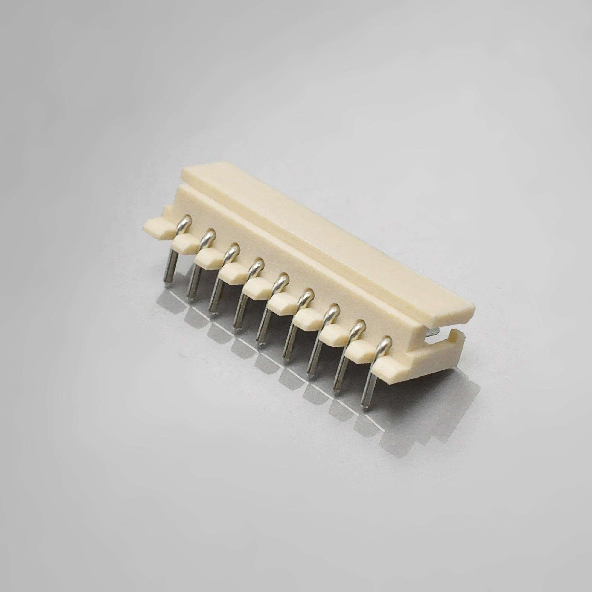
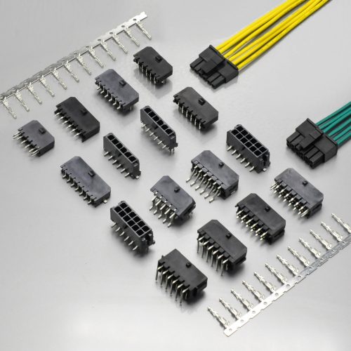
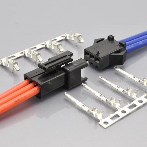
KONNRA KR2500 series 2.50mm pitch right angle DIP type wafer, one of the two board-side parts in this cross-reference
11. Identification guide: the four Molex numbers that map to the KR2500
Because Mini-SPOX is a system split across four series, the fastest way to use this cross-reference is to start from your own Molex part number. The plug numbers are issued per circuit count, so the pattern is what identifies the series.
| If your Molex part number looks like | It is | Series | KONNRA counterpart | Where its ratings live |
|---|---|---|---|---|
50375**3 |
Receptacle crimp housing, friction lock, natural | 5264 | Housing H25000***2201B |
Housing page |
087010** |
Receptacle crimp terminal, phosphor bronze, tin | 5263 | Terminal T25000PT0101B |
Terminal page |
22035**5 |
Plug assembly, vertical, through-hole | 5267 | Straight wafer (2500-dip180) |
Wafer page |
999909** |
Plug assembly, vertical, with swaged PC tails | 5267, second drawing | Straight wafer (2500-dip180) |
Wafer page |
22057**5 |
Plug assembly, right-angle, friction lock | 5268 | Right-angle wafer (2500-dip90) |
Wafer page |
Three checks are worth running before you compare any figure.
First: which half are you holding? Ratings are not distributed evenly across the four series. Molex’s insulation window of φ1.15mm to φ1.9mm and its full per-gauge current ladder live in the product specification because they belong to the terminal — the part the wire enters. Its plug page carries the 250V, 3.0A, 30-cycle, −55°C figures and the 1.60mm PCB thickness and 3.50mm PC tail data. If you compare a housing number against a plug figure you will conclude the parts disagree when they do not.
Second: does your circuit count exist in the part you need? In Molex’s vertical plug family, 13 is absent from the standard 22035**5 parts and 14 and 15 are absent from the swaged-tail 999909** parts. The right-angle plug and the housing both run 2 to 15 continuously. A 13-circuit vertical design has no standard part — and KONNRA publishes a continuous 2P~16P across all four of its parts, which is the one place where the replacement may be easier to use than the original.
Third: is the insulation diameter inside the window? This is section 2, and it is the check that most often decides the outcome. Measure the wire, not the gauge.
And one note on what KONNRA’s own numbers do and do not tell you. The four KONNRA part-number patterns are H25000***2201B (housing), T25000PT0101B (terminal) and the two wafers C2500RD***22T0101PB and C2500VD***22T0101PB — every one of them carries the 2500 series identity, with no borrowed prefix from another series and no ambiguity about which product line they belong to. The two wafer numbers are published in §2.0 and the assembly-type mapping to 5267 and 5268 comes from the two component pages rather than from the specification table, so if the straight-versus-right-angle assignment matters to your BOM, confirm which number is which in the quote.
12. Ten-point cross-reference checklist
- Measure your wire’s finished insulation diameter, not its gauge. Molex qualifies φ1.15mm to φ1.9mm; KONNRA publishes 1.6mm maximum and no floor. A 1.8mm wire is inside the original’s window and outside the replacement’s. Section 2.
- Confirm your circuit count in writing, and do not plan 16 against either document yet. KONNRA’s tables say 2–16 and its Overview says 2–15; Molex ends at 15. Section 3.
- If you need 13 circuits vertically, check which Molex plug you have. The standard vertical plug skips 13; the right-angle plug and the housing do not. Section 11.
- Expect 3A to be correct for 22 AWG and to be the only figure published. KONNRA’s single 3A(22AWG) equals Molex’s 15-circuit derating figure; Molex also publishes 2.5A at 24 AWG, 2.0A at 26 and 1.5A at 28, which KONNRA does not. Section 6.
- Treat the retention figures as the strongest part of the case. Terminal retention 2.0 kgf min against Molex’s 1.5; header pin retention 1.5 kgf min against 1.0; crimp pull-out higher at all four gauges. Section 5.
- Ask whether the force table excludes the plastic detents. KONNRA §6.1 says it does; Molex’s clause states no exclusion. The numbers match exactly for 2–7 circuits, and this is the one clause that qualifies that match. Section 10.
- Resolve the cold end before you design around it. −40°C on KONNRA’s sheet against −55°C on Molex’s, borne out by the cold-resistance and thermal-cycling tests on both sides. Section 7.
- Request the two missing environmental tests if your plan calls for them. Molex runs an SO2 gas exposure and an ammonia exposure; KONNRA publishes neither. Also note salt spray is 8 hours against Molex’s 48. Section 7.
- Ask for the plating thickness and the crimp-portion contact resistance. Molex publishes 4.064µm on the plug and 0.889µm / 0.914µm on the terminal, and a 5mΩ max crimp-joint limit; KONNRA publishes neither. Section 9.
- Record the revision you qualified against, and re-request it. KONNRA’s §10.0 states revisions will not be announced in advance, and the current edition is A1 with no revision history. Molex’s is at Rev J with eleven revisions and published change notices. Section 10.
13. Frequently asked questions
Is the KR2500 a drop-in replacement for the Molex Mini-SPOX?
On the interface, the evidence is strong; on one wire parameter, it needs checking first. All four cross-referenced part families are correct — housing 5264, terminal 5263, vertical plug 5267, right-angle plug 5268 — and the withdrawal-force ladder is numerically identical to Molex’s for 2 through 7 circuits at both first mate and after 30 cycles. Voltage, contact resistance, insulation resistance, dielectric strength, durability, wire gauge range and temperature upper limit all match. The parameter that does not match is the applicable wire insulation: KONNRA publishes 1.6mm maximum against Molex’s φ1.15mm to φ1.9mm.
What wire can I use?
AWG 22 to 28 on both sides — the gauge range matches exactly, and KONNRA publishes a crimp row for each of the four. The insulation outside diameter is where they differ: Molex qualifies φ1.15mm to φ1.9mm; KONNRA publishes 1.6mm maximum with no floor. Measure your wire and check it against the narrower window. Note that KONNRA’s own 22 AWG insulation crimp height of 1.90 ± 0.1mm matches Molex’s 1.9mm ceiling, so ask before you exclude a wire in the 1.6–1.9mm band.
What are the voltage and current ratings?
250V AC/DC on both sheets, exactly. Current is 3A at 22 AWG on KONNRA’s sheet, and 3.0A maximum per contact on Molex’s — but Molex’s 3.0A is its 15-circuit derating figure, and the same 22 AWG wire is allowed 4.0A at two circuits in Molex’s own derating table. Molex also publishes a full per-gauge ladder (3.0A / 2.5A / 2.0A / 1.5A for 22 / 24 / 26 / 28 AWG at 15 circuits); KONNRA publishes no per-gauge derating at all.
How many circuits does it come in?
Molex’s Mini-SPOX is a 2 to 15 circuit system. KONNRA’s product page and all four component pages say 2P~16P, and its force table runs 2 to 16, while its Overview paragraph says 2 to 15. The 16 has no counterpart in Molex’s catalogue, and KONNRA’s own text agrees with Molex. Configure from a specific part number and get the count confirmed.
How many mating cycles?
30 cycles on both sheets, at no more than 10 cycles per minute, with a 40mΩ maximum contact resistance afterwards. That is identical, down to the acceptance limit. Molex also publishes a 6th-mate column that KONNRA does not.
Does it hold as well as the original?
The published figures say it holds better. Terminal retention is 2.0 kgf (19.6N) minimum against Molex’s 1.5 kgf (14.7N); header pin retention is 1.5 kgf (14.7N) against 1.0 kgf (9.8N); crimp pull-out strength is higher at all four gauges — 4.54 / 3.63 / 2.27 / 1.36 kgf against 4.0 / 3.0 / 2.0 / 1.0 kgf. And the insertion-force ceiling is lower at every count up to fifteen — 1.70 kgf against 3.6 kgf at two circuits. Both directions favour the KR2500.
What about the temperature range?
Upper end identical at +105°C; lower end 15°C apart. KONNRA specifies −40°C to +105°C and tests cold resistance and thermal cycling at −40°C. Molex specifies −55°C to +105°C and tests at −55±3°C. For conditioned indoor applications this costs nothing; for automotive, outdoor or cold-chain duty it is a hard boundary.
Can I get a Mini-SPOX equivalent in another pitch?
Yes — the same SPOX family continues at 1.50mm. Molex’s Pico-SPOX system is the 1.50mm member, and KONNRA’s cross-reference for it is the KR1500 series, covered in a separate guide: Molex Pico-SPOX Connector Complete Guide. The two are separate systems with separate ratings and should not be treated as interchangeable across the pitch change.
What should I do about the missing environmental tests?
Ask for them rather than assuming. Molex runs an SO2 gas exposure (50±5ppm at 40±2°C for 24 hours) and an ammonia exposure (28% solution vapour, 40 minutes), both accepting 40mΩ maximum; KONNRA publishes neither. It also runs salt spray for 48±4 hours against KONNRA’s 8 hours, and humidity at 60±2°C against KONNRA’s 40±2°C. These are tests a supplier can run; they are not design changes.
14. Talk to KONNRA about your Mini-SPOX 2.50mm design
This cross-reference has a narrower list of open items than most, and they are all answerable in one exchange. Three questions decide whether the KR2500 fits your build:
- Your wire’s finished insulation diameter, measured, in millimetres. Not the gauge — the diameter. If it lands between 1.6mm and 1.9mm, say so, because that is the band where KONNRA’s published window and Molex’s specified window part company, and the crimp data suggests the tooling can take it.
- Your circuit count, as a part number. Especially if it is 13 or 16, where Molex’s own catalogue has gaps and KONNRA’s pages claim a continuous range.
- Your lowest ambient temperature. If it is below −40°C, that is the one figure that cannot be met by comparison, and it needs to be resolved before anything else is discussed.
Send those three and KONNRA’s engineering team can come back with the drawing, the specification at its current revision, and the specific figures that matter for your build — including the per-gauge current derating, the plating thickness, the crimp-portion contact resistance limit, and a crimp recommendation for your wire diameter rather than the table’s narrowest case. If your qualification plan calls for SO2 or ammonia exposure, or for a 48-hour salt spray, ask for those tests by name; they are the items where the KR2500 has no data yet rather than a different answer.
Request a quote or a sample set: konnra.com · product page for this series: KR2500, equivalent to Molex Mini-SPOX
Sources and method
Molex documents. The Mini-SPOX product specification PS-5264-001, Revision J, 2020/05/08, 20 sheets — cited by sheet and clause throughout: §2.0 product names and part numbers, §3.0 ratings and applicable wires including the insulation window and the current derating reference table, §4-1 electrical performance, §4-2 mechanical performance, §4-3 environmental performance, §6.0 insertion and withdrawal force, §7.0 the 31 application notes including notes 15, 16, 17, 30 and 31, and the revision record. The Mini-SPOX Connectors family page for the 2 to 15 circuit range, the 4.0A maximum derating current and the feature list. The series charts for 5263, 5264, 5267 and 5268 for the per-circuit part-number ranges, materials, plating, temperature and packing. The part page for 22035025 for the UL and CSA file numbers, the 3.0A and 250V maximums, the 30-cycle durability, the −55° to +105°C range, the 1.60mm recommended PCB thickness, the 3.50mm PC tail, the compliance statements, the five product change notifications, and the Mates With: 5264 pairing.
KONNRA documents. The KR2500 product specification PS-KR2500-01, Edition A1, dated 2022/02/26, 7 sheets — cited by section: §2.0 part numbers, §3.0 materials and surface treatment, §4.0 ratings and applicable wires, §5.1–5.3 electrical performance, §6.1–6.5 mechanical performance including the crimp table, §7.1–7.11 environmental performance, §8.0 insertion and withdrawal force, §9.0 the wave soldering profile, §10.0 the remark and signature block. The KR2500 product page for the at-a-glance table, the General Specification table, the Overview and Advantages prose, the Select Components block and the download links. The housing, terminal and two wafer component pages for the Compatible series fields, position ranges, materials, plating, wire ranges and the UL file number. Downloads referenced: PS-KR2500-01.pdf, KR2500-Series-Drawing.pdf, Package-spec_KR2500.pdf.
Method. Every figure is quoted from the sources above; nothing is estimated, and nothing is inferred from the shape of a part number. Values that could not be traced to a source are recorded as “not published” in section 9 rather than filled in with a plausible number. Each cross-reference in section 1 was verified twice — once against KONNRA’s Compatible field and once against the series number Molex itself assigns to that part family in PS-5264-001 §2.0, plus the Mates With field on a representative part page. The PS-KR2500-01 force table was extracted from the specification in two different extraction modes and the two agree value for value. The KONNRA engineering drawing and package specification are published as vector artwork with no extractable text, so no dimension in this article is quoted from either; the Molex figures for PCB thickness and PC tail length are quoted from Molex’s part page rather than read off a drawing. Where a comparison rests on an inference rather than a published statement — that the identical withdrawal ladders for 2 to 7 circuits indicate a shared mating interface, and that the divergence above 8 circuits follows the shape of Molex’s own table — it is labelled as an inference and framed as a question to put to the supplier. Where the two manufacturers’ documents disagree, or where a supplier’s page disagrees with that supplier’s own specification, the difference is flagged rather than averaged. If a figure here disagrees with the current revision of a manufacturer document, the manufacturer document is right — and on the KONNRA side, §10.0 states in advance that revisions will not be announced, so re-request the document rather than relying on a saved copy.