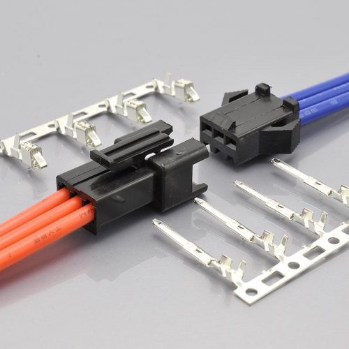
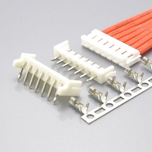
Quick answer: Molex DuraClik is a 2.00mm-pitch, single-row, SMT wire-to-board connector system with an inner positive lock and an audible click, rated 3.0A max, 125V max, 10mΩ max contact resistance, 500V AC withstanding and 1000MΩ min insulation resistance, over 2 to 15 circuits. Its terminal retention depends entirely on which of three variants you specify: 9.8N (Standard), 20N (TPA) or 50N (ISL) — and the operating range widens from −40 to +105°C to −40 to +125°C on the two retainer versions. The KONNRA KR2017 is the cross-reference equivalent for the TPA branch.
Two things decide whether this replacement works, and the first one is a number that appears on two KONNRA documents with two different values.
The first: the product page says 100N. The specification says 40N. KONNRA’s product page states the series offers “a holding force of up to 100N“. KONNRA’s own specification publishes, in section 6.3, a terminal retention force of 15N minimum without the lock and 40N minimum with it, plus a separate 50N minimum lock retention force in section 6.5. And 100N is a real Molex figure — but it is the board retention of the wide solder tabs (100N per 2 nails, tested to SAE automotive vibration standards), not a terminal retention at all. Read as terminal retention, the page’s number is 2.5× the specification’s.
The second: the KR2017’s withdrawal force is published as higher after 30 mating cycles than when new. That is backwards from every other series in this catalogue, where the aged figure is equal to or lower than the initial one. Section 3 sets out the numbers.
Everything here is taken from Molex’s official DuraClik catalogue and KONNRA’s product specification, product page and component pages, all cited at the end.
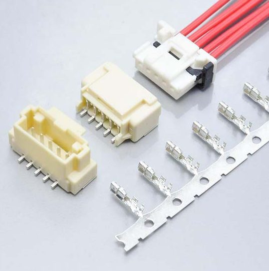
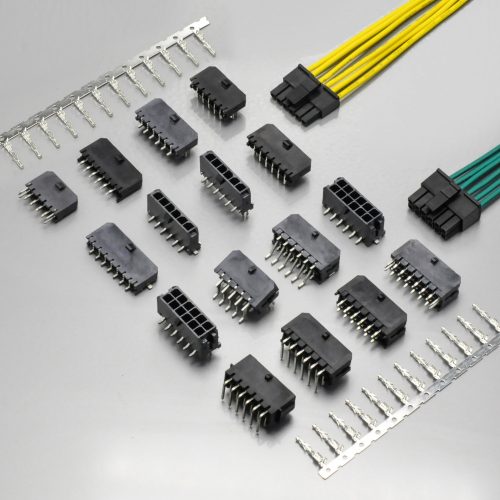
KONNRA KR2017 series DuraClik 2.0 wire-to-board TPA connector, the cross-reference equivalent for the Molex DuraClik system
At a glance
| Item | Molex DuraClik | KONNRA KR2017 |
|---|---|---|
| Pitch | 2.00mm | 2.00mm |
| Rows | Single row | Single row |
| Mounting | SMT (headers) | SMT (both wafers) |
| Circuits | 2 – 15 | see the circuit-count section below |
| Current, max | 3.0A | 3A |
| Voltage, max | 125V | 125V |
| Contact resistance | 10mΩ max | 10mΩ max initial; 20mΩ max after conditioning |
| Withstanding voltage | 500V AC | 500V AC/minute |
| Insulation resistance | 1000MΩ min | 1000MΩ min |
| Operating temperature | −40 to +105°C (Standard) · −40 to +125°C (ISL and TPA) | −40 to +125°C |
| Terminal retention | 9.8N (Standard) · 20N (TPA) · 50N (ISL) | 15N min without lock · 40N min with lock |
| Lock retention | not published separately | 50N min |
| Board retention | 100N per 2 nails | not published |
| Mating confirmation | “Click” sound when mated | large latch with clicking feedback |
| Housing material | PBT (TPA type: PA) | PBT, UL94 V-0 |
| Retainer material | PBT, glass-filled | not published |
| Header material | Polyamide | PA9T, UL94 V-0 |
| Terminal contact | Phosphor bronze | Phosphor bronze |
| Header pin | Copper alloy | Phosphor bronze |
| Plating | Contact area tin or gold; solder tail tin; underplating nickel | Tin over nickel only |
| Packaging | Emboss reel tape | not published |
| RoHS / Low-Halogen | RoHS yes; Low-Halogen | RoHS compliant |
| Agency | not listed in the catalogue | UL E482542 / LV 214 & USCAR-2 |
Four rows in that table need a note before you build on them.
The retention row is the whole story of this comparison and it is covered in its own section below. The short version: Molex publishes three retention grades and KONNRA publishes two additional figures plus a lock strength — and the KONNRA page quotes a number that belongs to a different measurement entirely.
The plating row is a genuine gap, not a rounding. Molex offers the contact area in tin or gold, and its ordering tables carry gold-plated part numbers (560124-0131 terminal, 560020-0230 vertical header, 502352-0210 right-angle header). Every KONNRA document for this series specifies tin only — the specification’s material table lists “Tin Plated Over Nickel” for the terminal and “Matte-tin Plated Over Nickel” for both wafer contacts, with no gold option anywhere. So a gold-plated DuraClik design has no documented KR2017 equivalent. See the plating section.
The header-pin row is not a conflict, and it is worth being precise about why. Molex calls the header pin “Copper Alloy“; KONNRA calls it “Phosphor Bronze“. Phosphor bronze is a copper alloy, so the specific callout sits inside the general one rather than contradicting it. KONNRA is simply more specific than Molex. That is the opposite of the situation on some other series in this catalogue, where the replacement names a different alloy family than the original.
The agency row runs the other way. Molex’s DuraClik catalogue lists RoHS and Low-Halogen status but no UL or automotive file. KONNRA lists UL E482542 alongside LV 214 and USCAR-2 on all four component pages. Those are automotive-qualification standards, and for an automotive programme they are the kind of claim that needs to be verified against a certificate rather than a web page — but it is notable that the replacement publishes more agency data than the original’s own summary sheet.
The 100N claim against the 40N specification
This is the most consequential documentation finding in this comparison, because both figures are real, both are published, and they measure different things.
What the KONNRA product page says:
“Its automotive-grade design integrates ISL technology, inertial locking mechanism, and a holding force of up to 100N to ensure a robust and safe connection.”
What KONNRA’s own specification says:
| Item | Section | Published value |
|---|---|---|
| Terminal / housing retention, without lock | 6.3 | 1.53 kgf (15 N) min |
| Terminal / housing retention, with lock | 6.3 | 4.08 kgf (40 N) min |
| Lock retention force | 6.5 | 5.1 kgf (50 N) min |
| Pin retention force | 6.4 | 1.5 kgf (14.7 N) min |
And what 100N actually is. In Molex’s DuraClik catalogue, 100N appears in exactly one place: the wide solder tabs that anchor the header to the PCB, described as “secure PCB retention that can withstand upward pull force of 100N (10kgf) to meet automotive anti-vibration requirements”, and noted as “100N per 2 nails“.
| Measurement | Molex figure | KONNRA figure | What it measures |
|---|---|---|---|
| Board retention (solder tabs to PCB) | 100N per 2 nails | not published | How hard it is to rip the header off the board |
| Terminal retention (terminal in housing) | 9.8N / 20N / 50N by variant | 15N / 40N | How hard it is to pull a wire out of the housing |
| Lock retention (mating lock strength) | not published separately | 50N | How hard it is to pull the mated pair apart |
So the 100N on the KONNRA page belongs to the first row and the KR2017’s retention specification belongs to the second. They are different interfaces, measured in different directions, failing in different ways. A designer who reads “holding force of up to 100N” as a terminal retention figure is over-estimating by a factor of 2.5 against KONNRA’s own 40N with-lock figure, and by 6.7 against KONNRA’s own 15N no-lock figure.
How the KR2017 actually compares on terminal retention:
| Variant | Molex terminal retention | KR2017 equivalent retention | Difference |
|---|---|---|---|
| Molex Standard (502351) | 9.8N | 15N (no lock) | KR2017 is 53% higher |
| Molex TPA (505151) | 20N | 15N (no lock) | KR2017 is 25% lower |
| Molex ISL (560123) | 50N | 40N (with lock) | KR2017 is 20% lower |
The honest reading: the KR2017 sits between Molex’s grades. It beats the Standard version comfortably, falls 25% short of the TPA grade it is nominally a replacement for when the lock is not engaged, and falls 20% short of the ISL grade when it is. It also publishes a 50N lock retention force that has no direct counterpart in the Molex summary — that is the force to separate the mated connector, which is the number that governs accidental disconnection in a vibrating harness.
None of that makes the part unsuitable. It makes the published marketing number unusable for engineering, and it means the figure to quote in a design review is the one in section 6.3, not the one on the page.
Why the “with lock” and “without lock” distinction matters more than it looks
The 15N and 40N figures are not a tolerance band. They measure the same joint with the secondary lock engaged and not engaged, and they differ by a factor of 2.7.
That is a large difference to hang on whether a small plastic part has been seated. In practice it means the retention capability of the connector is only realised if the lock is correctly installed — and a lock that looks seated but is not gives you 15N, not 40N. KONNRA’s page emphasises exactly this failure mode in its own description of why the series exists, referring to “the risk of incomplete mating of the connectors, which in turn may affect the performance of the final product”, and the TPA retainer’s purpose is to make that condition detectable.
So the practical check is not “does it have a lock” but “how is lock seating verified at assembly”. If your process relies on the mating click alone, note that the click confirms the mating is complete, not that the retainer is seated — those are two separate operations with the same audible feedback claim.
“Molex DuraClik” is three retention grades, not one specification
Exactly as with several other families in this catalogue, the headline name covers more than one product. Molex’s DuraClik catalogue prints four product lines, and the three wire-side ones differ in retention and in temperature:
| Molex DuraClik line | Receptacle housing | Terminal | Retainer | Terminal retention | Operating temperature |
|---|---|---|---|---|---|
| Standard | 502351 | 560085 · 56161 | — | 9.8N | −40 to +105°C |
| TPA | 505151 | 505153 · 505487 | 505152 | 20N | −40 to +125°C |
| ISL | 560123 | 560124 | 560125 | 50N | −40 to +125°C |
| Headers | right-angle 502352 · vertical 560020 | — | — | — | — |
Three consequences follow, and each one has caught somebody out.
Retention varies by a factor of five across the family — 9.8N to 50N. “DuraClik retention” is not a number, it is a range, and the variant determines where in that range you land. A design review that says “DuraClik is rated to 50N” is only correct for the ISL version.
The temperature range divides on the same line, and it is a 20°C difference. The Standard version is rated −40 to +105°C; the ISL and TPA versions reach −40 to +125°C. So the family’s headline 125°C figure applies only to the two retainer versions. The catalogue states this explicitly — “Operating temperatures up to 125 degrees C (ISL and TPA versions)” — and it is the sort of qualifier that gets dropped when a requirement is copied between documents.
The three lines use different housing materials. The catalogue says “Housings: PBT (TPA type: PA)”. So the TPA housing — the variant the KR2017 replaces — is called out as PA, not PBT, in the original’s own data.
⚠️ And that is where a real question sits for this cross-reference. KONNRA’s specification and its housing component page both state the KR2017 housing as PBT UL94 V-0, with no PA option. If Molex’s TPA housing is genuinely PA while the KR2017 equivalent is PBT, the materials differ on the exact variant being crossed. This is worth raising with the supplier before qualification rather than assuming, because a PBT/PA swap changes moisture uptake and dimensional behaviour.
Which line does the KR2017 replace? Its own naming answers this: KONNRA calls it the “KR2017 Series Duraclik 2.0 Wire to Board TPA Connector”, and its four components map as follows:
| KONNRA component | Molex part it names |
|---|---|
| Housing | 560123 Series |
| Terminal | 560124 Series |
| Straight SMT wafer | 560020 Series |
| Right angle SMT wafer | 502352 Series |
⚠️ Note the mismatch in that table, because it is not a typo on my part. The housing page names 560123, and in Molex’s own catalogue 560123 is the ISL receptacle housing, not the TPA one (the TPA housing is 505151). Meanwhile KONNRA’s product name says TPA, and its own specification lists the housing alongside a lock — and the second housing part number it publishes maps to 560125, which Molex calls the ISL retainer.
So the KR2017 names the TPA variant but cross-references ISL part numbers. Both are 2.00mm 125°C retainer systems and they intermate within the family, so this may be a deliberate choice rather than an error — but it means a designer holding an ISL design (560123/560124/560125) is being pointed at the same KONNRA parts as a designer holding a TPA design (505151/505153/505487/505152). Those two Molex designs have different retention figures (50N against 20N), and the KONNRA part cannot be both. Take the cross-reference from the Molex part number you actually have, and confirm it in writing.
The circuit count has four different answers in KONNRA’s own documents
This is a short section because the finding is simply this: there is no single answer to “how many circuits does this series come in”, and the four published answers are all different.
| Source | Circuits as published |
|---|---|
| Product page, At a glance table | 2-14pin |
| Product page, Overview prose (stated twice) | “supporting 2 to 15 circuits in a single row arrangement” |
| All four component pages, Number of Positions | 2P~16P |
| Component cross-reference tables | 2 through 12, plus 14 — 13 and 15 absent |
| Molex, official catalogue | “Available now in 2-15 circuits“ |
Four different ranges across five sources, and the widest one (2P~16P) is on the pages a buyer would use to configure an order.
Two things make this more than a cosmetic problem.
The cross-reference tables — the only place a specific KONNRA part number is tied to a specific Molex part number — stop at 12 and then jump to 14. The straight wafer page lists C2017VS11411M0101RA against 560020-1420 for 14 circuits, and nothing against 560020-1320 or 560020-1520. So the two sizes either side of that jump have no published cross-reference at all, even though Molex publishes both (560020-1320 and 560020-1520 exist in Molex’s own ordering table, as do 502352-1300 and 502352-1500).
And the top of the range is where the disagreement is sharpest. Molex’s catalogue says the family runs to 15 circuits. The KONNRA product page’s table says 14, its prose says 15, and its component pages say 16. If you need a 15- or 16-way connector, this cross-reference is unresolved and has to be confirmed before you quote. If you need 13, the Molex part exists and the KONNRA cross-reference does not.
The practical guidance is the same as everywhere else in this series: configure from a part number, not from a range. Ask for the specific circuit count against the specific Molex number and get it confirmed.
The force table: a withdrawal force that goes up after 30 cycles
This is the most unusual table I have seen in this catalogue, and it is worth reading carefully because the anomaly runs the “wrong” way.
Section 8.0 publishes insertion and withdrawal force for every circuit count from 2 to 15, at initial and after 30 mating cycles. Units are kgf.
| Circuits | 2 | 3 | 4 | 5 | 6 | 7 | 8 | 9 | 10 | 11 | 12 | 13 | 14 | 15 |
|---|---|---|---|---|---|---|---|---|---|---|---|---|---|---|
| I.F. max | 3.6 | 4.4 | 5.2 | 6.0 | 6.6 | 7.2 | 7.8 | 8.4 | 9.0 | 9.6 | 10.1 | 10.8 | 11.4 | 12.0 |
| R.F. min, initial | 0.10 | 0.15 | 0.20 | 0.29 | 0.36 | 0.40 | 0.43 | 0.48 | 0.54 | 0.59 | 0.65 | 0.70 | 0.76 | 0.81 |
| R.F. min, after 30 cycles | 0.10 | 0.21 | 0.33 | 0.38 | 0.43 | 0.47 | 0.51 | 0.55 | 0.59 | 0.63 | 0.67 | 0.73 | 0.80 | 0.86 |
The withdrawal force is published as higher after cycling — at thirteen of the fourteen sizes
Subtract the initial column from the after-30-cycles column:
| Circuits | 2 | 3 | 4 | 5 | 6 | 7 | 8 | 9 | 10 | 11 | 12 | 13 | 14 | 15 |
|---|---|---|---|---|---|---|---|---|---|---|---|---|---|---|
| Change after 30 cycles | 0.00 | +0.06 | +0.13 | +0.09 | +0.07 | +0.07 | +0.08 | +0.07 | +0.05 | +0.04 | +0.02 | +0.03 | +0.04 | +0.05 |
Thirteen sizes are higher, one is unchanged, and none is lower. (Only the 2-circuit row is level, at 0.10 against 0.10.)
This is backwards, and it is backwards in a specific way. Connector retention after repeated mating is expected to stay level or to fall as the contact surfaces wear and the normal force relaxes. Depleting and then increasing is not a mechanism — a part does not grip harder for having been mated thirty times. And this supplier’s own other series publish the opposite: the wire-to-wire and wire-to-board siblings in the same catalogue publish a constant reduction after 30 cycles (0.10 kgf and 0.05 kgf respectively at every size), and a third publishes the two columns as identical.
The pattern of the increments points at the explanation. They are small, they are erratic rather than monotonic (+0.06, +0.13, +0.09, +0.07, +0.07, +0.08, +0.07, +0.05, +0.04, +0.02, +0.03, +0.04, +0.05), and they are all inside the rounding resolution of the printed values. That is what you would expect if the two columns are independent roundings of measurements that were actually very close to each other, rather than one column being derived from the other. Under that reading the table is not claiming that cycling helps — it is claiming that the measurement could not resolve the difference, and the rounding happened to fall on the high side.
I am labelling that as the likely explanation rather than a fact, because the specification does not say. But the practical consequence is explicit either way:
Do not use the after-30-cycles column as a de-rated design value, because it is not a de-rating. For a conservative design figure, use the initial column as the floor. If you need to know what the retention actually is after 30 matings, it has to be measured — and the question to put to the supplier is whether that column was measured independently or transcribed.
Neither column reduces to a clean law, which is itself worth knowing
The sibling series in this catalogue publish force tables that reduce exactly to linear relations. This one does not, and the irregularities are specific enough to list.
The insertion-force column changes slope partway through. From 2 to 5 circuits the steps are +0.8 per position (3.6 → 4.4 → 5.2 → 6.0); from 5 to 11 they are +0.6 per position (6.0 → 6.6 → 7.2 → 7.8 → 8.4 → 9.0 → 9.6). Then the pattern breaks again with +0.5 from 11 to 12 and +0.7 from 12 to 13, before settling back to +0.6 for the last two steps.
So there is no single insertion-force coefficient for this series. A step of 0.8/position at the small sizes and 0.6/position in the middle is a 33% change in the per-contact friction term, and the +0.5/+0.7 pair around 12 circuits fits neither.
The initial withdrawal-force column has one clear discontinuity. The steps run +0.05, +0.05, +0.09, +0.07, +0.04, +0.03, then settle into an alternating +0.05/+0.06 rhythm to the end. The +0.09 step from 4 to 5 circuits is roughly double its neighbours, which is the signature of a single-cell error or of a different geometry at that size.
What this means in practice: interpolation between published sizes is safe in the sibling series because the relations are exact, but here it is not. For a circuit count you have not measured, take the published row for that count rather than computing it. And if you are using the 4-to-5 step or the 11-to-13 region, verify those rows specifically.
The other force figures
| Item | Specification section | Value |
|---|---|---|
| Insertion & withdrawal rate | 6.1 | 25.4 ± 3 mm/minute, excluding plastic detents |
| Terminal insertion force | 6.2 | 1.0 kgf (9.8 N) max |
| Terminal / housing retention, no lock | 6.3 | 1.53 kgf (15 N) min |
| Terminal / housing retention, with lock | 6.3 | 4.08 kgf (40 N) min |
| Pin retention force | 6.4 | 1.5 kgf (14.7 N) min |
| Lock retention force | 6.5 | 5.1 kgf (50 N) min |
Two notes on that block.
Section 6.1 excludes the plastic detents from the force measurement, so the published insertion and withdrawal figures describe the contact system alone. The latch contribution — which is what an operator actually feels — is additional and is not published. Size fixtures and manual-insertion tasks with margin on top of the table.
And section 6.4 has the same translation defect this supplier’s specification carries on other series: the Chinese text describes the pin being pulled out of the wafer while the English in the same cell reads “Apply axial push force”. The item measures retention, so pull-out is the sensible reading — but if you are writing a test procedure from the document, specify the direction yourself rather than copying the English. This is the third consecutive series from this supplier with that same defect in the same clause, which makes it a template problem rather than a one-off.
Crimp and terminal data
The crimp table is different in shape from its siblings: it has two parallel columns for two wire standards covering nominally the same conductor size, and it specifies crimp heights as ranges rather than as nominals with tolerances.
| 0.35 mm² | 22 AWG | |
|---|---|---|
| ① Conductor crimp width | 1.35 max | 1.35 max |
| ① Conductor crimp height | 0.75 – 0.83 | 0.70 – 0.78 |
| ② Insulation crimp width | 1.55 max | 1.55 max |
| ② Insulation crimp height | 1.40 max | 1.40 max |
| Crimp strength, min | 5.0 kgf | 4.54 kgf |
| Stripping | 1.8 – 2.1 mm | 1.8 – 2.1 mm |
Why two columns for one conductor size. 0.35mm² and 22 AWG describe approximately the same cross-section, but they are different wire standards — metric automotive cable such as ISO FLRY-A against AWG-specified cable — and the two differ in stranding and insulation, which is why the crimp settings differ. The setting for one is not valid for the other.
And the strength requirement differs between them: 5.0 kgf for the 0.35mm² wire against 4.54 kgf for 22 AWG. That is a 10% difference in the pull-out requirement for nominally the same copper, which again reflects the different constructions rather than an inconsistency. The 5.0 kgf figure is the highest crimp-strength requirement in this supplier’s catalogue — higher than any of the sibling 2.0mm series — which is consistent with the automotive intent of this part.
The crimp heights are given as windows, not as nominal ± tolerance. 0.75–0.83 is an 0.08mm band and 0.70–0.78 is the same band, shifted down by 0.05. This is a different convention from the sibling series, which publish a nominal with a ± tolerance, and it is arguably the more useful form for a crimp-tool specification because it states the acceptance window directly instead of leaving you to compute it.
Insulation crimp height is specified as a single maximum, 1.40mm, for both columns — not a window and not a target. That is a ceiling, so any setting that stays under it satisfies the specification.
The stripping window is 1.8 to 2.1 mm — a 0.3mm band, the narrowest in this catalogue. For comparison, the sibling series publish 0.5mm, 0.6mm and 0.7mm windows. A strip setting carried over from another series will very likely fall outside this one, so set it from this table rather than reusing a known-good value.
Where the two systems match
On the electrical specification this is the closest match in this series of articles, and it is worth stating plainly because the same comparison has come out twice the other way on sibling parts.
| Parameter | Molex DuraClik | KONNRA KR2017 | Match |
|---|---|---|---|
| Pitch | 2.00mm | 2.00mm | Exact |
| Rows | Single row | Single row | Exact |
| Mounting | SMT | SMT | Exact |
| Current, max | 3.0A | 3A | Exact |
| Voltage, max | 125V | 125V | Exact |
| Contact resistance | 10mΩ max | 10mΩ max | Exact |
| Withstanding voltage | 500V AC | 500V AC/minute | Exact |
| Insulation resistance | 1000MΩ min | 1000MΩ min | Exact |
| Terminal contact material | Phosphor bronze | Phosphor bronze | Exact |
| Mating confirmation | “Click” sound when mated | Large latch, clicking feedback | Equivalent |
| Lock design | Inner positive lock | Safety locking device | Equivalent |
| RoHS | RoHS yes | RoHS compliant | Both compliant |
All five headline electrical ratings match exactly, including contact resistance at 10mΩ. On two sibling series in this catalogue the replacement’s contact-resistance limit is double the original’s; here it is the same figure, measured on the same dry-circuit basis (EIA-364-23C, 20mV max, 100mA max). That is the strongest single point in this comparison and it should carry real weight in a design review.
Where the KR2017 goes further, it is worth noting as well. Molex’s two-page DuraClik catalogue publishes a contact-resistance limit of 10mΩ with no post-conditioning figure. KONNRA publishes both — 10mΩ initial and 20mΩ after environmental testing — and the second one is the number a qualification engineer actually needs.
And where it matches on material, note the one asymmetry. Molex names the terminal contact as phosphor bronze and the header pin as “Copper Alloy”. KONNRA names both as phosphor bronze. Since phosphor bronze is a copper alloy, the KR2017’s specific callout is consistent with Molex’s general one — but if your design has a reason to care which copper alloy is on the board side, Molex has not told you what theirs is either, and the question goes to both suppliers.
Where the two systems differ
| Parameter | Molex DuraClik | KONNRA KR2017 | Nature of the difference |
|---|---|---|---|
| Plating options | Contact area tin or gold | Tin only | Gold has no equivalent |
| Wire range | AVSS 0.3mm² or ISO FLRY-A 0.35mm² | 0.35mm² / 22 AWG only | 0.3mm² not covered |
| Terminal retention | 9.8N / 20N / 50N by variant | 15N / 40N | Between the grades |
| Operating temperature, Standard variant | −40 to +105°C | −40 to +125°C | KR2017 warmer |
| Housing material, TPA variant | PA | PBT | Different polymer |
| Retainer material | PBT, glass-filled | not published | Gap |
| Circuits | 2–15 | 2–14 / 2–15 / 2–16 per document, and 2–12 plus 14 in the cross-reference tables | Four answers published |
| Board retention | 100N per 2 nails | not published | Gap |
| Packaging | Emboss reel tape | not published | Gap |
| Low-Halogen | Low-Halogen | not published | Gap |
| Agency | not listed in the catalogue | UL E482542 / LV 214 / USCAR-2 | KR2017 publishes more |
| Colour | Natural / Black (ISL housing white; TPA black; retainer gray) | Natural / Black | Narrower choice |
Three of those rows deserve more than a table cell.
Plating: gold is available on the original and not on the replacement
This is the cleanest scope gap in the comparison, and it is easy to miss because the KR2017’s plating line looks complete.
| Surface | Molex | KONNRA KR2017 |
|---|---|---|
| Contact area | Tin or Gold | Tin |
| Solder tail area | Tin | Tin (wafer solder tab: matte-tin) |
| Underplating | Nickel | Nickel |
Molex offers the contact area in either finish, and its ordering tables carry gold-plated part numbers throughout the family — 560124-0131 for the ISL terminal, 560020-0230 and 560020-0330 for vertical headers, 502352-0210 and 502352-0310 for right-angle headers. KONNRA’s specification lists “Tin Plated Over Nickel” for the terminal and “Matte-tin Plated Over Nickel” for both wafer contacts, and no gold option appears anywhere in the KR2017 documentation — not in the specification’s material table, not on the product page, not on any of the four component pages.
So a gold-plated DuraClik design has no documented KR2017 equivalent. That matters where the gold was specified for a reason — higher durability across repeated mating cycles, which is exactly what Molex’s catalogue cites as the reason for offering it (“Gold-plated terminal option: higher durability for repeat mating cycling”). If your design is gold on both sides, this is a stop condition rather than a substitution.
Note also that the KONNRA cross-reference lists only the tin terminal (560124-0101); the gold 560124-0131 is not in the table at all. So the gap is consistent across every KONNRA document rather than being an omission on one page.
The wire range: Molex’s 0.3mm² case is not covered
Molex specifies its ISL terminal for two wire types, and KONNRA documents one.
| Molex 560124 terminal | KONNRA KR2017 | |
|---|---|---|
| Wire type 1 | AVSS 0.3mm² | — |
| Wire type 2 | ISO FLRY-A 0.35mm² | 0.35mm², AWG 22# |
| Insulation O.D. | not stated on the summary sheet | 1.4mm max |
Molex’s ordering table names both AVSS 0.3mm² and ISO FLRY-A 0.35mm² as valid wire for the 560124 terminal; KONNRA’s specification names 0.35mm² and AWG 22#. The 0.35mm² / ISO FLRY-A case is covered. The AVSS 0.3mm² case is not — and AVSS is the common Japanese automotive wire designation, so this is a realistic design condition rather than a corner case.
The corresponding crimp settings differ too: KONNRA publishes its own column for 0.35mm² and a separate one for 22 AWG, which is the right way to handle two wire standards — but there is no third column for 0.3mm². If you are running AVSS 0.3mm², the crimp specification does not exist and would need to be developed.
One further detail worth flagging, because it is a labelling problem rather than a value problem: the specification’s section 4.0 puts the conductor size and the insulation diameter under a single heading reading “Applicable wire insulation O.D”, and then gives “0.35mm², AWG 22#” followed by a separate “Insulation O.D. 1.4mm (Max.)”. The heading describes one quantity and the row carries two different ones. Read the values, not the label: conductor 0.35mm² / 22 AWG, insulation outside diameter ≤1.4mm.
Scope: which DuraClik variants the KR2017 does and does not replace
Molex’s DuraClik family is four product lines covering twelve significant part series. The KR2017 is one series with four components. The overlap is real but partial.
| Molex DuraClik line | Molex parts | KR2017 equivalent |
|---|---|---|
| Standard | 502351 housing · 560085 and 56161 terminals | No |
| ISL | 560123 housing · 560124 terminal · 560125 retainer | Named by the KR2017 cross-reference |
| TPA | 505151 housing · 505152 retainer · 505153 and 505487 terminals | Named by the KR2017 product name |
| Headers | 502352 right angle · 560020 vertical | Yes — both wafers |
The headers are covered cleanly and the wire side is ambiguous. The two wafer cross-references are unambiguous — straight wafer to 560020, right angle wafer to 502352 — and both are the only header families Molex makes. But the housing and terminal point at ISL part numbers (560123, 560124) while the product name and the lock arrangement say TPA, and those two lines have different retention (50N against 20N) and use different housing polymers (the catalogue says the ISL housing is PBT-based and the TPA type is PA).
So the statement “KR2017 replaces DuraClik” is too broad to act on. The accurate statement is: the KR2017 replaces the two DuraClik SMT header families, and provides a wire-side equivalent for the retainer variants — with the retention grade to be confirmed against the Molex part number you actually hold. The Standard line (502351 / 560085 / 56161) is not offered at all, and it is the line with the widest circuit range in Molex’s ordering table (2 through 15).
Materials and plating, component by component
| Component | Base material | Plating | Colour |
|---|---|---|---|
| Housing and lock | PBT, UL94 V-0 | — | Natural / Black |
| Terminal | Phosphor bronze | Tin over nickel | — |
| Wafer base (both SMT types) | PA9T, UL94 V-0 | — | Natural / Black |
| Wafer contact (both) | Phosphor bronze | Matte-tin over nickel | — |
| Wafer solder tab (both) | Brass | Matte-tin over nickel | — |
Three things are worth drawing out.
The housing and the wafers use different polymers, and that is deliberate. The housing is PBT; the wafer base is PA9T, a high-temperature polyamide. The wafer goes through the SMT reflow oven while the housing never does, so the wafer needs the higher-temperature material and the housing does not. Molex makes the same split in the opposite direction of specificity — its headers are simply “Polyamide” and its housings “PBT (TPA type: PA)” — so both manufacturers are putting a polyamide on the board side and a PBT-family material on the wire side. KONNRA names the grade; Molex does not.
The solder tab is brass, not phosphor bronze. Both wafers carry a brass solder tab plated matte-tin over nickel, separate from the phosphor bronze contact. Molex lists “Reinforcement: copper alloy, tin-plated” for its SMT headers, which is the same functional element. It is a small point but it is the part that carries the 100N board-retention load described earlier, so it is worth knowing which material is taking that force.
And the mating pair is phosphor bronze against phosphor bronze on both sides. The terminal contact and the wafer contact are both phosphor bronze in KONNRA’s specification, while Molex names phosphor bronze for the terminal contact and “Copper Alloy” for the header pin. So the KR2017 is specific where the original is general — the reverse of the usual pattern in this comparison series, and a point in the KR2017’s favour on documentation completeness.
The environmental programme
Eleven tests, all referenced to EIA standards. As on the adjacent series in this catalogue — and unlike one earlier one — the contact-resistance limit is identical in every test that states one.
| Test | Condition | Reference | Contact resistance limit |
|---|---|---|---|
| Durability | 30 mating cycles at ≤ 10 cycles/minute | EIA-364-09C | 20mΩ max |
| Temperature rise | At rated current load | EIA-364-70B | (30°C max instead) |
| Vibration | 1.5mm P-P, 10~55~10 Hz in 1 minute, 2 hours in each of X, Y and Z | EIA-364-28B | 20mΩ max |
| Shock | 490 m/s² (50g), 3 strokes in each of X.Y.Z | EIA-364-27B | 20mΩ max |
| Heat resistance | 105 ± 2°C for 96 hours | EIA-364-17B | 20mΩ max |
| Cold resistance | −40 ± 2°C for 96 hours | EIA-364-59 | 20mΩ max |
| Humidity | 40 ± 2°C at 90–95% RH for 96 hours | EIA-364-31B | 20mΩ max |
| Thermal shock | −40°C 30 min → room temp 5 min → +105°C 30 min → room temp 5 min, 5 cycles | EIA-364-32B | 20mΩ max |
| Salt spray | 35 ± 2°C, 5 ± 1% solution, 24 hours | EIA-364-26B | 20mΩ max |
| Solderability | 3 ± 0.5 seconds at 245 ± 5°C | EIA-364-52 | (95% wetting instead) |
| Solder heat resistance | SMT per profile 9.1; DIP per profile 9.2 | EIA-364-56D (SMT) / EIA-364-71B (DIP) | (no damage / N/A) |
Eight of the eleven tests state a contact-resistance limit, and all eight allow exactly 20mΩ max. The initial limit is 10mΩ, so the programme permits an exact doubling after any conditioning, uniformly.
This is worth a sentence of comparison rather than just a tick. Molex’s DuraClik catalogue publishes 10mΩ max as its contact resistance and no post-conditioning figure at all in the summary sheet. So the KR2017 documents something the original’s summary does not — the aged limit, which is the figure a qualification plan needs. The trade is that the KR2017’s initial figure equals the original’s and its aged figure doubles from there, so if your budget was built on Molex’s 10mΩ as a life-of-part number rather than an as-supplied number, that assumption needs re-checking.
Beyond the table:
| Result | Published limit |
|---|---|
| Temperature rise at rated current | 30°C max |
| Insulation resistance, initial | 1000MΩ min |
| Insulation resistance, after humidity | 100MΩ min |
| Discontinuity under vibration and shock | 1 microsecond max |
| Solderability, wetted area | 95% of immersed area free of voids and pin holes |
The humidity test relaxes insulation resistance by a factor of ten — 1000MΩ min as supplied, 100MΩ min after 96 hours at 90–95% relative humidity. In a humid application the number to design against is the one in section 7.7, not the 1000MΩ that the product page and all four component pages quote.
A DIP row marked not-applicable, and a wave profile that applies to nothing
Two details in section 7.11 are worth catching because they confirm what this series is.
Section 7.11 splits solder-heat resistance by mounting type and then marks the DIP row “N/A”. The SMT row requires compliance with the reflow profile (9.1) to EIA-364-56D; the DIP row references the wave profile (9.2) to EIA-364-71B and its requirement column reads N/A.
That is correct, and it is the specification telling you something useful: there is no DIP product in this series. Both wafers are surface-mount — straight SMT and right-angle SMT — so the through-hole row does not apply and the document says so rather than leaving it blank.
But section 9.2 still publishes a full wave-soldering profile — 3 to 5 seconds at 250°C max peak, 60 to 150 seconds at a minimum of 217°C, preheat 150 to 180°C — for a product the series does not make. A reader skimming the temperature profiles for a through-hole process will find one, and it does not correspond to anything in the KR2017 range. The relevant profile for this series is 9.1: 5 to 10 seconds at a 255°C ±5°C peak, 20 to 40 seconds at a minimum of 230°C, preheat 150 to 200°C.
For reference, the two profiles are copies of the ones published by the adjacent series in this catalogue, which is unsurprising — the same reflow and wave windows apply across the supplier’s SMT and DIP products.
What is not published
| Not published | Where you would expect it |
|---|---|
| A gold plating option | Molex offers the contact area in tin or gold and carries gold part numbers throughout the family. No gold option appears in any KR2017 document. |
| A crimp specification for 0.3mm² AVSS wire | Molex names AVSS 0.3mm² as valid wire for the 560124 terminal. KONNRA publishes columns for 0.35mm² and 22 AWG only. |
| How the after-30-cycles force column was obtained | The column reports a higher withdrawal force than the initial column at thirteen of the fourteen sizes, with erratic increments. The specification does not say whether it was measured independently. |
| A UL- or CSA-rated voltage | The component pages list UL E482542 with LV 214 and USCAR-2 but attach no rated voltage to the listing. The general rating is 125V. |
| A board-retention figure | Molex publishes 100N per 2 nails for its wide solder tabs. KONNRA publishes nothing for the equivalent tab, though its product page quotes the 100N figure in a context that suggests it is a retention specification. |
| Packaging and reel quantity | Molex specifies emboss reel tape. No reel quantity appears in the KR2017 specification or on the component pages. |
| Low-Halogen status | Molex lists Low-Halogen. KONNRA states RoHS compliance but does not address halogen content. |
| Retainer material | Molex specifies its retainer as PBT, glass-filled. KONNRA’s lock appears in the specification grouped with the housing as “PBT UL94 V-0” with no separate callout for a glass-filled grade. |
| Colour choice against the original’s scheme | Molex uses white for the ISL housing, black for the TPA housing and gray for the retainer. KONNRA offers natural/black across the range. |
Two rows there matter more than the others.
The gold gap is a stop condition, not a preference. If a DuraClik design is gold-plated, the KR2017 does not offer a documented equivalent for it, and that is a range limitation rather than a specification difference. Confirm before spending time on the rest of the comparison.
The board-retention gap is the counterpart to the 100N question at the top of this article. Molex publishes an explicit 100N per 2 nails board retention — the whole point of the wide solder tabs on this family. KONNRA’s specification publishes the pin retention (1.5 kgf, i.e. ~14.7N, for a single pin pulled from the wafer) but no aggregate board-retention figure for the solder tabs, even though its product page quotes 100N. So the one number the page leads with is the one number the specification does not support.
How to identify which DuraClik you have
The variant decides the retention and the temperature rating, so identify it first. Molex’s own ordering structure gives you the answer.
Step one: read the housing part number prefix.
| Housing prefix | Molex line | Terminal retention | Operating temperature |
|---|---|---|---|
| 502351 | Standard | 9.8N | −40 to +105°C |
| 505151 | TPA | 20N | −40 to +125°C |
| 560123 | ISL | 50N | −40 to +125°C |
Step two: check whether the design uses a retainer. The TPA line uses 505152 and the ISL line uses 560125; the Standard line has none. If your design has a retainer, the temperature rating is 125°C and the retention grade is 20N or 50N. If it has none, you are in the Standard line at 105°C and 9.8N.
Step three: read the header suffix to get the mounting and orientation.
| Header part form | Orientation | KONNRA wafer |
|---|---|---|
560020-0x20 / -0x30 |
Vertical | Straight SMT wafer |
502352-0x00 / -0x01 |
Right angle | Right angle SMT wafer |
502352-0x10 |
Right angle, gold | No KR2017 equivalent |
The suffix digit after the circuit count carries the finish: on the vertical headers -0x20 is natural tin and -0x30 is natural gold, and on the right-angle headers -0x00 is natural tin, -0x01 is black tin and -0x10 is natural gold. So the finish is readable from the part number, and that is the quickest way to find out whether the gold gap applies to you.
Step four: confirm the circuit count from the part number rather than from any range. Molex publishes 2 through 15; the KONNRA cross-reference tables stop at 12 and jump to 14; the KONNRA component pages claim 2P~16P. Ask for the specific count.

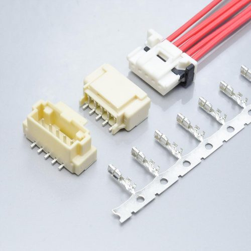
KONNRA KR2017 2.00mm housing with TPA, the cross-reference for the Molex DuraClik receptacle housing
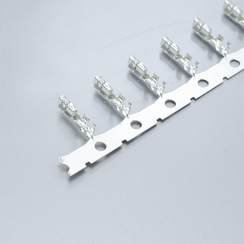
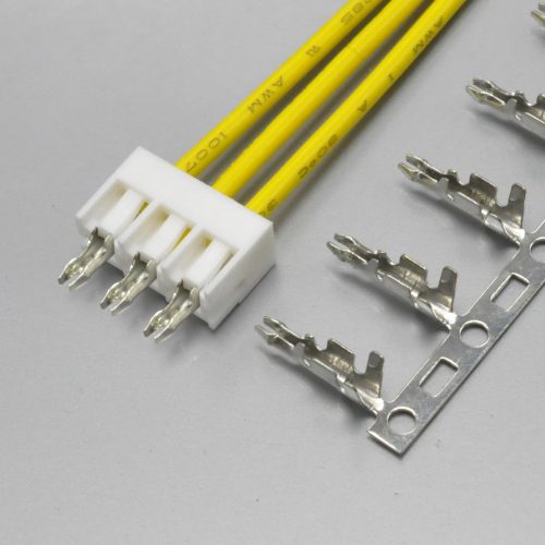
KONNRA KR2017 2.00mm terminal, the cross-reference for the Molex 560124 female terminal
The two board-side options, which are the only two header families Molex makes:
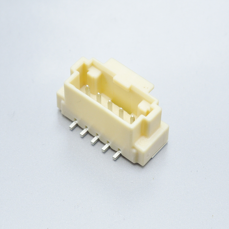
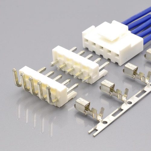
KONNRA KR2017 straight SMT wafer, the cross-reference for the Molex 560020 vertical header
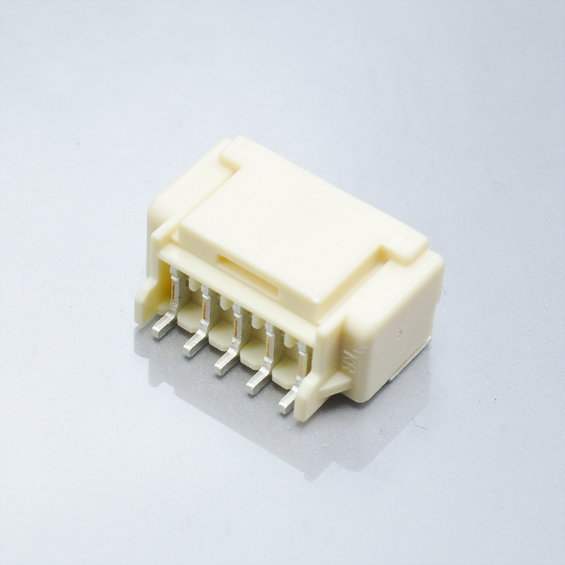
KONNRA KR2017 right angle SMT wafer, the cross-reference for the Molex 502352 right-angle header
Where the KR2017 sits in the 2.00mm class
Within KONNRA’s 2.00mm pitch category, the Series filter enumerates nineteen codes, and four of them are positioned against Molex 2.0mm families:
| KONNRA series | Molex family | Category |
|---|---|---|
| KR2017 | DuraClik | SMT wire-to-board |
| KR2007 | 2.0mm wire-to-wire (51005/51006) | Wire-to-wire |
| KR2000 | MicroBlade | Wire-to-board |
| KR2021 | MINI50 | Wire-to-board |
Three of those four carry the string “mx2.0” in their title on the category page, and they refer to three different Molex families. Only one of them, the KR2007, is the 51005/51006 wire-to-wire system; KR2017 is DuraClik and KR2000 is MicroBlade. “mx2.0” on this site means “Molex 2.00mm pitch”, not any specific Molex family — search on the family name.
And within the family itself, the four lines are worth keeping straight, because the KR2017 covers two of them well and the wire side only partially:
| Molex line | Retention | KR2017 coverage |
|---|---|---|
| Standard | 9.8N at −40~+105°C | Not offered |
| TPA | 20N at −40~+125°C | Named by the KR2017 product name |
| ISL | 50N at −40~+125°C | Named by the KR2017 cross-reference |
| Headers | — | Both wafer types covered |
The clean way to state it: the KR2017 is a DuraClik header replacement and a DuraClik retainer-housing equivalent, not a DuraClik Standard replacement. If your design is on the Standard line, this series is not the answer.
Cross-reference checklist: ten things to verify before you commit
Work through these in order. The first two decide whether the rest applies.
- Establish whether the design is gold-plated. Molex offers the contact area in tin or gold, and its ordering tables carry gold part numbers (
560124-0131,560020-0230,502352-0210). No KR2017 document offers gold. If your design is gold, this is a stop condition. The finish is readable from the part-number suffix, so this takes one line of checking. - Identify which DuraClik line you have, because the retention and temperature depend on it. 502351 is Standard at 9.8N / −40~+105°C; 505151 is TPA at 20N / −40~+125°C; 560123 is ISL at 50N / −40~+125°C. The KONNRA product name says TPA while its cross-reference names ISL parts — those two have different retention, so take the answer from your own Molex part number.
- Use the specification’s retention figures, not the product page’s. Section 6.3 gives 15N min without the lock and 40N min with it; section 6.5 gives a 50N min lock retention force. The page’s “up to 100N” is Molex’s board retention (100N per 2 nails) and measures a different interface. Against Molex’s grades, the KR2017 is 53% above Standard, 25% below TPA and 20% below ISL.
- Confirm the circuit count individually. Molex publishes 2–15; the KONNRA product page’s table says 2-14, its prose says 2-15, its component pages say 2P~16P, and its cross-reference tables list 2–12 plus 14. Sizes 13 and 15 have Molex parts but no KONNRA cross-reference.
- Check your wire standard, not just your gauge. Molex specifies the 560124 terminal for AVSS 0.3mm² or ISO FLRY-A 0.35mm². KONNRA documents 0.35mm² / 22 AWG only. AVSS 0.3mm² has no published KR2017 crimp specification.
- Settle the TPA housing material question. Molex’s catalogue says the TPA-type housing is PA; KONNRA specifies the KR2017 housing as PBT. Confirm which applies before qualification, because a PBT/PA change affects moisture uptake and dimensional behaviour.
- Re-check any contact-resistance budget built on 10mΩ as a life-of-part figure. The KR2017 matches the original at 10mΩ initial — the strongest point in this comparison — but permits 20mΩ after any environmental conditioning, doubling uniformly across all eight tests that state a limit.
- In a humid application, design against 100MΩ, not 1000MΩ. Section 7.7 permits the ten-fold relaxation after 96 hours at 90–95% relative humidity, and the product page and all four component pages quote only the 1000MΩ figure.
- Use the SMT reflow profile (9.1), not the wave profile (9.2). This series is SMT only — section 7.11 marks its DIP row N/A — yet a full wave profile is still published. The applicable window is 5 to 10 seconds at a 255°C ±5°C peak with preheat at 150 to 200°C.
- Do not interpolate the force table, and do not use its after-30-cycles column as a de-rating. The insertion column changes slope from 0.8/position to 0.6/position, and the withdrawal column shows published increases after cycling at thirteen of the fourteen sizes. Take the row you need, and treat the initial column as the conservative floor.
Frequently asked questions
What is the KONNRA KR2017 a replacement for?
The Molex DuraClik 2.00mm SMT wire-to-board system, specifically the two header families (vertical 560020 and right-angle 502352) and the wire-side retainer variants. KONNRA’s four component pages name 560123 (housing), 560124 (terminal), 560020 (straight wafer) and 502352 (right angle wafer). The Standard DuraClik line (502351 housing, 560085/56161 terminals) is not offered.
Why does the product page say 100N when the specification says 40N?
Because they are different measurements. 100N is Molex’s board retention — the wide solder tabs holding the header to the PCB, published as “100N per 2 nails” and tested to SAE automotive vibration standards. 40N is the KR2017’s terminal retention with the lock engaged, published in specification section 6.3 alongside a 15N figure for the same joint without the lock. Every KONNRA document that measures the terminal gives 15N or 40N; only the marketing page gives 100N, and it is quoting the board figure.
How does the retention compare with the original?
Against Molex’s three grades: the KR2017’s 15N no-lock figure is 53% higher than the Standard version’s 9.8N and 25% lower than the TPA version’s 20N; its 40N with-lock figure is 20% lower than the ISL version’s 50N. It also publishes a 50N lock retention force that Molex does not publish separately. The lock matters: engaging it takes the same joint from 15N to 40N, a factor of 2.7.
Is the electrical performance the same?
Yes on all five headline figures — 3.0A, 125V, 10mΩ max contact resistance, 500V AC withstanding and 1000MΩ min insulation resistance are identical to Molex’s published ratings, measured on the same dry-circuit basis. This is the closest electrical match in this comparison series. The difference is that KONNRA additionally publishes a post-conditioning contact-resistance limit of 20mΩ max, which Molex’s summary sheet does not give.
How many circuits does it come in?
Officially, Molex publishes 2 to 15. KONNRA’s own documents disagree with each other and with that: the product page’s table says 2-14, its prose says 2 to 15, the four component pages say 2P~16P, and the cross-reference tables list 2 through 12 plus 14, leaving 13 and 15 without a cross-reference. Confirm the specific count you need rather than working from a range.
Does the KR2017 come with a gold plating option?
No. Every KONNRA document for this series specifies tin — “Tin Plated Over Nickel” for the terminal, “Matte-tin Plated Over Nickel” for the wafer contacts and solder tabs. Molex offers tin or gold in the contact area and carries gold part numbers throughout the family, so a gold-plated DuraClik design has no documented equivalent here.
What wire does the terminal take?
0.35mm² / 22 AWG, with a maximum insulation outside diameter of 1.4mm. Note that Molex specifies its 560124 terminal for two wire types — AVSS 0.3mm² and ISO FLRY-A 0.35mm² — and the 0.3mm² case is not covered by the KR2017 crimp specification. The crimp settings also differ between the 0.35mm² and 22 AWG columns, so use the column matching your wire standard.
Why is the insertion and withdrawal force table irregular?
Because it is. The insertion column steps by 0.8 per position from 2 to 5 circuits and then by 0.6 per position from 5 to 11, with a +0.5 and a +0.7 step breaking the pattern around 12 circuits. The initial withdrawal column has a +0.09 step from 4 to 5 that is roughly double its neighbours. Unlike the sibling series in this catalogue, neither column reduces to a clean linear law, so take the published row for the size you need rather than interpolating.
Why is the withdrawal force higher after 30 cycles?
The specification does not say, and it is worth asking. The after-30-cycles column is higher than the initial column at thirteen of the fourteen sizes (the 2-circuit row is level), with small, erratic increments ranging from 0.00 to +0.13. Retention is not expected to increase with wear, and this supplier’s other series publish equal or reduced figures. The pattern is consistent with the two columns being independent roundings of measurements that were nearly identical — but that is my reading, not a statement in the document.
Does the KR2017 have a through-hole version?
No. Both wafers are surface-mount — straight SMT and right-angle SMT — and section 7.11 of the specification marks its DIP solder-heat row N/A to confirm it. Note that a full wave-soldering profile is nevertheless published in section 9.2, which corresponds to no product in this series. Use the SMT reflow profile in section 9.1.
What is the operating temperature range?
−40 to +125°C across the KR2017 range. On the Molex side this figure applies only to the ISL and TPA variants; the Standard variant is rated −40 to +105°C. So the KR2017’s range matches the retainer versions of the original and exceeds the Standard version by 20°C at the top end.
Which agencies is it listed to?
All four component pages list UL E482542 together with LV 214 and USCAR-2 under an “Industry Standard” field. No rated voltage is attached to the listing, which is the gap to close if your design depends on an agency-recognised voltage. Molex’s DuraClik summary sheet lists RoHS and Low-Halogen status but no UL or automotive file, so KONNRA publishes more agency data than the original’s own catalogue page does.
Why do the component pages name different Molex families than the product name?
Because the product name says TPA (KONNRA calls it the “Duraclik 2.0 Wire to Board TPA Connector”) while the cross-reference tables name ISL part numbers — 560123 is Molex’s ISL receptacle housing and 560125, which the housing page lists as a housing, is Molex’s ISL retainer. Both lines are 2.00mm, 125°C and intermate within the family, so this may be deliberate, but they carry different retention figures — 20N for TPA against 50N for ISL — so the grade has to be confirmed against the Molex part number you actually hold.
Start your cross-reference check
Two facts decide most of this comparison, and both come out of your own documentation in minutes.
- Send the Molex housing part number and the header suffix. The housing prefix tells us whether you are on the Standard, TPA or ISL line — and therefore whether the retention grade is 9.8N, 20N or 50N and whether the temperature rating is 105°C or 125°C. The header suffix tells us the orientation and, crucially, whether the finish is tin or gold — and if it is gold, the answer is that this series does not cover it.
- Send your wire standard, not just the gauge. If you are running AVSS 0.3mm², the KR2017 crimp specification does not exist and that is the end of the comparison. If you are on ISO FLRY-A 0.35mm² or 22 AWG, we can quote to the right column.
Then ask the two questions the documents cannot answer: which housing polymer applies to the TPA-type part (Molex’s catalogue says PA, KONNRA’s says PBT), and whether the after-30-cycles force column was measured or transcribed.
The cross-referenced components are the Housing (H201701xx2401A, replacing the Molex retainer-variant receptacle housing), the Lock (H201701xx0511A, replacing the 560125 ISL retainer), the Terminal (T20170PT0101A, replacing 560124-0101), and the two wafers — Straight SMT (C2017VS1xx11M0101RA, replacing 560020) and Right angle SMT (C2017RS1xx11M0101RA, replacing 502352). All are 2.00mm pitch, single row, 3A, 125V AC/DC, −40°C to +125°C, listed to UL E482542 / LV 214 / USCAR-2, and RoHS compliant.
- View the KONNRA KR2017 DuraClik 2.0 wire-to-board connector series
- Download the KR2017 product specification (PS-KR2017-01)
- Download the KR2017 series drawing
- Send an enquiry to KONNRA
Sources and method
Every figure in this article comes from a manufacturer document and is cited so it can be checked. Where a figure could not be obtained, it is listed as not published rather than estimated.
Molex primary document:
- DuraClik 2.00mm Pitch Wire-to-Board Connectors, SMT, Single Row, Positive Lock — Molex’s official two-page catalogue, distributed by RS (
docs.rs-online.com/6ad2/0900766b814868fc.pdf). Source of: the electrical specification (125V max, 3.0A max, 10 milliohm max contact resistance, 500V AC dielectric withstanding, 1000 megohm min insulation resistance); Contact Retention to Housing — Standard 9.8N, TPA 20N, ISL 50N; Operating Temperature −40 to +105°C (Standard) and −40 to +125°C (ISL and TPA); the wide solder tabs with 100N (10kgf) per 2 nails board retention tested to SAE automotive vibration standards; the inner positive-lock design and the “click” sound when mated; the Independent Secondary Lock providing up to 50N and the Terminal Position Assurance providing up to 20N; the inertia lock on the TPA version; the materials table — Housings PBT (TPA type: PA), Retainers PBT glass-filled, Headers Polyamide, Terminal Contact Phosphor Bronze, Header Pin Copper Alloy, plating tin or gold on the contact area, tin on the solder tail, nickel underplating; the four product lines and their part numbers (Standard 502351 / 560085 / 56161, ISL 560123 / 560124 / 560125, TPA 505151 / 505152 / 505153 / 505487, Headers 502352 and 560020); the ordering tables including the gold-plated part numbers, the AVSS 0.3mm² and ISO FLRY-A 0.35mm² wire callouts, the colour options, and 2-15 circuits; RoHS and Low-Halogen status; and emboss reel tape packaging
KONNRA primary documents:
- Product specification PS-KR2017-01, Revised / Edition A2, dated 2023/5/5, 7 pages —
konnra.com/wp-content/uploads/2023/08/PS-KR2017-01_20230505.pdf. Source of: the part numbers including the terminalT20170PT0101Aand the housing-and-lock pair; the material and plating table by component including PBT UL94 V-0 for the housing and lock, PA9T UL94 V-0 for the wafer base, and matte-tin over nickel on the wafer contact and solder tab; the ratings (125V AC/DC, 3A, −40 to +125°C, 0.35mm² / AWG 22#, insulation O.D. 1.4mm max); sections 5.0 to 7.0 with all eleven environmental and process tests; the uniform 20mΩ post-conditioning limit and the 100MΩ post-humidity insulation resistance; the mechanical figures including terminal retention 15N without lock and 40N with lock in 6.3, pin retention 1.5 kgf in 6.4 and lock retention 5.1 kgf in 6.5; the crimp table with its 0.35mm² and 22 AWG columns; both temperature profiles including the wave profile at 9.2 that applies to no product in this series; the DIP row marked N/A in 7.11; and the section 8.0 insertion and withdrawal force table for 2 to 15 circuits - Product page — source of the “holding force of up to 100N” claim, the
2-14pintable and the “2 to 15 circuits” prose, the material linePBT /UL94/PA9T/Phosphor Bronze, the withstanding voltage of 500V AC, the contact resistance of 10mΩ max, and the “KR2107” typo in the compliance paragraph - The four component pages: housing, terminal, straight SMT wafer, right angle SMT wafer — source of the
2P~16Pposition claim, theE482542/LV 214 & USCAR-2listings, the compatible-series names (560123, 560124, 560020, 502352), and the part-number cross-reference tables covering 2–12 and 14 - Package specification
Package-spec_KR2017-Connector.pdf— published, graphics-based; no figure in this article is quoted from it - Series drawing
KR2017-Series-Drawing_20240726.pdf— published at 845KB; its content is graphics rather than text and could not be extracted, so no figure in this article is quoted from it - 2.00mm pitch category
Method notes:
The force-table findings are direct readings of the specification’s own columns, not inferences. The “change after 30 cycles” row is a row-by-row subtraction of two published columns, and the count of thirteen of the fourteen sizes showing an increase is a count of the sign of those differences. The claim that this is inconsistent with the supplier’s other series is a comparison against those series’ published force tables, which show a constant reduction or an identical pair of columns.
The mapping of KONNRA wafers to Molex header families was verified against Molex’s own ordering tables: 560020 is the vertical header and 502352 the right-angle header, so straight-to-vertical and right-angle-to-right-angle are the correct pairings.
The 100N finding rests on two independently published facts: KONNRA’s page uses the figure as a general holding force, and Molex’s catalogue uses the same 100N figure specifically for board retention at 100N per 2 nails while publishing separate terminal-retention figures of 9.8N, 20N and 50N. The two are not the same measurement, and the specification’s own 40N figure is the terminal-retention value.
The suggestion that the after-30-cycles column results from independent rounding is labelled as a likely explanation rather than a documented fact, because the specification does not state how the column was obtained.
The statement that KONNRA’s header pin callout does not conflict with Molex’s is based on phosphor bronze being a copper alloy; it is presented as a matter of specificity rather than as a material substitution.
Corrections are welcome and will be made. If a figure here disagrees with the current revision of a manufacturer document, the manufacturer document is right and this article should be corrected against it.