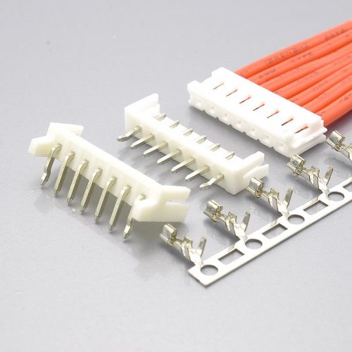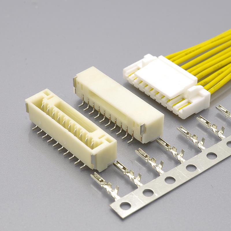
The JST GH connector is a 1.25mm pitch wire-to-board crimp connector with a secure locking mechanism, mounted on the PCB as a surface-mount (SMT) wafer. It is the standard interconnect for compact electronics — flight controllers, cameras, wearables, medical devices, and any design where 1.0mm pitch is too fine to handle and 2.0mm pitch takes up too much board space.
Its reach extends well beyond generic compact electronics. The JST GH 1.25mm connector was adopted as the Pixhawk Connector Standard for the ArduPilot / Dronecode autopilot ecosystem, which is why an enormous share of GPS modules, telemetry radios, rangefinders, and power modules on the market today ship with GH connectors already crimped on.
Despite that ubiquity, the JST GH is rarely documented against its own official JST part numbers in a way that lets engineers cross-reference datasheets, verify specifications, or qualify a second source. Third-party listings contradict each other on basics — wire gauge being the most common casualty — and the official numbering system is seldom explained in one place.
This guide closes that gap. It documents the complete JST GH 1.25 specification system, cross-references it component by component to the KONNRA KR1259 series, and provides the circuit-count, footprint, and application detail needed to specify the connector with confidence.
A note on naming: this part is written and searched in several equivalent forms — JST GH1.25 connector, JST GH 1.25, GH 1.25, and “1.25mm JST connector” all refer to the same 1.25mm pitch JST GH series. This guide uses “JST GH 1.25” throughout for readability, and covers both the official JST GH part numbering and the KONNRA KR1259 cross-reference equivalent.
What Is the JST GH 1.25 Connector?
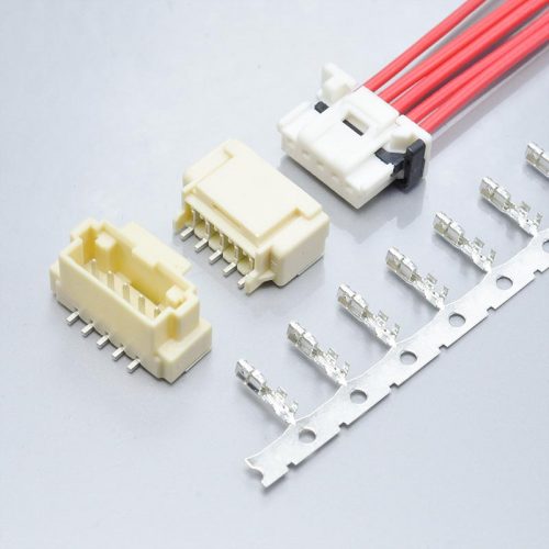
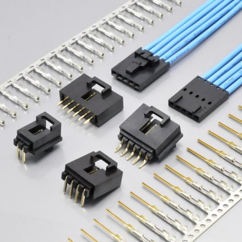
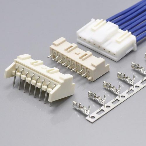
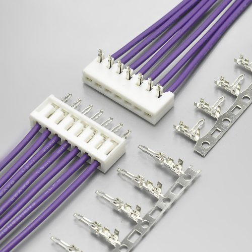
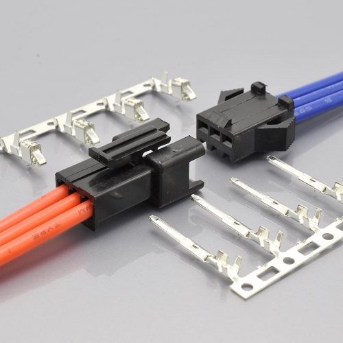
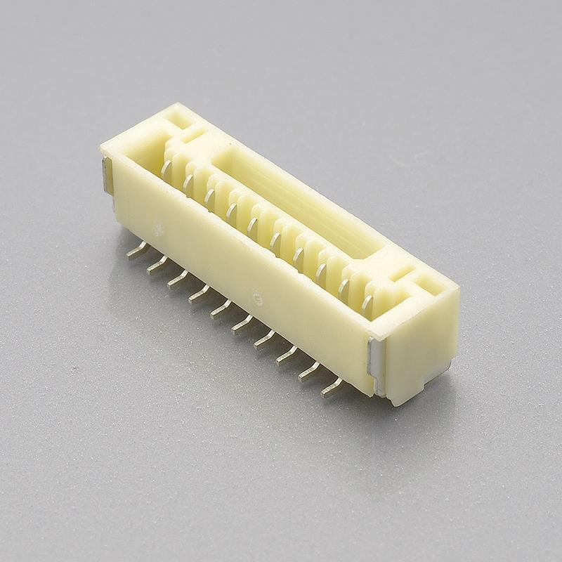
The JST GH is a 1.25mm pitch, single-row, wire-to-board crimp connector system with a positive locking function and SMT PCB mounting. A complete connector set consists of four components:
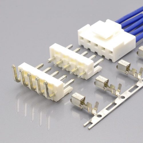
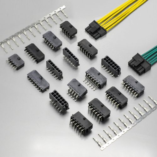
- SMT wafer — PCB-side surface-mount header, straight (180°) or right-angle (90°)
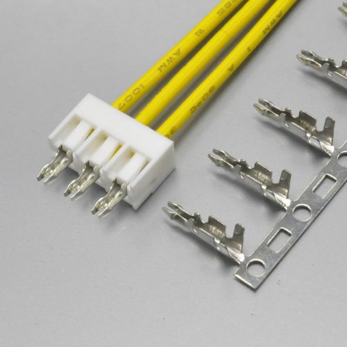
- Housing with lock — wire-side plug with integrated locking latch
- Terminal — crimp contact for AWG #30–#26 wire
- Optional cable assembly — pre-crimped harness built on the above three parts
Key characteristics:
- 1.25mm pitch — sits between the JST SH (1.0mm) and JST ZH (1.5mm), balancing compact size against assemblability
- Single row — 2 to 16 circuits on the KONNRA KR1259
- Secure locking mechanism — the housing latches to the wafer with a positive tactile click, preventing accidental disconnection
- Low insertion force — designed for easy mating in dense assemblies
- SMT mounting — surface-mount wafers only; there is no through-hole version of the GH system
- 1A per contact at 50V AC/DC — rated with AWG #26 wire
- Operating temperature −40°C to +105°C on the KONNRA KR1259 — wider than the −25°C to +85°C range commonly quoted for the JST GH series
- RoHS compliant
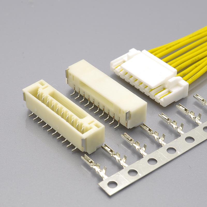
**View the KONNRA KR1259 GH 1.25 Connector with Lock**
JST GH = KONNRA KR1259: The Naming Explained
The GH system carries different names across JST’s own component families and across suppliers, which is where most cross-referencing confusion originates. The table below maps the market name, the JST part families, and the equivalent KONNRA KR1259 component.
| Market Name | JST Part Family | Type | KONNRA Equivalent |
|---|---|---|---|
| JST GH 1.25 | GHR-xxV-S | Wire housing with lock | KR1259 Housing |
| JST GH 1.25 | BM…B-GHS-TBT / SM…B-GHS-TB | SMT wafer (PCB header) | KR1259 SMT straight / right-angle wafer |
| JST GH 1.25 | SSHL-002T-P0.2 | Crimp terminal | KR1259 Terminal |
| JST GH 1.25 | — | Complete pre-crimped cable assembly | KR1259 cable assembly |
The circuit count is embedded directly in the JST part number: GHR-04V-S is the 4-circuit housing, GHR-06V-S is the 6-circuit housing, and so on. Reading the housing part number is therefore the fastest way to confirm which pin count a cable assembly actually is.
Relationship to the rest of the JST lineup: the GH is not a variant of the PH or XH series — it is a separate 1.25mm pitch system with its own housings, wafers, and terminals. It is frequently confused with the JST SH (1.0mm), because the two share a similar appearance and both are used in compact electronics, and with the JST ZH (1.5mm), which shares the SMT mounting concept at a larger pitch. None of the three mate with each other.
Note on mounting style: JST documents the GH as an SMT-mounted system only. KONNRA documents the KR1259 with an SMT straight (180°) wafer and an SMT right-angle (90°) wafer. If your PCB layout assumes a through-hole or DIP footprint, there is no GH equivalent — this is one of the most common cross-reference traps in the 1.25mm class.
JST GH 1.25 / KONNRA KR1259 Specifications
The table below puts the published JST GH specifications alongside the KONNRA KR1259 specifications. Both columns are sourced from manufacturer documentation — not from distributor listings.
| Parameter | JST GH 1.25mm (JST documentation) | KONNRA KR1259 (KONNRA documentation) |
|---|---|---|
| Pitch | 1.25mm | 1.25mm |
| Row configuration | Single row | Single row |
| Connection type | Wire-to-Board | Wire-to-Board |
| Current rating (max) | 1.0A AC/DC (AWG #26) | 1A (1.0A AC/DC using AWG #26) |
| Voltage rating | 50V AC/DC | 50V |
| Contact resistance | 30mΩ Max (initial); 50mΩ Max after environmental testing | 30mΩ Max |
| Insulation resistance | 100MΩ Min | 100MΩ Min |
| Withstanding voltage | — | 500V AC / minute |
| Operating temperature | −25°C to +85°C | −40°C to +105°C |
| Wire size | AWG #30 – #26 (0.05 – 0.13mm²) | AWG #30 – #26 |
| Insulation diameter | 0.8 – 1.0mm | 1.0mm Max |
| Circuits | 2 – 10 in common use | 2 – 16 |
| Housing material | — | PA66 / PBT, UL94 |
| Contact material | — | Phosphor Bronze |
| Contact plating | Tin-plated | Tin / Gold flash over Nickel |
| Mount type | SMT | SMT straight 180°, SMT right-angle 90° |
| Locking | Secure locking mechanism (positive lock) | Locking structure with terminal lock |
| Compliance | RoHS compliant | RoHS compliant |
” — ” indicates the parameter is not stated in the manufacturer documentation reviewed for this guide. Confirm any blank against the current JST GH series datasheet before releasing a drawing.
Specification differences worth verifying before you cross-reference
The JST GH is one of the most frequently mis-specified connectors in compact electronics, mostly because third-party listings propagate each other’s errors. Four points deserve attention during component qualification:
1\. Wire gauge — the single most common error. The JST GH is very widely listed as accepting AWG 28–32 wire. The JST GH terminal (SSHL-002T-P0.2) is documented for 0.05–0.13mm², which is AWG #30–#26, with an insulation diameter of 0.8–1.0mm. AWG 28–32 is the wire range of the JST SH (1.0mm) series, and the two are routinely mixed up. The KONNRA KR1259 is documented as AWG #30–#26, matching the JST GH terminal. If you have a harness drawing that specifies AWG 30 or 32 wire, check compatibility before ordering in volume — a 32 AWG conductor may not crimp reliably in a GH terminal.
2\. Operating temperature. The JST GH series is commonly documented at −25°C to +85°C. The KONNRA KR1259 is rated −40°C to +105°C. Where a design has to survive outdoor use, engine-bay-adjacent installation, or thermal cycling inside a sealed enclosure, that 20°C of extra headroom on both ends is a genuine qualification difference.
3\. Insulation resistance. Official JST documentation states 100MΩ minimum, and the KONNRA KR1259 is documented at the same 100MΩ minimum. Some third-party listings quote 1,000MΩ — a ten-fold difference that appears to be copied from another series. Use the manufacturer figure.
4\. Mounting style. Because the GH is SMT-only, there is no drop-in through-hole option. Confirm whether your board was originally laid out for an SMT pad pattern before you plan a substitution.
JST GH 1.25 vs the Other 1.25mm Pitch Systems
Three connector families dominate the 1.25mm pitch class, and they are not interchangeable with each other despite sharing a pitch. The table below positions them, with the KONNRA cross-reference series for each.
| Feature | JST GH 1.25 | Molex PicoBlade 1.25 | HIROSE DF13 1.25 |
|---|---|---|---|
| Pitch | 1.25mm | 1.25mm | 1.25mm |
| Voltage rating | 50V AC/DC | 125V | 150V |
| Current rating | 1A | 1A | 1A |
| Rows | Single | Single | Single / dual |
| Locking | Secure locking mechanism | Top latch | Friction lock |
| Mount type | SMT | Through-hole and SMT | SMT |
| KONNRA equivalent | KR1259 | KR1250 / KR1251 / KR1252 / KR1253 | KR1256 / KR1258 |
| Best for | Flight controllers, compact IoT, wearables, medical | Sensor and peripheral wiring where 125V headroom is needed | Industrial and instrumentation wiring with dual-row density |
Why the voltage ratings differ so much. All three families are rated 1A per contact, but the voltage rating varies by a factor of three: 50V for the GH, 125V for the PicoBlade, and 150V for the DF13. This is not a marketing difference — it reflects different contact geometries and creepage distances. In battery-powered compact electronics running at 3.3V or 5V, it is irrelevant. In a mains-referenced or higher-voltage measurement front end, it decides which family you are allowed to use.
Why the pitch is not the whole story. Same pitch does not mean same footprint, same mating height, or same retention. A GH housing will not mate with a PicoBlade wafer, and a GH wafer will not accept a PicoBlade housing. The only reliable approach is to cross-reference on the specific part number.
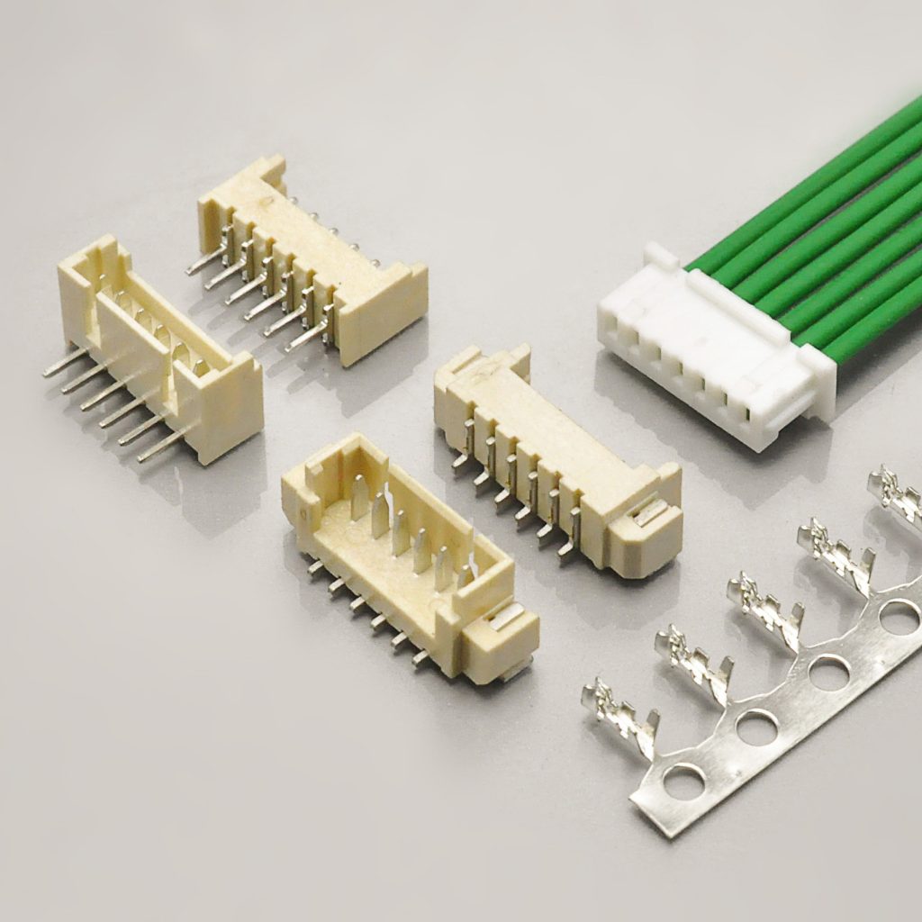
Explore the 1.25mm pitch connector range
Why the JST GH Dominates Drones, Robotics, and Compact IoT
The JST GH 1.25mm connector was adopted as the Pixhawk Connector Standard by the Dronecode and ArduPilot projects, which makes it the de facto interconnect for autopilot peripherals worldwide. Very few connectors in the 1.25mm class can claim a single ecosystem standard behind them, and it is the main reason demand for the GH series is so durable.
In the Pixhawk ecosystem, GH connectors are used for the following port classes:
| Port class | Typical GH pin count | What it carries |
|---|---|---|
| GPS | 6-pin | Power, UART, and I²C for a GPS/compass module |
| TELEM | 6-pin | Power and UART to a telemetry radio |
| I²C | 4-pin | Power and I²C bus to external sensors |
| CAN | 4-pin | Power and CAN bus to peripherals |
| POWER | 6-pin (8-pin on some newer boards) | Power module current and voltage sensing |
If you are building cable assemblies for this ecosystem, the practical implication is that you will be crimping the same three components repeatedly in 4-pin and 6-pin configurations, at volumes where crimp consistency matters more than anything else. That is a manufacturing question, not a connector design question — and it is exactly where a supplier’s process control starts to show.
Always verify pinouts against your specific flight controller. The Pixhawk Connector Standard defines the port *type* and pin count, but individual flight controller manufacturers and firmware branches vary in signal order and in whether a port is populated. Never wire a power port from a pinout found for a different board revision.
JST GH / KR1259 Component and Configuration Options
The KR1259 series is specified as four separately orderable components. Each has its own product drawing, and each is documented as cross-compatible with the JST GH system.
SMT right-angle wafer (90°)
1.25mm pitch, single row, 2–16 circuits, 50V, 1A max. Rated for wire sizes AWG #30–#26 with insulation diameter up to 1.0mm. Contact resistance 30mΩ max, insulation resistance 100MΩ min, withstanding voltage 500V AC/minute. Phosphor bronze contacts with tin or gold flash over nickel plating. Operating temperature −40°C to +105°C.
Right-angle wafers mount flush to the board edge and are the standard choice when the mating cable approaches the PCB horizontally.

SMT straight wafer (180°)
1.25mm pitch, single row, 2–16 circuits, 50V, 1A max. Shares the same electrical, material, and environmental specification as the right-angle wafer.
Straight wafers are the choice when the cable exits vertically above the board, which is typical in stacked flight controller and sensor assemblies.
Housing with lock
1.25mm pitch, single row, 2–16 circuits, 50V, 1A. The integrated locking structure latches positively to the wafer, and the terminal locking construction secures each crimped contact inside the housing. The result is the light, fast snap-in feel that makes the GH easier to mate and more resistant to accidental disconnection than friction-lock alternatives.

Terminal
1.25mm pitch crimp contact. Rated 50V, 1A max, contact resistance 30mΩ max, insulation resistance 100MΩ min, withstanding voltage 500V AC/minute. Accepts AWG #30–#26 with insulation diameter up to 1.0mm max. Tin or gold flash over nickel plating. Operating temperature −40°C to +105°C.

Full series documentation
- KR1259 series engineering drawing (PDF)
- KR1259 product specification (PDF)
- KR1259 package specification (PDF)
Circuit Count Range and PCB Layout Considerations
The KR1259 covers 2 through 16 circuits in a single row. The table below gives the contact-field width for the common configurations, calculated geometrically from the 1.25mm pitch.
| Total circuits | Pin-field width (calculated from 1.25mm pitch) |
|---|---|
| 2 | 1.25mm |
| 3 | 2.50mm |
| 4 | 3.75mm |
| 5 | 5.00mm |
| 6 | 6.25mm |
| 7 | 7.50mm |
| 8 | 8.75mm |
| 10 | 11.25mm |
| 12 | 13.75mm |
| 14 | 16.25mm |
| 16 | 18.75mm |
How to read this table. The pin-field width is calculated from the 1.25mm contact pitch: width = (N − 1) × 1.25mm, where N is the circuit count. It describes the distance across the contact field only — not the overall housing or wafer outline. The housing adds its own side walls, and the wafer adds solder tab and retention geometry, on top of this figure.
Overall wafer and housing dimensions, PCB pad pattern, solder tab positions, and the recommended stencil aperture must be taken from the KR1259 product drawings and the series engineering drawing linked above, or requested from KONNRA engineering for your specific circuit count and orientation.
Board design notes:
- Confirm whether your layout uses the straight 180° or right-angle 90° wafer before quoting — the two require different pad geometry and different enclosure clearance.
- Because the GH system is SMT-only, the wafer sits on the board surface. Confirm total mated height against your enclosure, particularly in stacked board designs where a flight controller, a sensor board, and a power board are layered.
- The terminal accepts a maximum insulation diameter of 1.0mm. Check this against your wire construction — wall thickness varies between suppliers at the same AWG, and an oversized insulation diameter is a common cause of failed crimps.
- The 1A rating applies per contact. In a power port where two contacts are paralleled for VCC and two for GND, the effective capacity is higher than a single contact — but do not extrapolate beyond the connector’s published rating without review.
- Do not assume a 1.25mm PicoBlade or DF13 footprint can accept a GH wafer, or vice versa. Same pitch, different geometry.
JST GH 1.25 in Context: The KONNRA 1.25mm Pitch Connector Family
Choosing within the 1.25mm class means matching the cross-referenced original, the circuit count, and the voltage headroom your application needs. The table below positions KONNRA’s 1.25mm families against each other.
| Series | Cross-referenced to | Circuits | Current | Voltage | Category |
|---|---|---|---|---|---|
| KR1250 | Molex PicoBlade MX1.25 | 2 – 16 | 1A | 125V | Wire-to-Board |
| KR1251 | Molex PicoBlade MX1.25 | 2 – 16 | 1A | 125V | Wire-to-Wire |
| KR1252 | Molex MX1.25 | 2 – 16 | 1A | 125V | Board-In |
| KR1253 | Molex PanelMate MX1.25 | 2 – 30 | 1A | 125V | Wire-to-Board |
| KR1254 | 1.25mm PCB connector | 2 – 15 | 1A | 200V | Wire-to-Board |
| KR1255 | HIROSE DF14 | 2 – 30 | 1A | 150V | Wire-to-Board |
| KR1256 | HIROSE DF13 | 2 – 15 / 2×5 – 2×20 | 1A | 150V | Wire-to-Board |
| KR1258 | HIROSE DF14 with lock | 2 – 30 | 1A | 150V | Wire-to-Board |
| KR1259 (JST GH) | JST GH 1.25 | 2 – 16 | 1A | 50V | Wire-to-Board |
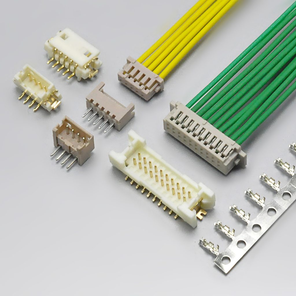
The practical decision rule: flight controllers, drones, compact IoT, and wearables → KR1259; sensor and peripheral wiring needing 125V headroom → KR1250 family; industrial and instrumentation wiring, including dual-row density → KR1256 / KR1258.
Explore the full 1.25mm pitch range · Wire-to-board connector catalogue
Applications and Cable Assembly Options
The JST GH 1.25 / KR1259 combination of compact pitch, positive locking, and low insertion force makes it a fit wherever a board must connect to a small peripheral without a large connector footprint.
| Application | Why the KR1259 fits |
|---|---|
| Drone and flight controllers | The Pixhawk Connector Standard port type; 4-pin and 6-pin assemblies for GPS, telemetry, I²C, CAN, and power |
| Robotics | Compact sensor and bus wiring where a positive lock is mandatory in vibration environments |
| Video cameras and gimbals | Dense internal wiring between boards and modules in a small enclosure |
| Wearable electronics | Weight and height sensitive designs needing a low-profile SMT interconnect |
| Medical devices | Equipment internal wiring, supported by KONNRA’s ISO13485 medical device quality system |
| Cellular phones and consumer devices | High-volume internal board-to-module connections |
| Home appliances | Control board to display and sensor wiring at low voltage |
Cable assembly types
KONNRA builds cable assemblies on the KR1259 system in the standard harness configurations:
| Cable type | Description | Typical use |
|---|---|---|
| Single-headed | Housing on one end, bare wire leads on the other | Pigtail to a wafer, panel wiring |
| Same-side-head | Housing on both ends, same orientation | Board-to-board extension, same-direction routing |
| Reverse-side-head | Housing on both ends, reversed orientation | Board-to-board extension, reversed routing |
Cable assemblies are produced in KONNRA’s wiring harness division, which accounts for 40% of company sales and operates its own injection moulding and assembly workshops. Connector lead time is typically 2–3 weeks; wiring harness lead time is typically 3–4 weeks.
Explore KONNRA wiring harness capabilities
Why Source JST GH 1.25 Connectors from KONNRA
Dongguan Konnra Electronics Co., Ltd. (brand: KONNRA) was founded in 2004 and is a National High-Tech Enterprise specialising in connector and wiring harness research, development, production, and sales. For engineers qualifying a JST GH 1.25 cross-reference, five capability areas are relevant.
Manufacturing depth. KONNRA runs a vertically integrated process covering precision mould design and manufacturing, automation design, precision injection moulding, stamping, assembly, and CCD visual inspection. Automation coverage exceeds 95% across production lines.
Testing and validation. KONNRA operates a CNAS-accredited laboratory equipped with 45+ sets of precision testing instruments, and performs CAE analysis — contact nonlinear analysis, material nonlinear analysis, motion simulation, thermal field analysis, and high-frequency analysis — in Ansys 2022 R1. Verification data is available on request.
Inspection coverage. Full-line intelligent visual CCD inspection covers 95% of production processes, using Mitsubishi and Panasonic PLC control systems with FA25–35mm optical lenses and 5-megapixel cameras. Automotive connector series receive 100% CCD visual inspection.
Quality systems. ISO9001, ISO14001, IATF16949, ISO45001:2018, ISO13485, IPC620, and UL product and operational safety certifications, with automotive-grade series additionally certified to LV214 and US CAR-2.
Capacity and delivery. Production bases span Dongguan Wangniudun (30,000 m², 350+ employees), Dongguan Changan (10,000 m², 150+ employees), and Hunan Daoxian (2,600 m², 100+ employees), supported by regional offices in Beijing, Chongqing, Hunan, Shanghai, and Kunshan. Key materials are prestocked to shorten delivery cycles, and complete connector set samples can be delivered within 45 days. KONNRA reported 2025 sales of RMB 310 million, with connectors accounting for 60% and wiring harnesses 40% of the product mix, and has served global cooperative clients including BYD, Volkswagen, and DJI.
Custom and joint R&D. Where a standard 1.25mm part does not fit — an unusual circuit count, a non-standard wafer height, or a specific material requirement — KONNRA supports customer joint R&D customisation with aligned development timelines and forward-looking cost-reduction planning.
Frequently Asked Questions
What is a JST GH connector?
The JST GH is a 1.25mm pitch, single-row, wire-to-board crimp connector system with a secure locking mechanism and SMT PCB mounting. It consists of a housing, an SMT wafer, and a crimp terminal, rated 1A per contact at 50V AC/DC. The KONNRA KR1259 series is documented as its cross-reference equivalent.
Is the JST GH the Pixhawk standard connector?
Yes. The JST GH 1.25mm connector was adopted as the Pixhawk Connector Standard for the ArduPilot and Dronecode ecosystem, which is why GPS modules, telemetry radios, rangefinders, and power modules for flight controllers ship with GH connectors. The most common configurations are 4-pin (I²C, CAN) and 6-pin (GPS, TELEM, POWER).
What is the KONNRA equivalent of the JST GH 1.25?
The KONNRA KR1259 series — a 1.25mm pitch single-row GH wire-to-board connector with lock, covering 2–16 circuits at 1A and 50V. It consists of an SMT straight wafer, an SMT right-angle wafer, a housing with locking structure, and a terminal.
What is the difference between JST GH and JST SH?
Pitch and application. The GH is 1.25mm; the SH is 1.0mm. Both are rated 1A, both are SMT, and both are used in compact electronics, which is why they are so frequently confused — but they use different housings, different wafers, and different terminals, and they do not mate. The GH is the Pixhawk ecosystem standard; the SH dominates micro FPV builds and ultra-compact boards. Note also that the AWG 28–32 wire range often attributed to the GH is actually the SH’s range — see the wire gauge note above.
Are JST GH and Molex PicoBlade interchangeable?
No. They share a 1.25mm pitch but have different housing geometry, different wafers, and different locking mechanisms, so they will not mate. They also have different voltage ratings — 50V for the GH versus 125V for the PicoBlade. Cross-reference on the specific part number, not on the pitch. The KONNRA equivalents are KR1259 (GH) and the KR1250 family (PicoBlade).
What wire gauge does the JST GH use?
The JST GH terminal (SSHL-002T-P0.2) is documented for 0.05–0.13mm², which is AWG #30–#26, with an insulation diameter of 0.8–1.0mm. The KONNRA KR1259 is documented for the same AWG #30–#26 range with insulation diameter up to 1.0mm. Many third-party listings state AWG 28–32, which is the JST SH range — verify against the manufacturer datasheet before releasing a harness drawing.
What is the current rating of the JST GH / KR1259?
1A per contact. For the GH, JST documents 1.0A AC/DC when using AWG #26 wire. The KONNRA KR1259 is documented at the same 1A with a 50V AC/DC rating. Note that the rating is per contact — where two contacts are paralleled in a power port, the effective capacity is higher than a single contact, but do not extrapolate beyond the published connector rating without engineering review.
Does the JST GH have a locking mechanism?
Yes. The GH has a secure locking function: the housing latches positively to the wafer with a tactile click, and the terminal locking construction retains each crimped contact inside the housing. On the KONNRA side this is the KR1259 Housing.
Does the JST GH come in a through-hole version?
No. JST documents the GH as an SMT-mounted system, and KONNRA documents the KR1259 with SMT straight (180°) and SMT right-angle (90°) wafers. There is no through-hole GH. If your layout assumes a DIP footprint, you need a different series.
What is the operating temperature range?
The JST GH series is commonly documented at −25°C to +85°C. The KONNRA KR1259 is rated −40°C to +105°C, which is relevant for outdoor drone platforms, industrial enclosures, and equipment that sees thermal cycling.
How do I crimp JST GH terminals?
The terminal accepts AWG #30–#26 wire with an insulation diameter up to 1.0mm. Use a ratchet crimper with a die matched to the conductor and insulation crimp dimensions given in the KR1259 product specification, then pull-test every crimp before inserting the terminal into the housing. In 1.25mm terminals, crimp consistency is the dominant failure mode — for volume production, KONNRA can supply pre-crimped cable assemblies so the crimp is controlled in a factory process rather than at the bench.
How long does it take to get samples?
KONNRA can deliver complete connector set samples within 45 days. Connector production lead time is typically 2–3 weeks and wiring harness lead time typically 3–4 weeks.
Request a Quote, Sample, or Cross-Reference Verification
KONNRA supplies the KR1259 series as individual components or as complete pre-crimped cable assemblies, with customisation available for application-specific requirements.
- Request a quote — KR1259 pricing, MOQ, and configuration options
- Request a sample — complete connector set samples within 45 days
- Request cross-reference verification — confirm KR1259-to-JST GH 1.25 equivalence for your specific application before order placement
- Request drawings — series engineering drawing, product specification, and package specification
Contact KONNRA Electronics
- Phone: (86)-769-85449875
- Email: [email protected]
- Address: No.6 Nanchang South Road, Chijiao, Wangniudun, Dongguan, Guangdong, China
- Contact us