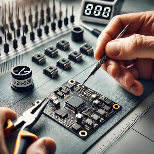
In the early days, most PCB boards used soldering. However, with the upgrading of electronic products, the miniaturization of connectors, and the requirements for high reliability and ecological environmental protection, crimping has become the current mainstream connection method.
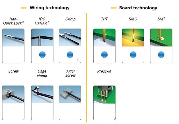
There are many ways to connect connectors, which can basically be divided into two categories: wiring (connecting cables) and connecting boards (connecting PCB). Crimp and Press-in are the most commonly used connection methods among these two categories. Interestingly, the Chinese word for these two connection methods can be expressed as “crimp”.
1Press-in plate technology.
Low cost and high efficiency.
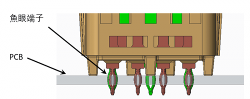
The definition of a press-fit connector is to press the pin (also called a terminal) into a hole smaller than its outer diameter through external force. This press-fit connection method is called a press-fit connection, also known as crimping. Because it has the characteristics of low cost, high efficiency, simple operation and high reliability compared with SMT (surface mount technology, which is a board-level connection technology), it is widely used in communications, computer and other industries.
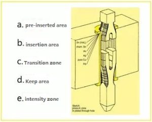
The industry has designed various forms for Press-fit terminals, each with its own advantages and disadvantages. Among them, fisheye terminals are the most widely used press-fit terminal structure. Usually a typical fisheye terminal is divided into 5 areas (as shown in the figure above).
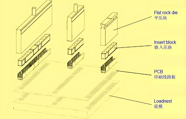
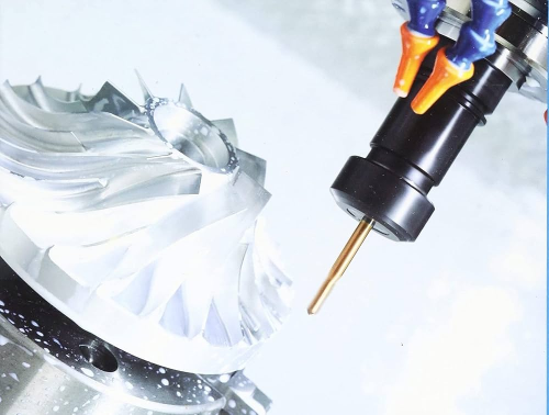
For complex crimping, upper and lower crimping dies are essential.
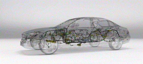
Another special application for press-fit connectors is three-board interconnects (shown above). Compared with current welding technology that can only be used for two-dimensional panels, it has a wider range of uses. Its disadvantage is that it has high requirements on PCB boards. The detection is more complicated, etc.
2 Wiring technology crimping.
The wiring quality is high.
Crimping is a cold pressing technology whose origins date back to around 1940. The principle is to use crimping pliers or crimping tools to complete the crimping of metal wires and pins. This crimp is airtight and corrosion-resistant, and the wire must deform beyond its yield point for reliable data, signal and power transmission. During the crimping process, the remaining elasticity of the crimp pin and wire is used to remove the oxide or vulcanized layer of the wire to ensure a durable electrical connection.
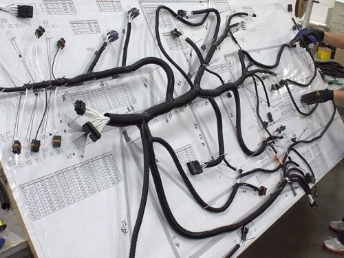
This method is suitable for Category 2, Category 5 and Category 6 wire diameters from 0.08 mm² to 240 mm². There is evidence that solid wire can also be crimped, but the crimp quality needs to be tested to confirm. The figure below is a schematic diagram of different types of cables, stranded wires after crimping, and the internal structure of the stranded wires.
The crimp connection has a compact structure, reliable connection, reliable earthquake resistance, and can be operated on-site using special tools. Compared with ordinary threaded connections, crimping provides the greatest possible connection density, that is, the most connection channels can be provided per unit area. Since its connection principle is cold pressing, the connection is sealed and the connection quality is very high. Crimping is the highest quality known wiring technology.
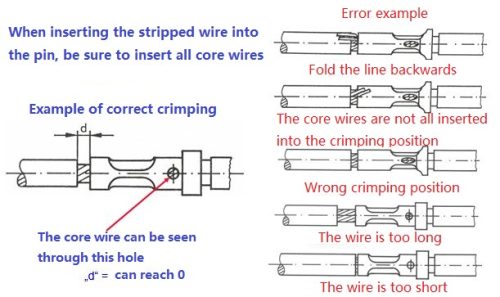
The picture above shows the crimping process of the cable. Through the bell mouth, you can see the crimping condition of the cable and whether the insertion length of the wire core is too long or too short.
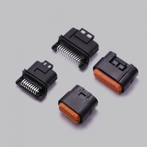
There are two main types of crimp connections: machined crimp pins and stamped crimp pins.
When crimping cables, there are some details to pay attention to during the stripping and sealing process.
When stripping the wire, make sure that the insulation blade is smooth, the wire core is intact, and there is no insulation residue on the wire core. Improper wire stripping will greatly reduce the connection effect. Correct and incorrect wire stripping diagrams are shown above.
Pay attention to the length and depth when inserting. Inserting a cable that is too short can easily result in the terminal not achieving the specified pullout force because the metal-to-metal contact between the cable and terminal is reduced. Inserting the cable too deep will shorten the life of the connector. Taking needle crimping as an example, when the metal wire core can be observed through the first window and the cable sheath is observed through the second window, it means that the position of the wire core is just right.
Crimping is complete. If you want to conduct a comprehensive inspection of the connection effect, you need to conduct pull-out force and cross-sectional inspection, etc., which will not be described here.
Generally speaking, there is no absolute good or bad way of connecting a connector, only whether it is suitable or not. When selecting a plug-in connector, you need to consider the structural requirements of the connector and the on-site use environment to select the appropriate connection method.