The use of nonstandard connectors is more common than most designers think. Many common connectors can be modified to achieve the performance, functionality, and format required for high-performance systems.
Designers typically try to use standard interconnects in their end products. Most cite availability to explain why they insist on using standard, off-the-shelf products. However, sometimes no standard product exists that meets the requirements of a system design, and a custom or modified interconnect is ultimately chosen.
The use of nonstandard connectors is more common than most designers think. For example, about 25% of Samtec’s sales are nonstandard products, ranging from slight modifications of existing products to completely new connector systems. These products include high-speed board-to-board (mezzanine) systems, high-speed cable assemblies, backplane board and cable systems, two-piece pin and socket systems, active optical cable assemblies (called “mid-board optical transceivers” in Samtec’s new Optics Guide), and RF connector and cable assemblies.
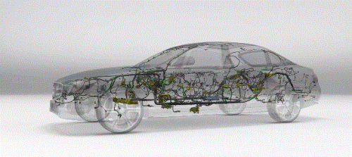
Designers of high-speed systems (112 Gb/s PAM4 per lane data rates, 224 coming soon) such as data centers, supercomputers, automated test equipment, and medical imaging often use high-speed cable assemblies to transmit large amounts of data at high data rates.
While there are a variety of standard high-speed cable assemblies, many customers specify modifications to these standard products. Common modifications include custom PCB design for application-specific pin mapping, placing a protective sleeve around the low-skew twinax cable, or adding labels to the connector and cable to identify the part number or provide instructions, to name just a few of the hundreds of potential modifications that can be made.

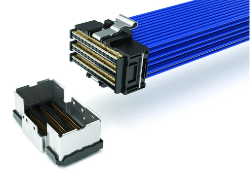
Many designers modify high-speed cable assemblies to meet their system requirements.
Above: Samtec’s AcceleRate® HP High-Density Cable System
Another popular modification is to mix and match the end 1 and end 2 connectors of a component. For example, a Flyover® QSFP-DD front panel connector can terminate to any number of high-density end 2 connectors placed near the chip. Designers require a variety of connector types for front-, mid-, and back-panel interconnect systems.
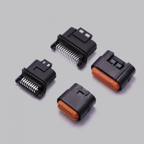
Cutting-edge, high-speed systems require next-generation, high-performance connectors. However, many manufacturers have designs for more “straightforward” applications such as industrial automation, robotics, embedded products, and vision and safety systems. These boxes often use more basic, traditional interconnects such as square-post terminals (“headers”) and socket strips. The relative simplicity of these products’ designs — stripline plastic insulators and non-micro centerlines (e.g., 2.54 or 2.00 mm vs. 1.00 or 0.80 mm pitch) — makes modifications simple and relatively quick, and therefore inexpensive.

Popular modifications include multi-pin polarization – removing pins – to allow for keying, airflow, signal mapping and additional space for power delivery or creepage and clearance to meet safety and regulatory standards
Above: Modified Samtec terminal strip
Popular modifications include multi-pin polarization – removing pins – to allow keying, airflow, signal mapping and additional space for power delivery or creepage and clearance to meet safety and regulatory standards. Most designers using board-level connectors try to achieve UL and CE 61800-5-1 specifications, which specify creepage and clearance distances for a given material grade, working voltage and pollution degree.
Another popular modification is the addition of alignment and polarization features such as shrouds, lead-ins, and blind-mating support, as well as combining power and signal pins into a single connector. Combining power and signal pins into a single connector system saves PCB space and improves tolerances of mating connector sets.
Most board-to-board connectors have carefully designed signal-to-ground configurations to achieve SI (signal integrity) performance, which requires low mode conversion to reduce radiated noise or susceptibility to noise. If additional shielding performance is required, the connector can be enclosed in an external metal shield that surrounds the entire mating connector system to minimize the effects of EMI and EMC.
Plating is another common modification; this includes heavy gold, silver, and palladium nickel, among others. Most designers are targeting higher cycle counts, protection from harsh environments, shock and vibration, and higher operating temperatures.
All of the examples cited above are modifications to existing connectors. Some systems require entirely new connectors that may include custom pins and stampings, plastic insulators and housings, custom RF, metals, special packaging, custom housings and packaging, etc.