In the ever-evolving world of electronics, the role of connectors cannot be understated. Among these, the FPC (Flexible Printed Circuit) connector stands out due to its unique capabilities and applications. FPC connectors are vital components that enable the efficient and reliable operation of various electronic devices. Companies like KONNRA, a leading name in the electronic connector industry, have been at the forefront of developing advanced FPC connectors that meet the demands of modern technology. This blog will discuss the significance of FPC connectors, delving into their basic definitions, primary uses in electronic devices, key specifications, mechanical and environmental standards, and tips on how to read and understand their datasheets.
Ⅰ. Introduction to FPC Connectors
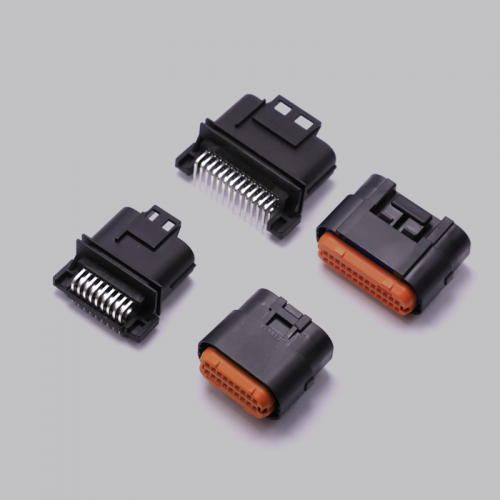
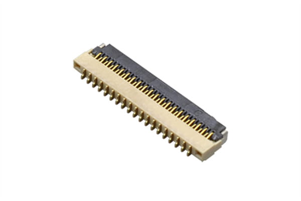
FPC connectors, or Flexible Printed Circuit connectors, are a type of connector used to connect flexible printed circuits to rigid printed circuit boards (PCBs) or other electronic components. They are known for their flexibility, light weight, and compact size, making them ideal for various applications where space and weight are critical factors. Unlike traditional rigid PCBs, FPCs can bend, fold, and conform to different shapes, providing greater design flexibility and enabling more compact and versatile electronic devices.
Ⅱ. Primary Uses of FPC Connectors in Electronic Devices
1.Consumer Electronics
FPC connectors are widely used in consumer electronics due to their versatility and reliability. In smartphones, they connect various internal components, such as the display, camera, and touch screen, to the main PCB. Their flexibility allows for sleek and slim designs, contributing to the overall aesthetic and functionality of the device. Tablets and laptops also benefit from FPC connectors, which facilitate the connection of keyboards, touchpads, and displays, ensuring a seamless user experience.
2.Medical Devices
In the medical field, FPC connectors play a crucial role in portable and wearable medical devices. Their small size and reliability make them suitable for devices such as hearing aids, glucose monitors, and portable diagnostic equipment. The ability to withstand repeated bending and flexing ensures that these devices remain functional and reliable over extended periods.
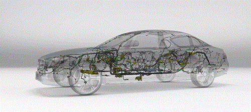
3.Automotive Industry
The automotive industry has seen significant advancements in electronic systems, and FPC connectors have become integral components in this sector. They are used in various applications, including infotainment systems, advanced driver assistance systems (ADAS), and interior lighting. The flexibility of FPC connectors allows for easy integration into the complex and compact spaces within vehicles, enhancing both functionality and design.
Ⅲ. Basic Specifications of FPC Connectors
1.Pin Count
The pin count of an FPC connector refers to the number of electrical contacts or terminals it has. This specification is crucial as it determines the connector’s capacity to handle multiple signals and power lines. Each pin can carry a separate electrical signal or power, so a higher pin count allows the connector to interface with more complex circuits that require numerous connections. For example, in a smartphone, a high pin count connector might be necessary to connect various components such as the display, camera, and sensors to the mainboard. Conversely, simpler applications like connecting a single sensor to a control board might only require a connector with a few pins.
2.Pitch
Pitch is the distance between the centers of adjacent pins on the connector, typically measured in millimeters (mm). This dimension is critical because it affects the overall size of the connector and its compatibility with the mating components. Common pitch sizes for FPC connectors range from 0.5mm to 1.25mm. Smaller pitch sizes, such as 0.3mm or 0.5mm, are used in applications where space is at a premium, such as in ultra-thin laptops or compact wearable devices. Larger pitch sizes are easier to manufacture and more robust, making them suitable for less space-constrained applications where mechanical strength is a priority.
3.Contact Type
FPC connectors come in various contact types, which determine how the connector interfaces with the flexible printed circuit. The main types are:
Top Contact: These connectors make contact with the conductive traces on the top side of the FPC. They are often used in applications where the FPC is laid out in a manner that requires top-side connections.
Bottom Contact: These connectors interface with the conductive traces on the bottom side of the FPC. Bottom contact connectors are typically used when the design necessitates connections on the lower side of the FPC.
Dual Contact: These connectors can connect to both the top and bottom sides of the FPC, providing greater versatility. Dual contact connectors are beneficial in designs where signals or power need to be transmitted from both sides of the FPC.
Choosing the correct contact type is essential for ensuring a reliable electrical connection and optimizing the layout and assembly of the electronic device.
4.Voltage and Current Ratings
Understanding the voltage and current ratings of an FPC connector is essential to ensure safe and reliable operation. These ratings indicate the maximum voltage and current the connector can handle without degrading its performance.
Voltage Rating: This is the maximum voltage the connector can handle. It is important to ensure that the voltage rating of the connector matches or exceeds the voltage requirements of the application. Using a connector with an inadequate voltage rating can lead to electrical breakdowns or arcing, which can damage the connector and the surrounding circuitry.
Current Rating: This is the maximum current the connector can carry through each pin without overheating. Exceeding the current rating can cause the connector to overheat, leading to potential melting or fire hazards. It is crucial to consider the current requirements of your application and ensure that the connector can handle the total current load safely.
Manufacturers provide these ratings based on standard testing procedures, and it is essential to adhere to these specifications to maintain the integrity and reliability of the electronic device.
Ⅳ. Mechanical and Environmental Specifications of FPC Connectors
1.Mechanical Strength and Durability
Mechanical specifications, such as mating cycles, insertion force, and retention force, are critical factors that determine the durability and reliability of FPC connectors. Mating cycles refer to the number of times the connector can be connected and disconnected without significant wear. Insertion force is the amount of force required to insert the FPC into the connector, while retention force is the force needed to maintain a secure connection. High-quality connectors, like those from KONNRA, are designed to withstand numerous mating cycles and provide consistent performance.
2.Environmental Resistance
FPC connectors must perform reliably under various environmental conditions, including temperature extremes, humidity, and vibration. Temperature ratings specify the range within which the connector can operate without performance degradation. Humidity resistance ensures that the connector maintains its integrity in moist environments, while vibration resistance is crucial for applications subjected to mechanical stress, such as automotive and industrial electronics.
3.Materials and Plating
The materials used in FPC connectors and their plating significantly impact their performance and longevity. Common materials include polyimide for the flexible substrate and copper for the conductive traces. Plating options, such as gold or nickel, are used to enhance the connector’s durability and electrical conductivity. Gold plating, for example, provides excellent corrosion resistance and ensures low contact resistance, making it ideal for high-reliability applications.
Ⅴ. How to Read and Understand FPC Connector Datasheets
1.Datasheet Structure
A typical FPC connector datasheet is structured to provide detailed information on the connector’s specifications, including electrical, mechanical, and environmental characteristics. The datasheet usually starts with a general description of the product, followed by tables and graphs outlining specific parameters.
2.Key Parameters Explained
To effectively use an FPC connector, it is essential to understand key parameters such as contact resistance, insulation resistance, and dielectric withstanding voltage. Contact resistance measures the resistance at the interface between the connector contacts and the FPC, with lower values indicating better performance. Insulation resistance is the resistance between adjacent contacts, ensuring that there is no unwanted electrical leakage. Dielectric withstanding voltage specifies the maximum voltage the connector can withstand without breakdown.
Ⅵ. Conclusion
FPC connectors are critical components in modern electronic devices, offering flexibility, reliability, and compactness. Companies like KONNRA are at the forefront of developing high-quality FPC connectors that meet the demanding requirements of various industries. Understanding the specifications of FPC connectors and how to interpret datasheets is essential for making informed decisions and ensuring optimal performance in electronic applications. By comprehending these details, engineers and designers can optimize their applications, ensuring reliability and efficiency in their products.