High-performance automotive technology requires new electrical design strategies and advanced connectors to address these challenges.
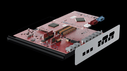
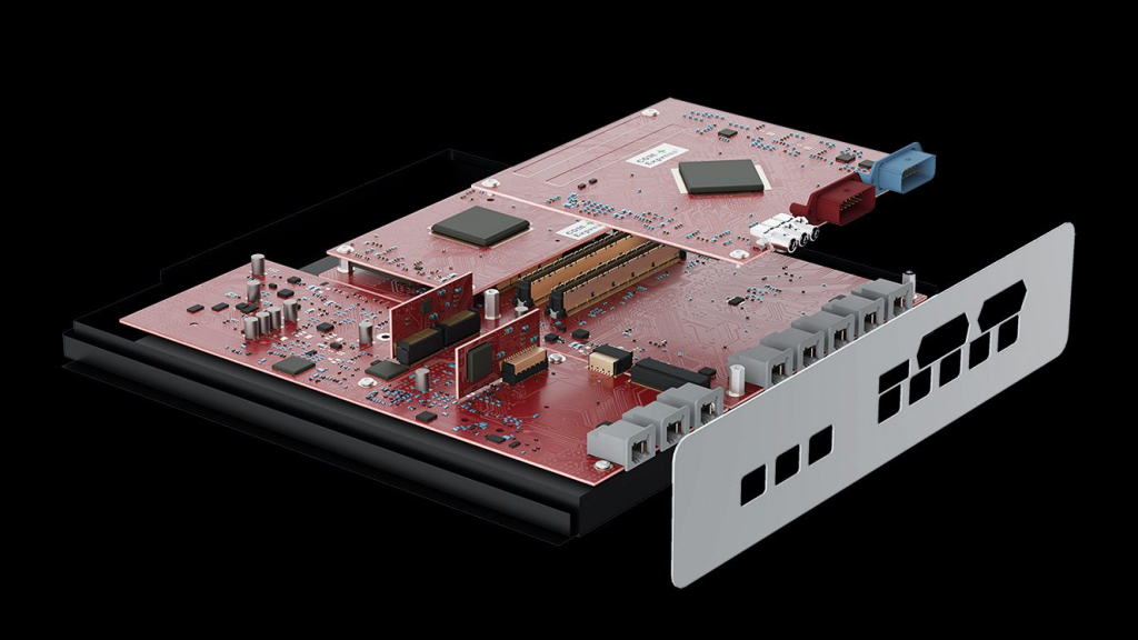
With the popularization of high-performance vehicle technology and the development of electric vehicles, the traditional distributed electrical system architecture has become insufficient. The complexity and speed demands of technologies such as advanced infotainment, safety systems, autonomous driving and vehicle-to-infrastructure communication networks are driving new design strategies and connectors.
Ⅰ. Vehicle electrical systems: distributed, domain and zone architectures
Vehicle electrical system architecture:
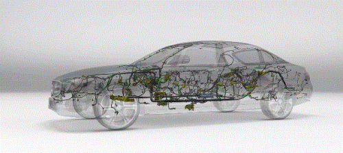
- Distributed architecture : Traditional architecture consists of up to 100 control units, each responsible for specific functions, such as engine control, seat adjustment, etc. As functionality increases, the wiring and interconnections in each vehicle also increase significantly.
- Domain architecture : The control unit is divided into different functional areas, each of which is controlled by an independent high-performance computer (HPC). The domain architecture reduces the number of control units and wiring complexity, thereby reducing vehicle weight and cost.
- Regional architecture : Functions are organized by region, such as powertrain and infotainment functions are concentrated in one regional controller. The central HPC hosts the regional controllers, reducing the number of control units and the amount of wiring.

Figure 1: Schematic diagram of the electrical system architecture of a high-performance vehicle.
Image courtesy of ept GmbH
Ⅱ. High reliability and performance requirements
HPC and its interconnect design must meet high performance standards, especially in autonomous driving systems, which have strict requirements for high-speed data transmission and low latency. Signal transmission must be highly reliable, especially in harsh environmental conditions. To prevent electromagnetic interference, high-speed signals need effective protection, and shielding plates and appropriate connector design are key.
Coupled inductors are used to determine electromagnetic compatibility and help select the right connector, avoiding the high cost and time consumption of repeated trials. Connectors must be rugged and able to maintain stable signal transmission under extreme conditions such as vibration and shock. Contact design and termination technology are critical in ensuring signal reliability.
Ⅲ. Strategic contact design for harsh environment reliability
Contact Design and Termination Technology:
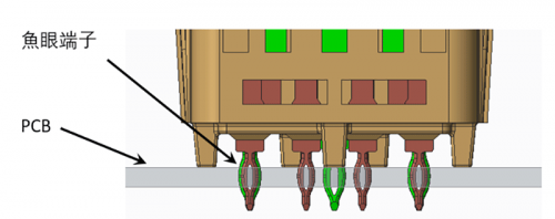
Conventional two-piece connectors may fall off under strong impact. We recommend using surface mount technology (SMT) to ensure the stability of the connection. SMT technology solders the connector to the PCB through solder paste and melts and hardens the solder through a reflow oven to ensure high-quality connections. Solder connections that meet IPC A-610 standards ensure reliable signal transmission. The best solder connections can be identified by the uniform formation of the meniscus. The entire circumference of the contact must be wrapped by the solder meniscus to achieve the best retention force on the PCB.

Figure 2: Uniform meniscus formed around the weld leg
To achieve a good connection, the contact pins must be coplanar. The coplanarity is checked in a fully automated process.
KONNRA connectors always put quality first . KONNRA has not only passed strict quality testing and certification, but also obtained the recognition of international authoritative certification bodies such as UL, IATF16949, and ISO9001. These certifications are not only an affirmation of the quality of KR1500 Series Pico Spox Wire to Board Pin Connector, but also a recognition of KONNRA connectors’ level of connector product manufacturing . Choosing KONNRA means choosing a reliable and efficient partner .
