I. What is a pin header?
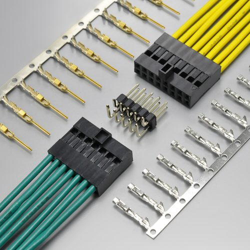
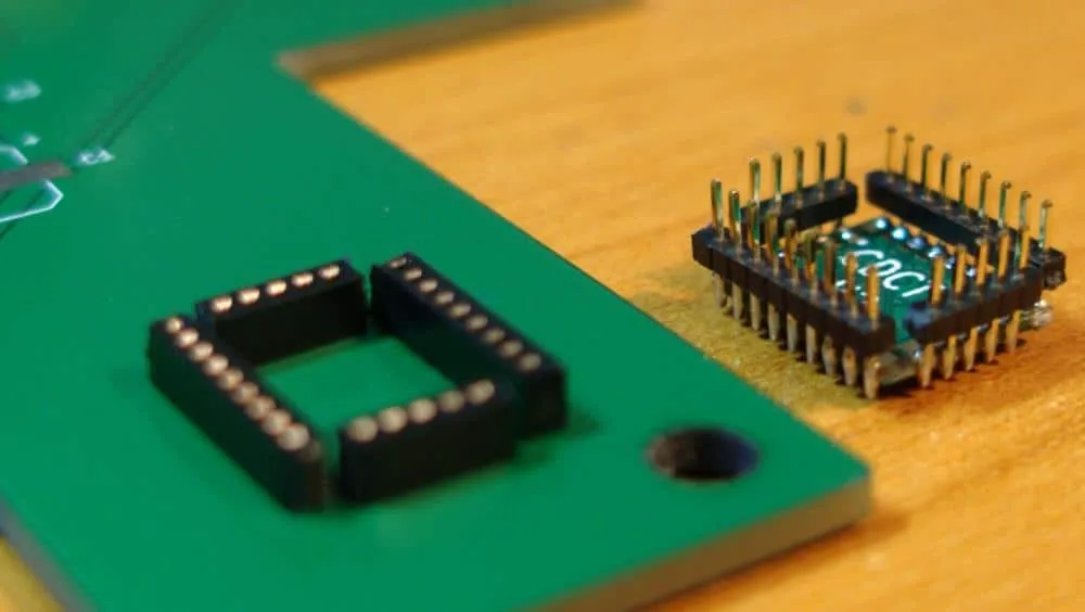
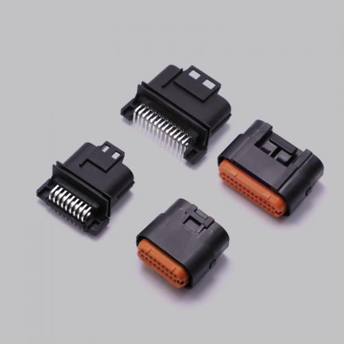
Pin header is a product in the connector industry, with the reputation of universal connector. Along with the competition in the connector market, nowadays pin header connectors are widely used in PCB circuit boards in electronics, electrical appliances and instruments. The pin header is usually used in conjunction with the female headers, constituting the effect of board-to-board connection, or used in conjunction with the line terminals, constituting the wire-to-board connection, but also can be used independently for board-to-board connection and so on.
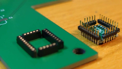
The original row of pins was manufactured by Berg Electronics Corporation (now part of Amphenol), so pin headers are sometimes called Berg connectors. Today, many companies manufacture them, and pin headers are used in a wide range of industries, including video, lighting, portable devices, telephone service, electronics, industrial automation, healthcare, and energy.
II. Design application of pin header
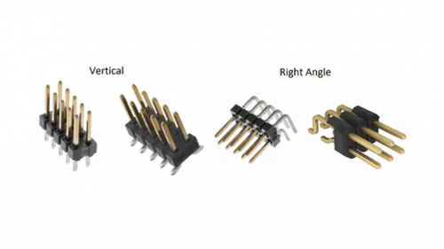
The orientation of PCB pin header depends on the particular pin and its intended use. Typically, the pin header can be arranged in a vertical, right-angle, or L-shaped configuration. Designers must carefully consider the orientation of the pin header when designing the PCB pinout to ensure that they are correctly matched to the corresponding connectors.
Depending on their design and application, manufacturers orient pin header connectors in different ways. The most common orientation is:
Vertical: The pin headers are arranged in a straight line and perpendicular to the PCB. Orientation can be determined when the pin header is located at the edge of the PCB or connected to a straight connector
Right Angle: The pin headers are arranged in a right angle configuration to allow the connector to be mounted parallel to the PCB surface. This orientation is a common choice when space is limited and mating connectors are also oriented at right angles.
III. Common data for pin headers
Pin headers are sold in long strips, usually with 36, 40 or 50 pins, and can be easily cut to the desired number of pins, providing a variety of pin lengths to minimize the amount of labor involved in the PCB assembly process.
Header types are characterized by pitch (the distance between the center of one pin to the the center of the next pin).
Common pin spacing are:
- 5.08 mm
- 1.27 mm
- 3.96 mm
- 2.54 mm with 0.64 mm square pins or precision machined 0.50 mm round pins
- 2.00 mm with 0.50 mm square pins
Pin headers are also defined by multiplying the number of pins by the number of rows. For example, the pin header with two rows of eight pins is identified as an 8 x 2 header.
IV. Anti-dulling design
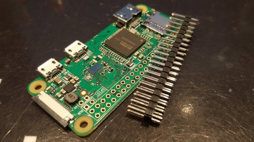
1. A plastic deflector box (hood) with a square notch surrounds the shrouded row of pins, also known as the boxed row of pins, to ensure that connectors are not placed incorrectly. Shrouded pins are used with insulation displacement connectors (IDCs) for ribbon cables.
2. Filling or plugging a hole in the socket (called polarization) also prevents mismatching. A pin of the wrong header or a header rotating in the wrong direction will hit an obstruction. thus preventing misconnections.
V. Pin Header Recommendations
KONNRA KR2542 pin header accommodate different forms, pitches, heights, and mounting orientations to provide a flexible, reliable, and rugged solution for a variety of applications from industrial to consumer electronics.
