As an integral part of the complete device, the PCB board basically cannot constitute an electronic product, and there is inevitably a problem of external connection. For example, electrical connections are required between PCB boards, between PCB boards and off-board components, and between PCB boards and equipment panels. It is one of the important contents of printed board design to choose the connection with the best combination of reliability, process and economy. There are many kinds of external connection methods, which should be flexibly selected according to different characteristics.
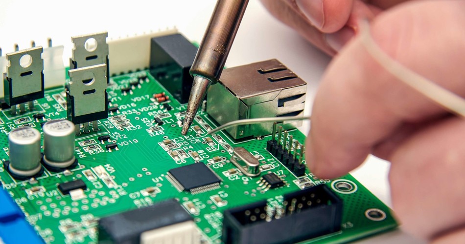
Circuit board interconnection mode 1: welding mode
The advantages of the connection mode are simple, low cost, high reliability, and can avoid the fault caused by poor contact; The disadvantage is that the interchange and maintenance are not convenient enough. This method is generally suitable for the case where the component has fewer external leads.
This method does not require any connectors, as long as the external connection point on the PCB printed board is welded directly with the components or other components outside the board. For example, the speaker in the radio, the battery box, etc.
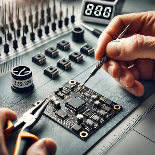
- PCB wire welding
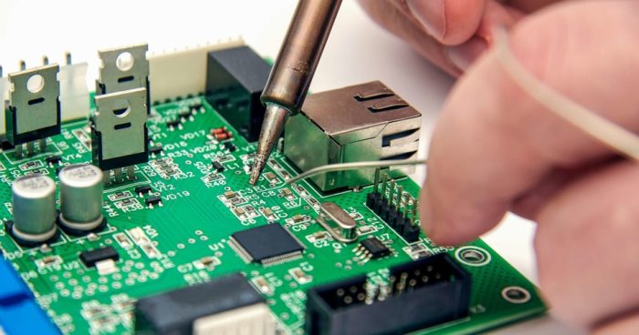
Circuit board interconnection welding should pay attention to:
(1) The welding pad of the welding wire should be as far as possible on the edge of the PCB printed board, and arranged according to a unified size to facilitate welding and maintenance.
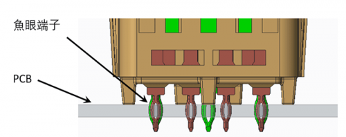
(2) In order to improve the mechanical strength of the wire connection and avoid pulling the solder pad or printed wire off due to the pull of the wire, drill holes near the solder joints on the PCB printed board, let the wire pass through the hole from the welded surface of the printed board, and then insert the solder pad hole from the component surface for welding.
(3) Arrange or bundle the wire neatly, and fix it with the board through the wire card or other fasteners to avoid breaking the wire due to movement.
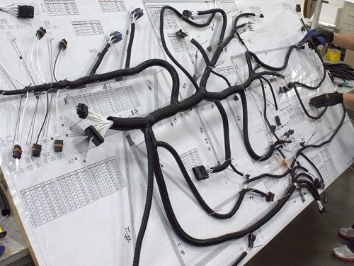
- PCB wiring welding
The two PCB printed boards are connected by a line, which is reliable and not easy to make connection errors, and the relative position of the two PCB printed boards is not limited. Printed boards are welded directly between each other. This method is often used for connections where the Angle between two printed boards is 90 degrees. After connecting to form an integral PCB printed board component.
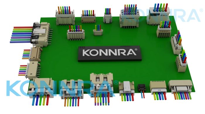
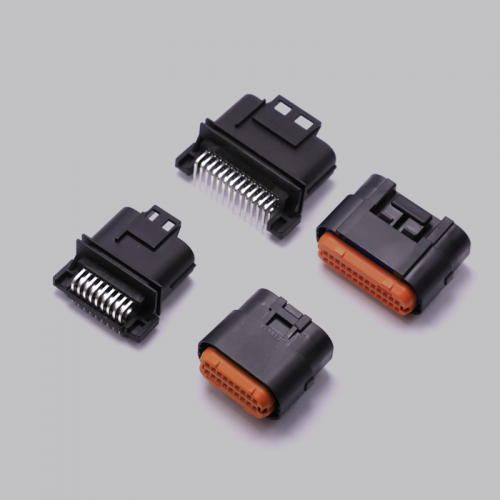
In more complex instruments and equipment, the connector connection is often used. This “building block” structure not only ensures the quality of mass production of products, reduces the cost of the system, and provides convenience for debugging and maintenance. When the equipment fails, the maintenance personnel do not have to check the component level (that is, check the cause of the failure, and trace the source to the specific component. This work takes quite a lot of time), as long as it is determined which board is not normal, it can be replaced immediately, troubleshoot in the shortest time, shorten the downtime, and improve the utilization of equipment. The replaced circuit board can be repaired in sufficient time and used as spare parts after repair.
- Printed board socket
This connection method is often used in more complex instruments and equipment. This method is to make a printed plug from the edge of the PCB printed board, and the plug part is designed according to the size of the socket, the number of connections, the distance of the contact, the position of the positioning hole, etc., so that it matches the special PCB printed board socket.
When making plates, the plug part needs to be gold-plated to improve wear resistance and reduce contact resistance. This method has the advantages of simple assembly, good interchangeability and good maintenance performance, and is suitable for standardized mass production. Its disadvantage is that the cost of printed board increases, and the manufacturing precision and process requirements of printed board are higher; The reliability is slightly poor, often due to oxidation of the plug part or aging of the socket reed and poor contact. In order to improve the reliability of external connections, the same lead wire is often led out in parallel through the contacts on the same side or both sides of the circuit board.
PCB printed board socket connection method is often used in products with multi-board structure, the socket and printed board or bottom plate have reed type and pin type.
- Standard pin connection
This method can be used for the external connection of printed boards, especially in small instruments often used pin connection. The two printed boards are connected through standard pins, and the two printed boards are generally parallel or vertical, which is easy to achieve mass production.