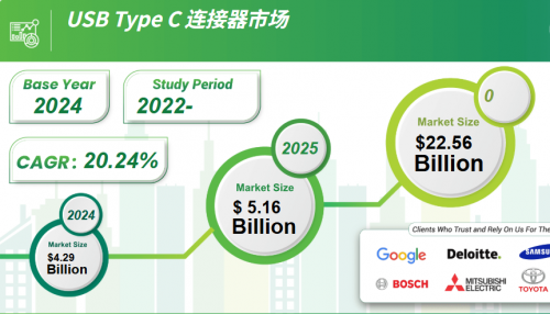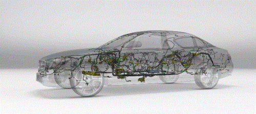
With the rapid development of the automobile industry towards new energy and intelligence, various functional parts and components on automobiles are constantly developing towards intelligence, refinement and reliability. Similarly, automotive connectors that transmit signals and currents are gradually developing towards high reliability, high density, miniaturization, high speed, standardization, integration and modularity. With the increase in high density and the number of pins, the design of plug-in force needs to be considered in the development process of connectors. The plug-in force not only affects the ease of connector assembly and disassembly, but is also related to the electrical performance of the connector. In actual production, there are many factors that affect the plug-in force. This article discusses the relationship between the plug-in force of the male terminal of the automotive connector and the type and thickness of the plating.
Common plating types for connector terminals
The terminals made of copper alloy in the connector play the role of transmitting signals or currents. In order to protect the terminal substrate from corrosion and optimize the performance of the terminal surface, the terminals are usually surface treated, i.e. electroplated. Depending on the application and environmental requirements, there are usually different types of plating, such as matte tin, reflow bright tin, tin-lead, silver, gold, and palladium nickel flash gold.
Comparative analysis of the effects of different plating layers and thicknesses on terminal insertion and extraction forces
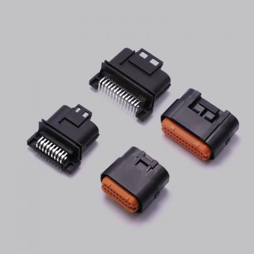
Male terminal: The same 0.64mm unplated terminal commonly used in automotive connectors, with corresponding plating treatment as needed; Female terminal: For comparative analysis, all female terminals use the same specification of Aptiv OCS 0.64mm tinned female terminal.

Comparison of male terminal sample status of different electroplating types : The nickel bottom layer thickness of all terminals is 1.27~2.3μm, and the top layer thickness is defined as 2~4μm for reflow bright tin, matte tin, tin-lead and silver according to the conventional specifications of the automotive connector industry, while the thickness of gold is 0.5~0.8μm, and palladium nickel flash gold is palladium nickel 0.5~0.8μm plus flash gold 0.076~0.150μm. Due to the high hardness of gold, the terminal surface becomes hard after electroplating gold and palladium nickel flash gold, and other electroplating types become soft, with tin-lead being the softest. The surface roughness comparison results are shown in Figure 4. As shown in Figure 4, the surface roughness of different electroplating types is in the following order from small to large: reflow bright tin, tin-lead, before electroplating, palladium nickel flash gold, gold, matte tin, silver (average value).

Figure 4 Surface roughness comparison
The insertion force comparison results are shown in Figure 5. As shown in Figure 5, the insertion force of terminals of different electroplating types is in the following order from large to small : tin-lead, silver, palladium-nickel flash gold, matte tin, before electroplating, reflow bright tin, gold (average value). This is the comprehensive result of surface hardness and surface roughness. It can be seen that gold has better insertion force performance, while tin-lead is relatively poor.

Figure 5 Insertion force comparison
The pull-out force comparison results are shown in Figure 6. As shown in Figure 6, the order of pull-out force of terminals with different electroplating types from large to small is: tin- lead, matte tin, reflow bright tin, silver, before electroplating, gold, palladium nickel flash gold (average value). It can be seen that gold has better pull-out force performance, while tin-lead is relatively poor.

Figure 6 Pull-out force comparison
The comparison results of different electroplating bottom nickel thicknesses are shown in Figures 7 to 11.

Figure 7 Bottom nickel thickness

Figure 8 Hardness comparison

Figure 9 Surface roughness comparison

Figure 10 Insertion force comparison

Figure 11. Comparison of extraction force
Male terminal sample status: The terminal nickel bottom layer thickness is divided into 3 different specifications of 1.27~2.3μm, 2.3~3.3μm and 3.3~4.3μm for comparison, and the top layer thickness is all matte tin 2~4μm. As can be seen from the figure, in the case of matte tin plating on the outer layer of the nickel bottom, the surface hardness of the plating layer after plating is softer than before plating, and the thicker the bottom nickel, the harder the hardness; the insertion force after plating is greater than before plating, and due to the relationship between size and roughness, the thicker the bottom nickel, the greater the insertion force; the pull-out force after plating is greater than before plating, but the pull-out force after plating is not necessarily related to the thickness of the bottom nickel.
Comparison of different electroplating top matte tin thickness Male terminal sample status: The terminal nickel bottom layer thickness is 1.27~2.3μm, and the top matte tin thickness is divided into 1~2μm, 2~4μm and 4~6μm 3 different specifications for comparison. Comparison of different electroplating top matte tin thickness

Figure 12 Top matte tin thickness

Figure 13 Hardness comparison

Figure 14 Surface roughness comparison

Figure 15 Insertion force comparison

Figure 16 Pull-out force comparison
It can be seen from the figure that when the outer layer of the nickel base is plated with matte tin, the surface hardness of the plated layer after plating is softer than that before plating, and the thicker the top layer of matte tin, the harder the hardness; the surface after plating is rougher than before plating, but the thicker the top layer of matte tin, the smoother the surface; the insertion force after plating is greater than that before plating, and the thicker the top layer of matte tin, the greater the insertion force; the pull-out force after plating is greater than that before plating, but the thicker the top layer of matte tin, the smaller the pull-out force.
Conclusion
The plugging and unplugging force of a connector is one of the key indicators of its mechanical performance. Although it is mainly determined by the selected mating female terminal and the structure of the female connector, for the manufacturer of the board-end male connector, when the female connector is selected, the plugging and unplugging force performance of the connector system can only be improved by improving the male connector itself, such as the mating dimensions of the male housing interface, the material, thickness, position and electroplating specifications of the terminal .