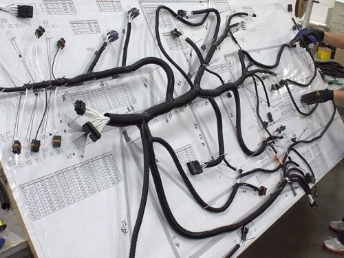
- Board-to-board connectortesting and testing methods
Testing and inspection of board-to-board connectors:
1.1 Observe that the load voltage on the board-to-board connector should not exceed 50% of its rated voltage.
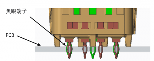
1.2 Installation dimensions of board-to-board connectors For connectors, the length of the soldering pins on the PCB requires that the exposed part of the PCB board be greater than 0.5MM.
1.3 For board-to-board connectors with relatively dense precision, try to choose models with less positioning if the PCB space allows, to facilitate manual soldering operations.
1.4 Check whether there is fool-proof design
1.5 Check whether the materials used in board-to-board connectors contain lead.
1.6 Small size board-to-board connectors have low contact pressure. When using lower currents and voltages, it is recommended to use gold or silver plated connectors to avoid membrane resistance affecting the signal.
1.7 Pay attention to the height of the board-to-board connector after plugging to see if it meets the soldering height of the components around the PCB. The matching height must be greater than the soldering height of the components around the PCB, and there must be a certain margin to ensure that no interference will occur. Pay special attention to component height errors that may occur after PCB welding.
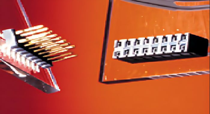
- Board-to-board connection problems and common troubleshooting
Properly connecting board-to-board connector products can increase the service life of the product and ensure the good operation of mechanical equipment. If a board-to-board product fails and is not dealt with in time, it will cause immeasurable economic losses.
2.1 About the connection of board-to-board connectors
Board-to-board plugs and sockets are used to electrically connect two separate circuit boards. It includes a first connector conductively connected to the circuit board and an adapter connector for connecting the first connector in series, wherein the first connector has a first terminal conductively connected to the circuit board and a body for receiving the first terminal. The adapter connector has a second terminal and a body for accommodating the second terminal. The two extended tail ends of the second terminal can be respectively plugged and matched with the first terminal to achieve connection with the circuit boards respectively provided on the two circuit boards. The electrical connection of the first connector is characterized in that the end of one of the first terminal and the second terminal is provided with a reversely bent elastic part, and the body and the second terminal can be arranged according to the spacing standard of the circuit board. Choose a moderate extension length.
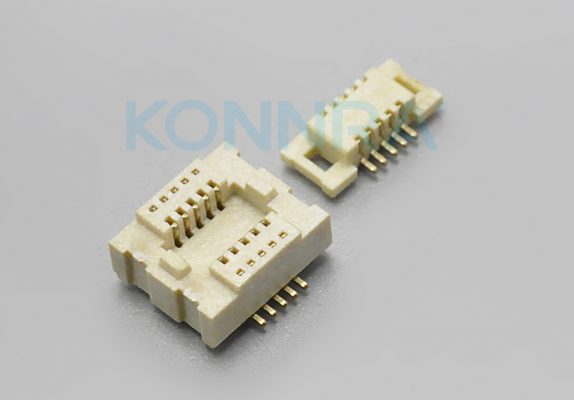
2.2 About troubleshooting board-to-board connectors
Once a product fails, it can be determined that the cause is disconnection during use, product looseness, etc. The frequency of disconnection in the middle is not many, and most of them are disconnection at the connector. Therefore, the focus of the inspection should be on the sensor and the wires connected at the same location to see if they are loose or have poor contact. Generally, circuit breakage caused by poor contact is mostly due to rust at the end of the product, and external dirt entering the terminal or connecting socket, resulting in a drop in contact pressure. To deal with this type of fault, you need to unplug the connector and reinsert it to change its connection status and restore normal contact.
