
After the last KONNRA Connector 7s Management article was posted, many of you wondered why pullbacks? And what is Pullback?
Pull back is a step in the electronic connector assembly process, need to pull back the electronic connector is a very important part – terminals, pull back is to confirm that the barbs of the connector terminals are installed accurately and correctly, to avoid human error.
Ⅰ. Barbs
Connector terminals are mainly used as a bridge for information or current connection in connector products, in order to ensure that the terminals can be firmly fixed in the plastic, terminal barbs structure and plastic interference design is particularly important. Firm contact is mainly achieved by terminal barbs and Housing interference, so barbs are one of the key elements of connector design.
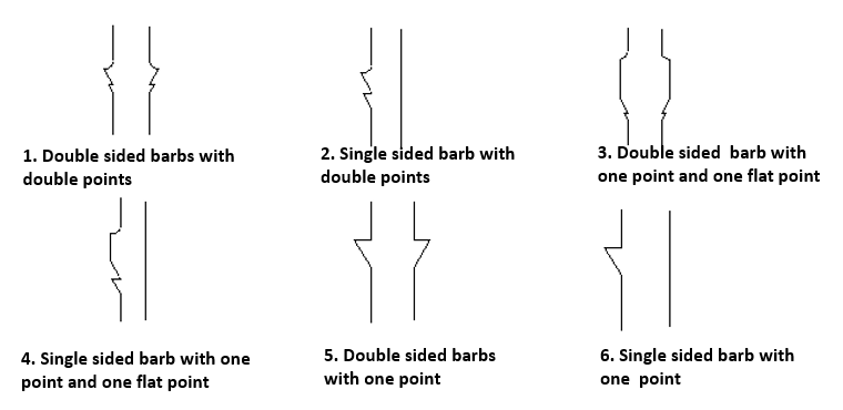
Electronic connector engineers according to the different needs of customers will choose different barbed design, the following six is the current market mainstream connector terminal barbed design.

Figure 1: 6 common terminal barb patterns
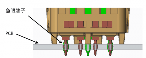
The figure below shows the situation under the microscope when the barbs interfere with the plastic material. When the pin is inserted, the material is scraped and piled up on the sides and front. When the pin is inserted into place, the squeezed material will bounce back, but the plastic cannot return to its original state after bouncing back, but only partially bounces back, the amount of bouncing back is about 0.04mm (the amount of interference is 0.07mm). During the extraction process, the barbs will scrape off the rebounded material; the material squeezed at the end of the insertion of the barbs will rebound when the barbs are removed. When the Pin is completely withdrawn, the plastic groove with the Pin will become bigger because the barbs will scrape off the material, and then insert the terminal again, the holding force will be greatly reduced. Therefore, before the installation process, pay attention to the orientation of the installation, there is a high probability that the plastic groove can not be used again after the installation error.

Figure 2: Terminal barbs and plastic material interference situation
The retention force as shown in the figure below consists mainly of F1 ,F2 due to the scraping of the material, so the parameters that geometrically affect the retention force are A, B, D, E, F and G. The retention force is the result of the scraping of the material.

Figure 3: Components and influencing parameters of holding force
The holding force is also related to the interference volume: the larger the interference volume, the larger the holding force. For the same interference height case. The interference volume depends on the interference length C.
The size of the parameter C has an effect on the holding force, but a larger force area also causes an increase in the stress distribution area inside the housing, leading to deformation and thus cracks in the plastic. Therefore, the setting value should not be too large. Depending on the material, the setting will be different, LCP material should be larger than HTN.

Figure 4: Effect of parameter C on stress distribution inside Housing
II. Problems of barbed technology in connectors with thin plastic bodies
The following discussion focuses on the problems of barbed technology in connectors with thin plastic bodies. Two case studies are presented to explore the contact gap between the barbs and the retaining force/finished product, and the interference situation is observed through microscope to optimise the main parameters of the barbed design.
A. Barbed structure design problem when assembling wire end and board end, take FPC connector as an example:
It is found that the connector terminals are cocked higher than the housing step, resulting in that when advancing the stuffer after inserting the FPC into the connector, the stuffer will be on top of the terminal head, making it difficult for the stuffer to advance. The reason is that when the stuffer is pushed in, it interferes with the rotating metal terminal (Contact). The gap between the front of the metal terminal barbs and the Housing pin hole was small, and during the press-in process, plastic shavings accumulated and the lower wall of the metal terminal rotated. To improve this problem, the engineers increased the clearance between the front of the metal terminal and the Housing pin hole to accommodate the plastic chips.

Figure 5: Barbed structure design problem when assembling wire end to board end
B. Barbed structure design problem in connector assembly process: Gap1 is 0.12mm larger than Gap2 on average.
Originally the contact was slightly rotated (1.02 degrees down, Gap i.e. about 0.12mm difference) due to the metal terminal scraping more heavily at the far glue port and less near the port.
In this regard, the engineers made the following improvements:
1.R is changed from 0.25mm to 0.5mm, so that the metal terminal is passivated and easy to press in without scraping;
2. Reduce the amount of interference and interference volume at A and B.
3. change the single rubber port to double rubber port.

Figure 6: Barbed structure design problems and improvement points in connector assembly process
When metal terminals are introduced during connector assembly, the metal terminal barbs will damage the epidermal tissue of the plastic body, and the weaker the strength of the plastic body, the more serious the damage, which results in heaps of plastic chips and assembly stress, leading to the occurrence of the ‘Furrow phenomenon’. Therefore, based on the actual problem and the parameters affecting the retention force, the following points can be considered when optimising the barbed structure of terminals:
B: The guide angle should be as large as possible
V1 must be greater than V2
R: as small as possible
L: Length not less than 0.25 mm.
The interference wall strength between the Housing pin hole and the metal terminal (Contact) barbs should be as uniform as possible.
The metal terminal must not have a burr on the undercut.

Figure 7: Simple diagram of the barbed structure of the terminal
III. Recommendations

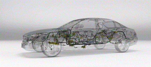
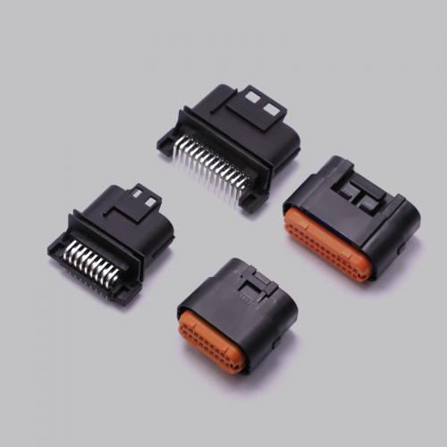
Rugged KR2014 wire-to-board connectors for industrial and automotive applications. High retention design unaffected by vibration or rough handling high retention and internal locking provide electrical reliability in harsh environments.Konnra’s unique, non-rectangular shell shape perfect for dodgy design and reduces manual installation errors.
Disclaimer: Some of the graphics in this article originated from GREENCONN’s official website.