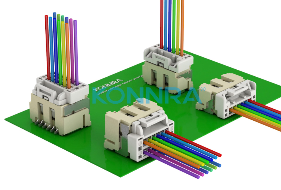
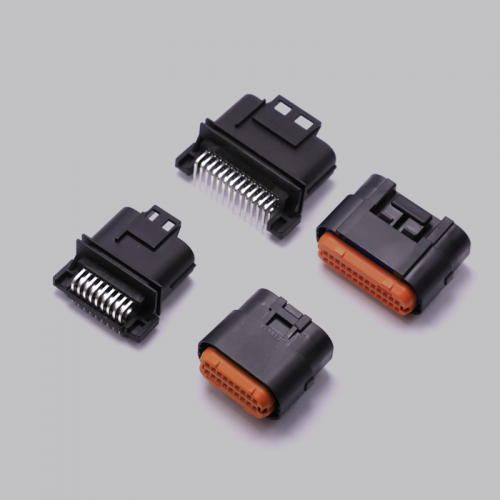
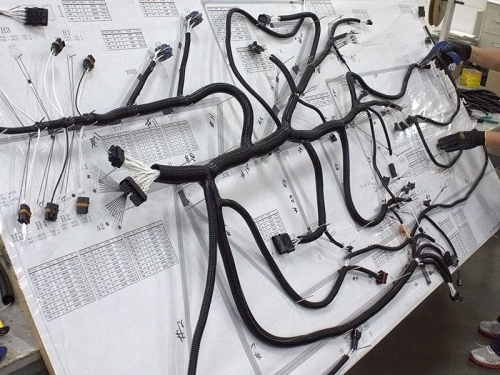
Connectors generally refer to electrical connectors. A device that connects two active devices to transmit a current or signal. The connector is a component that our electronic engineering technicians often come into contact with. Its function is very simple: it creates a connection bridge between the blocked or blocked circuits in the circuit, so that the current can flow and the circuit can achieve the predetermined function. Connectors are an indispensable part of electronic equipment. If you follow the path of the current flow, you can always find one or more connectors.
The form and construction of connectors are constantly changing. According to the application object, frequency, power, application environment, etc., there are various forms of connectors. However, no matter what kind of connector is used, it is necessary to ensure the smooth, continuous and reliable flow of current. The content of the connector connection is not limited to current. With the rapid development of optoelectronic technology today, light is the carrier of signal transmission in optical fiber systems. Glass and plastic replace the wires in ordinary circuits, but the connectors are also used for optical signal paths and function in the same way as circuit connectors.

Applications of connectors:
With the continuous expansion of the application range of connectors, according to its two basic functions, it can be divided into two categories of signal transmission and electrical transmission. The salient feature of these two types of connectors in the field of electronic applications is that their terminals must carry current. In other applications, the voltage provided by the terminals will also be an important consideration. Although the same terminal design can be used as the transmission of signal and power, for many applications with similar contact methods, many electrical transmission connectors design terminals with only the need for power transmission as the sole purpose.
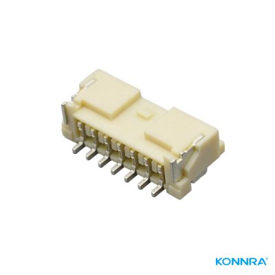
Signal transmission can be divided into two categories: analog signal transmission and digital signal transmission.
Whether it is an analog signal or a digital signal connector, its required function should mainly be able to protect the integrity of the transmitted voltage pulse signal. This integrity should include the waveform of the pulse signal and its amplitude. The data signal and the simulation signal are different in pulse frequency. Its pulse transmission speed determines the maximum frequency of the protected pulse. The data pulse is transmitted much faster than some typical simulated signals. Some pulses are in the connector. Transmission speeds close to the 100 billionth of a second range. In today’s field of microelectronics technology, connectors are often considered wires because the wavelength associated with this rapidly growing frequency can be compared to the size of the connector.
When connectors or interconnect systems such as cable assemblies are used for high-speed data signal transmission, the corresponding description of connector performance changes. Instead of resistance, characteristic impedance and crosstalk in interconnected systems become particularly important. Controlling the characteristic impedance of connectors has become a big trend in consciousness, and in cables it is the control of crosstalk. The reason the characteristic impedance plays such an important role in the connector is that the geometry of the resistor is difficult to be completely uniform, and the size of the connector is small, so the possibility of crosstalk must be minimized. In a cable, it is relatively easy to control the geometry and its characteristic impedance, but the length of the cable can cause potential crosstalk.
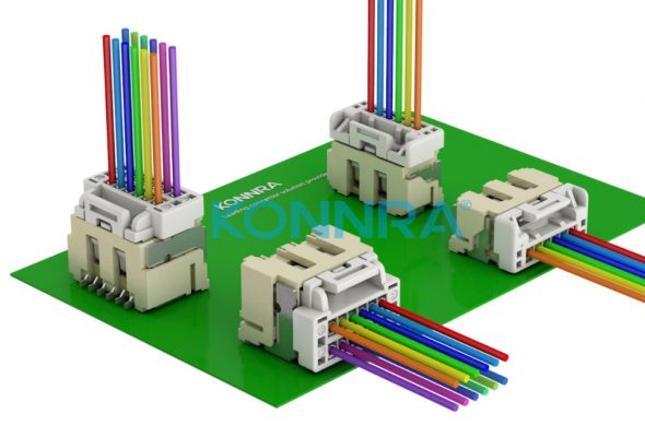
The characteristic impedance in the control connector is developed around this principle. In a typical open terminal area, the impedance (and crosstalk) of the connector is achieved by controlling the terminals to be distributed in a reasonable manner. For such signals, the ground ratio is a reflection of this distribution, and the ground ratio is reduced. This, of course, leads to a reduction in the number of terminals available for transmitting signals. The position of the ground in relation to the signal terminal is an important consideration. To avoid the reduction of ground terminals, connector systems with an integral ground plane have been developed.
Power Application:
As mentioned earlier, the electrical connectors mentioned in this context are necessary to transmit power. Usually it has a very low voltage. The following two power transmission methods are usually used:
(1) Designed for high level current power contact transmission.
(2) Contact with multiple signals in parallel. Each has its advantages and disadvantages.
There are two differences between power transmission and signal transmission. The first, and most obvious, is to pass through higher currents. The current of signal transmission is usually not more than 1 amp, at most a few amps, while the current of power transmission can reach tens or even hundreds of amps. The second point is the increase in temperature due to joule heating caused by the current. The Joule heat generated during signal contact is similar to the ambient temperature. Instead, the ratio of power transmission is based on an increase in temperature, which generates a corresponding proportion of current. A temperature rise of 30 degrees is usually used as the standard current ratio.

Therefore, in order to meet the requirements of rated current and performance stability, the focal ear heat must be controlled, which requires not only signal transmission but also power transmission to be considered in the design. Especially for terminals with high resistance, Joule heat is an important factor and must be reduced to a minimum. In addition, the resistance of the contact surface must also be reduced to a minimum in order to minimize the heat generated. From the point of view of material selection, of course, it is necessary to choose terminals with high conductivity or large cross-sectional area to reduce resistance. In addition, increasing the transmission voltage or increasing the contact area can also reduce the resistance of the contact part.
Higher cross sections and extra contact terminals mean an increase in connector size under contact pressure. That is to say, in practice, there are restrictions on the supply of electrical contacts, including the contact medium and the size of the contacts. The path of the power cable, the end points of the cable’s high-power contacts, and the size of the electrical contacts may be limiting factors in the use of the contributing contacts.
Because of the additional limitations imposed on connector design, parallel multi-signal terminals allow for the use of more traditional connectors to distribute power. These limitations are first and foremost aimed at ensuring that the current distribution through contact is, at the same time, as consistent as possible with their thermal environment. The following three factors are the main ones:
- The circuit should be a parallel flow of electrons; That is, if possible, the voltage drop through all contacts should be the same. If the different voltage drops are fundamental to the use, these circuits will be treated differently.
- If possible, the thermal effects of contact will be minimized, especially if a large beam of current contact is avoided.
- The impedance of the contact or any deviation calculated together in all signal distributions must be the same. For example, depending on the arrangement present at the time of contact, the large impedance of the independent contact of the connectorat the appropriate Angle will vary. These differences should be taken into account when designing distributed contacts.
