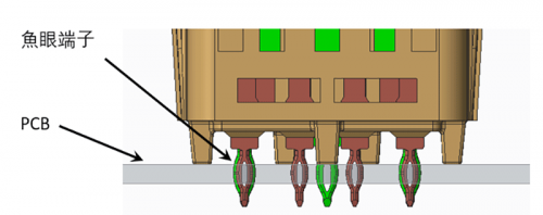
The wire harness terminal is an important electrical component in the wire harness system, and its common fault is pin withdrawal.
- What is terminal pin withdrawal?
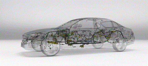
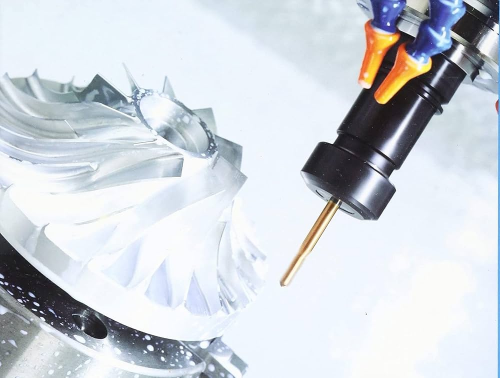
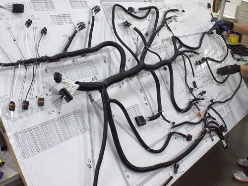
The wiring harness is the neural network system of the car and is responsible for transmitting voltage, signals and large amounts of data during the operation of the vehicle. Especially in the context of the Internet and big data, the wire harness carrier is not only required to play a connecting and disconnecting role, but also puts forward higher requirements for data transmission rate and response capabilities. At the same time, Rework poses greater challenges due to the limited physical layout space of the wire harness.
Terminal pullout is a common failure mode in wiring harnesses. Dropout is when the terminals are not in their expected position, causing the connector to be inactive. Automotive wiring harnesses mainly rely on manual operation, and the difficulty of control can be imagined. In order to better prevent and control terminal withdrawal problems, control is mainly carried out from the following aspects: design selection, process protection, terminal crimping, assembly, electrical testing and assembly.

- Analysis of terminal exit reasons and prevention and control measures
2.1 Design choices
Quality is designed and manufactured, not inspected. Regarding preventing terminal pins from falling off, we first start with design and selection. Here are 5 things to pay attention to.
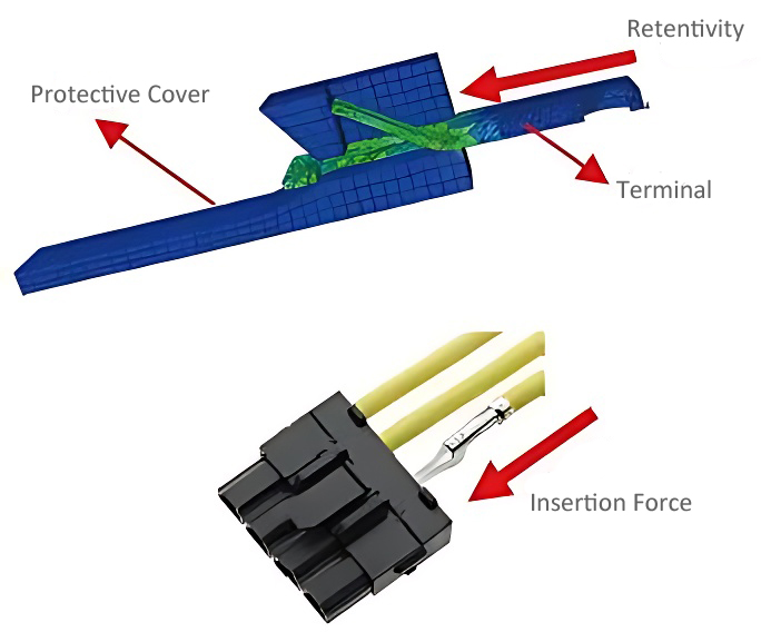
①Insertion force: The difficulty of assembling the terminal immediately. The smaller the resistance of the terminal pre-installed connector, the easier it is to pre-install it in place. Therefore, the primary evaluation index when selecting is insertion force. The lower the insertion force, the easier it is. After assembly, there is less risk of terminal dislodgement.
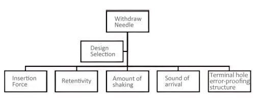
②Retention force: The linear pull-out force of the terminal from the sheath (ie, retention force). The greater the retention force, the harder it is to pop the connectors out when they are inserted into each other. Here, the indicators should be considered when designing and selecting, and the one with greater holding power should be selected. Connectors and terminals.

③Amount of shaking: When male and female connectors are inserted into each other, the amount of shaking of the terminal in the sheath will significantly affect the terminal to be pushed out. In order to reduce the risk of pin withdrawal when male and female connectors are inserted, try to select terminals when designing and selecting. Same manufacturer as the connector (purpose: to ensure minimum amount of wobble when the terminal and connector mate).
④Setting sound: The sound when the terminal is assembled in place. Currently, terminal pre-installation relies on manual labor, and there is a risk of terminal withdrawal. How to allow employees to better recognize that the terminal is pre-installed in place? Here is an assessment indicator, which is the sound of the terminal being pre-installed. The sound of the terminal assembly in place is higher than the ambient sound (the ambient sound level should be 30dB-50dB): 7dB before wetting, 5dB after wetting, or as negotiated by both parties.
⑤ Terminal hole error-proofing structure: When the terminal is inserted in the wrong direction, the terminal cannot be inserted into the terminal hole or the insulating support and seal are exposed outside the terminal hole. While troubleshooting the issue, we discovered that some terminals would be inserted into the connector the wrong way around, making them difficult to identify when pulled back. Therefore, the difficulty of terminal insertion in the wrong direction should be taken into consideration when designing and selecting to ensure that the terminals are inserted in the wrong direction. Terminals will not stay in place when assembled.
2.2 Process protection
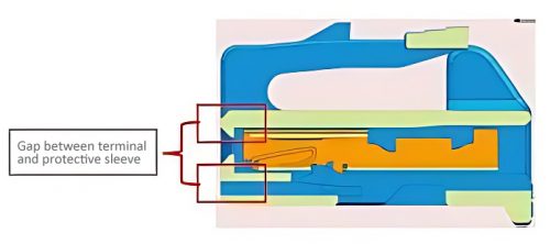
There are two factors that affect the terminal exit: one is the deformation of the shrapnel, and the other is the terminal skew. Both are subject to external forces during processing, causing terminal deformation. In order to protect the terminal shrapnel from deformation due to foreign matter, a protective cup (Figure 7) is required to protect the terminal head after the terminal is crimped, and can be removed during assembly. Lower protective cup. After the wiring harness is assembled, sealing tape or protective tools need to be used to seal the male end sheath (Figure 8) to prevent the terminal from being skewed by foreign objects during transportation.
2.3 Terminal crimping
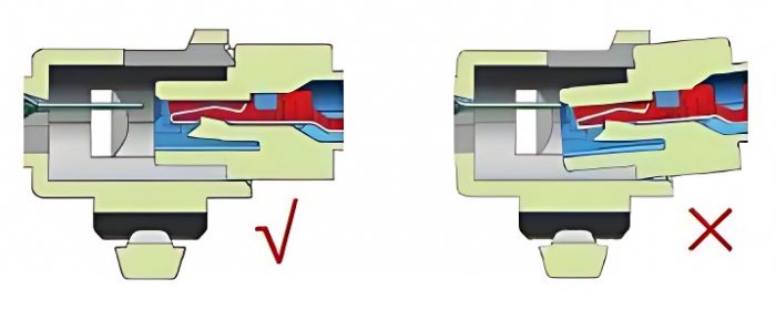
Terminal crimping is a key link in the automotive wiring harness production process. Its main process is to connect the electrical system and terminals, and use machine tool technology to combine the terminals and circuits. Terminal crimping is also a factor that causes terminal shrinkage during the wire harness production process. “Banana” terminals are a common problem during the terminal crimping process. Problems with the crimp die caused excessive bending of the terminals (Figure 9). When the terminal is crimped and assembled, the insertion force of the connector increases, the male terminal cannot be inserted into the effective area of the female terminal, and the terminal pin is retracted. Adjusting the limit pin on the crimping equipment can solve this problem.
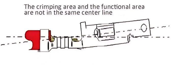
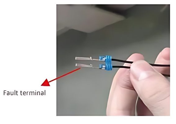
Case: The assembly workshop reported that the terminal pins of a certain model of AC socket were pulled out during the plug-in and pull-out process. The terminal has two states. Comparison revealed that the faulty terminal was banana-shaped. After connecting the device limit pin, this problem is completely solved.
2.4 Assembly
Wire harness assembly mainly relies on manual labor. In order to better reduce the risk of terminal assembly not being in place, the industry generally follows the “one plug, two listen, three pull back” approach, with one plug and play terminals and two plug and play terminals. Insert it into place, and the sound of three pulls indicates that the terminal is inserted and pulled out once to see if the terminal comes out. Employees who plug in terminals thousands of times a day are prone to operator fatigue. In order to better enable employees to form muscle memory, we have made adjustments: First, it means “pull” before a shift and “pull” during breaks. “Pull” here refers to setting the pulling machine in the working position. Before going to work and after breaks, employees need to pull the dynamometer by hand to ensure the formation of insertion force. Muscle memory; the second is “look, insert two, listen three, pull back four”, adding “look” is to identify terminal deformation and banana terminals, and make sure the insertion direction is correct when inserting.
2.5 Electrical measurements
Wire harness electrical measurement is a very important link in wire harness manufacturing. In order to ensure that terminal skew and terminal retraction are effectively identified and intercepted, electrical testing equipment must meet the following conditions: 1. The male terminal fixture must wear an anti-skew grille (as shown in Figure 12) to ensure that skewed terminals cannot be opened; 2. The first is that the electrical measurement probe uses a threaded ladder pin, which can effectively prevent the terminal from being pushed out during the electrical measurement process; the third is to calculate the movement amount of the terminal in the sheath based on the size chain, thereby making the probe and establishing a daily maintenance plan for the probe.
2.6 Assembly
Case: Workshop A reported that it was difficult to install the plug on the left front door control panel of a certain model (the terminal retracted). After on-site investigation and analysis, it was confirmed that the model had been moved from workshop B to workshop A for assembly. The employee did not insert it correctly during assembly, causing damage to the female terminals of the wiring harness. The fault disappeared after popping and aligning the assembly. This case fully illustrates that when assembling a wire harness, employees need to ensure that the male and female end sheaths are correctly inserted (Figure 13) to reduce the risk of the terminals popping out due to misalignment of the male and female end sheaths during the assembly process.
This article briefly discusses the factors that affect the pin withdrawal of automobile wiring harness terminals, conducts an in-depth analysis, and conducts specific prevention and control research from the aspects of design selection, wiring harness manufacturing, process protection, and assembly methods. It not only provides guidance for the design and selection of wire harnesses, but also provides specific opinions on the management and control of the wire harness manufacturing process, and provides specific methods for the analysis of failure modes. To learn more about connector knowledge and applications, please view other articles from Konnra Connectors.